Table of Contents
Advertisement
SPLIT-TYPE AIR CONDITIONERS
INDOOR UNIT
SERVICE MANUAL
Models
MSZ-GC22NA -
MSZ-GC35NA -
NOTE:
RoHS compliant products have <G> mark on the spec name plate.
Revision A:
• MSZ-GC35NA -
Please void OBH481.
C1
C1
C1
C2
C1
C1
C1
CONTENTS
1. PART NAMES AND FUNCTIONS ····················· 3
2. SPECIFICATION ················································ 4
3. OUTLINES AND DIMENSIONS ························ 5
4. WIRING DIAGRAM ············································ 7
5. REFRIGERANT SYSTEM DIAGRAM ··············· 9
6. SERVICE FUNCTIONS ··································· 10
7. MICROPROCESSOR CONTROL ··················· 12
8. TROUBLESHOOTING ····································· 18
9. DISASSEMBLY INSTRUCTIONS ···················· 39
PARTS CATALOG (OBB481)
has been added.
C2
No. OBH481
REVISED EDITION-A
Outdoor unit service manual
MUZ-GC·NA Series(OBH482)
MXZ-A·NA Series (OB430)
Advertisement
Table of Contents
Troubleshooting

Related Manuals for Mitsubishi Electric Mr.Slim MSZ-GC22NA - C1


Summary of Contents for Mitsubishi Electric Mr.Slim MSZ-GC22NA - C1
-
Page 1: Table Of Contents
Revision A: • MSZ-GC35NA - has been added. Please void OBH481. SPLIT-TYPE AIR CONDITIONERS INDOOR UNIT No. OBH481 SERVICE MANUAL REVISED EDITION-A Models MSZ-GC22NA - MSZ-GC25NA - MSZ-GC35NA - MSZ-GC35NA - MSZ-GC50NA - MSZ-GC60NA - MSZ-GC71NA - Outdoor unit service manual MUZ-GC·NA Series(OBH482) MXZ-A·NA Series (OB430) CONTENTS... - Page 2 Revision A: • MSZ-GC35NA - has been added. MSZ-GC35NA → MSZ-GC35NA • FAN MOTOR has been changed. (AC → DC)
-
Page 3: Msz-Gc25Na
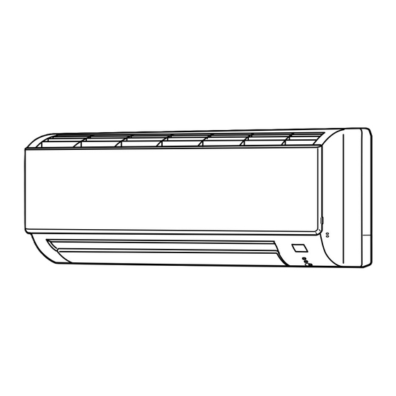
PART NAMES AND FUNCTIONS MSZ-GC22NA MSZ-GC50NA MSZ-GC25NA Air cleaning filter MSZ-GC35NA (Anti-allergy enzyme filter, option) Air inlet Catechin air filter Front panel MSZ-GC60NA MSZ-GC71NA Line flow fan Air outlet Remote controller Vertical vane Horizontal vane MSZ-GC22NA MSZ-GC25NA Remote control MSZ-GC35NA receiving section Emergency operation switch (E.O. -
Page 4: Specification
SPECIFICATION Indoor model MSZ-GC22NA MSZ-GC25NA MSZ-GC35NA Function Cooling Heating Cooling Heating Cooling Heating Power supply Single phase 220 - 230 V, 60 Hz Running current 1 0.24 Electrical data Power input 1 RC4V18-BA Model RC4V18-BA RC0J40-EF Fan motor 0.24 Current 1 0.24 0.27 Dimensions W ×... -
Page 5: Outlines And Dimensions
Specifications and rating conditions of main electric parts Model MSZ-GC22/25/35 MSZ-GC50 MSZ-GC60/71 Item Fuse (F11) T3.15AL 250 V Horizontal vane MSBPC20M16 (MV) 12 VDC — motor 12 VDC 250 Ω (at 25˚C) Vane motor (MV1/MV2) — — MP20/MP20 Varistor (NR11) S10K320E3K1 (ERZV14D471) ERZV14D471 Terminal block (TB) - Page 6 MSZ-GC50NA Unit : mm 11×26 Oblong hole 11×20 Oblong hole Installation plate Air in Wall hole ø Indoor unit Installation plate Liquid line 6.35-0.5 m ø Gas line 9.52-0.43 m ø Insulation 35 O.D ø 19 I.D ø Drain hose ø...
-
Page 7: Wiring Diagram
WIRING DIAGRAM MSZ-GC22NA MSZ-GC25NA MSZ-GC35NA - MSZ-GC35NA -... - Page 8 MSZ-GC50NA MSZ-GC60NA MSZ-GC71NA...
-
Page 9: Refrigerant System Diagram
REFRIGERANT SYSTEM DIAGRAM MSZ-GC22NA MSZ-GC25NA MSZ-GC50NA Unit:mm MSZ-GC35NA Refrigerant pipe ø12.7 Refrigerant pipe ø9.52 (with heat insulator) (with heat insulator) Indoor coil Indoor coil Indoor Indoor thermistor thermistor heat heat RT12(main) RT12(main) exchanger exchanger Flared connection Distributor Flared connection Indoor coil Indoor coil thermistor thermistor... -
Page 10: Service Functions
SERVICE FUNCTIONS MSZ-GC22NA MSZ-GC25NA MSZ-GC35NA MSZ-GC50NA MSZ-GC60NA MSZ-GC71NA 6-1. TIMER SHORT MODE For service, set time can be shortened by short circuit of JPG and JPS on the indoor electronic control P.C. board. The time will be shortened as follows. (Refer to 8-7.) Set time : 1-minute →... - Page 11 6-3. AUTO RESTART FUNCTION When the indoor unit is controlled with the remote controller, the operation mode, the set temperature, and the fan speed are memorized by the indoor electronic control P.C. board. The “AUTO RESTART FUNCTION” sets to work the moment power has restored after power failure.
-
Page 12: Microprocessor Control
MICROPROCESSOR CONTROL MSZ-GC22NA MSZ-GC25NA MSZ-GC35NA MSZ-GC50NA MSZ-GC60NA MSZ-GC71NA WIRELESS REMOTE CONTROLLER These pictures show MSZ-GC60/71 Signal transmitting section Operation display section VANE CONTROL button (Horizontal vane button) FAN SPEED CONTROL button OPERATE /STOP OFF TIMER button OPERATION SELECT button (ON /OFF)button ON/OFF WARM COOL... - Page 13 7-1. COOL ( ) OPERATION (1) Press OPERATE/STOP (ON/OFF) button. OPERATION INDICATOR lamp of the indoor unit turns ON. (2) Select COOL mode with OPERATION SELECT button. (3) Press TEMPERATURE buttons (TOO WARM or TOO COOL button) to select the desired temperature. The setting range is 16 ~ 31°C.
- Page 14 NOTE 2 FOR MULTI SYSTEM AIR CONDITIONER OUTDOOR UNIT : MXZ series Multi system air conditioner can connect two or more indoor units with one outdoor unit. •When you try to operate two or more indoor units with one outdoor unit simultaneously, one for the cool- ing and the others for heating, the operation mode of the indoor unit that operates earlier is selected.
- Page 15 (5) STOP (operation OFF) and ON TIMER standby In the following cases, the horizontal vane returns to the closed position. (a) When OPERATE/STOP (ON/OFF) button is pressed (POWER OFF). (b) When the operation is stopped by the emergency operation. (c) When ON TIMER is ON standby. (6) Dew prevention During COOL or DRY operation with the vane angle at Angle 2 ~ 4 (GC22/25/35/50) / Angle 4 or 5 (GC60/71) when the compressor cumulative operation time exceeds 1 hour, the vane angle automatically changes to Angle 1 for dew preven-...
- Page 16 (11) LONG ( ) MODE (MSZ-GC60/71) By pressing LONG button indoor fan speed becomes faster than setting fan speed on the remote controller, and the horizontal vane moves to the position for LONG mode. The remote controller displays “ ”. LONG mode is cancelled when LONG button is pressed once again or VANE button is pressed or ECONO COOL button is pressed in COOL mode.
- Page 17 7-6. TIMER OPERATION 1. How to set the time (1) Check that the current time is set correctly. NOTE : Timer operation will not work without setting the current time. Initially “0:00” blinks at the current time display of TIME MONITOR, so set the current time correctly with CLOCK SET button. How to set the current time (a) Press the CLOCK set button.
-
Page 18: Troubleshooting
7-7. EMERGENCY/TEST OPERATION In case of test run operation or emergency operation, use EMERGENCY OPERATION switch on the right side of the indoor unit. Emergency operation is available when the remote controller is missing, has failed or the batteries of the remote controller run down. - Page 19 3. Troubleshooting procedure 1) First, check if the OPERATION INDICATOR lamp on the indoor unit is flashing on and off to indicate an abnormality. To make sure, check how many times the abnormality indication is flashing on and off before starting service work. 2) Before servicing, check that the connector and terminal are connected properly.
- Page 20 8-2. FAILURE MODE RECALL FUNCTION Outline of the function This air conditioner can memorize the abnormal condition which has occurred once. Even though LED indication listed on the troubleshooting check table (8-4.) disappears, the memorized failure details can be recalled. This mode is very useful when the unit needs to be repaired for the abnormality which doesn't recur.
- Page 21 2. Indoor unit failure mode table Upper or left lamp Abnormal point of OPERATION Condition Correspondence (Failure mode) INDICATOR lamp Not lighted Normal — — The room temperature thermistor short or 1-time fl ash every Room temperature Refer to the characteristics of the room temperature open circuit is detected every 8 seconds dur- 0.5-second thermistor...
- Page 22 8-3. INSTRUCTION OF TROUBLESHOOTING Start Indoor unit operates. Indoor unit oper- Indoor unit OPERATION INDICATOR Outdoor unit doesn't doesn't receive ates. lamp on the indoor unit is operate normally. the signal from Outdoor unit fl ashing on and off. doesn't operate. remote controller.
- Page 23 8-4. TROUBLESHOOTING CHECK TABLE Before taking measures, make sure that the symptom reappears for accurate troubleshooting. When the indoor unit has started operation and the following detection method has detected an abnormality (the first detection after the power ON), the indoor electronic control P.C. board turns OFF the indoor fan motor with OPERATION INDICATOR lamp flashing.
- Page 24 Abnormal Operation indicator lamp Symptom Condition Correspondence point All lamps fl ash at the same time. GC22/25/35 Indoor unit and 0.5-second ON Attachment The electricity is not conducted to the inter- • Refer to 8-6. "Check of instal- outdoor unit do of the hori- lock switch (Fan) of the horizontal vane.
-
Page 25: Troubleshooting Flow
8-6. TROUBLESHOOTING FLOW A Check of indoor fan motor The indoor fan motor error has occurred, and the indoor fan doesn't operate. MSZ-GC22/25/NA MSZ-GC35/NA - Turn OFF the power supply. Check connector CN211 visually. Are soldered points of the connector Reconnect the lead wires. - Page 26 MSZ-GC35/NA - Turn OFF the power supply. Pay careful attention to the high voltage on the fan motor connector CN211. Turn ON the power supply, wait 5 seconds or more, and press EMER- GENCY OPERATION switch. Measure the supply voltage as follows within 12 seconds after EMER- GENCY OPERATION switch is pressed.
- Page 27 MSZ-GC50/60/71NA Turn OFF the power supply. Pay careful attention to the high voltage on the fan motor connector CN211. Turn ON the power supply, wait 5 seconds or more, then press EMER- GENCY OPERATION switch. Measure the supply voltage as follows within 12 seconds after EMER- Is there any foreign matter that interferes GENCY OPERATION switch is pressed.
- Page 28 B Check of remote controller and indoor P.C. board Check if the remote controller is exclusive for this air conditioner. Press OPERATE/STOP (ON/OFF) button on the remote controller. Is LCD display on the remote con- Replace the batteries. (Refer to 8-1.4.) troller visible? (Not clear) Remove the batteries, then set them back...
- Page 29 C Check of indoor P.C. board and indoor fan motor MSZ-GC22/25/35NA Turn OFF the power supply. Remove indoor fan motor connector CN211 from indoor power P.C. board and vane Measure the resistance of indoor fan Short circuit : motor connector CN151 from the indoor motor.
- Page 30 MSZ-GC50/60/71NA Turn OFF the power supply. Remove indoor fan motor connector CN211 Measure the resistance between Short/open circuit: CN211 of the indoor fan motor and vane motor connector CN151 from the Replace the indoor fan motor. connector. indoor electronic control P.C. board and turn ON the power supply.
- Page 31 D How to check miswiring and serial signal error MSZ-GC22/25/35NA Turn OFF the power supply. Is there rated voltage in the Check the power supply. power supply? Turn ON the power supply. Is there rated voltage between outdoor terminal block S1 and Check the wiring.
- Page 32 MSZ-GC50/60/71NA Turn OFF the power supply. Is there rated voltage in the Check the power supply. power supply? Turn ON the power supply. Is there rated voltage between outdoor termi- Check the wiring. nal block S1 and S2? Press EMERGENCY OPERATION switch once. Does the left lamp of OPERATION INDICA- TOR lamp light up? <Confi...
- Page 33 E Check of installation of the horizontal vane MSZ-GC22/25/35/50NA Turn OFF the power supply. Relock the stopper of the horizon- Is the stopper of the horizontal vane Turn ON the tal vane to the indoor unit. locked to the indoor unit correctly? power supply.
- Page 34 F Electromagnetic noise enters into TV sets or radios Is the unit earthed? Earth the unit. Is the distance between the antennas Extend the distance between the antennas and and the indoor unit within 3 m, or is the the indoor unit, and/or the antennas and the distance between the antennas and the outdoor unit.
- Page 35 8-7. Test point diagram and voltage 1. Indoor power P.C. board, Indoor terminal P.C. board MSZ-GC22NA MSZ-GC25NA MSZ-GC35NA - Indoor terminal P.C. board Indoor power P.C. board Varistor (NR11) Cement resistor (R111) Fuse (F11)( ) Indoor fan motor (CN211) Terminal 220-230V AC block Connector to indoor electronic...
- Page 36 2. Indoor electronic control P.C. board MSZ-GC22NA MSZ-GC25NA MSZ-GC35NA Timer short mode point JPG JPS (Refer to 6-1.) Room temperature thermistor RT11 (CN111) Indoor coil thermistor RT12, RT13 (CN112) Interlock switch(FAN)(CN1R1) Room temperature thermistor (RT11) Vane motor (CN151) Indoor coil thermistor (RT12, RT13) Connector to Indoor power P.C.
- Page 37 MSZ-GC50NA Power supply input Varistor (NR11) 220-230 VAC Fuse(F11) Cement resistor (R111) Indoor fan motor (CN211) 311-325 VDC (-) Fiducial terminal of cathode side on measur- ing high-voltage DC 15 VDC (+)3-6 VDC Release of Auto restart (+)0 or 15 VDC function Solder the Jumper wire Interlock switch(Fan)
- Page 38 MSZ-GC60NA MSZ-GC71NA Release of Auto restart Power supply input function Varistor (NR11) 220-230V AC Fuse(F11) Solder the Jumper wire to JR07 (Refer to 6-3.) Cement resistor (R111) Indoor fan motor (CN211) 311-325 VDC (-) Fiducial terminal of cathode side on meas- uring high-voltage DC Display 15 VDC...
-
Page 39: Disassembly Instructions
DISASSEMBLY INSTRUCTIONS <"Terminal with locking mechanism" Detaching points> The terminal which has the locking mechanism can be detached as shown below. There are two types (refer to (1) and (2)) of the terminal with locking mechanism. The terminal without locking mechanism can be detached by pulling it out. Check the shape of the terminal before detaching. - Page 40 OPERATING PROCEDURE PHOTOS 3. Remove the indoor power P.C. board, the indoor ter- Photo 3 minal P.C. board, and the electrical box Catch of indoor electronic (1) Turn the breaker OFF. control P.C. board holder Terminal block (2) Remove the panel (Refer to 1) and the corner box. (3) Remove the screw of V.A.
- Page 41 OPERATING PROCEDURE PHOTOS 5. Removing the indoor fan motor, the indoor coil ther- Photo 5 mistor, and the line flow fan (1) Remove the panel (refer to 1.) and the corner box. (2) Remove the indoor electronic control P.C. board holder (refer to 2.) and the electrical box (refer to 3.) .
- Page 42 9-2. MSZ-GC50NA OPERATING PROCEDURE PHOTOS 1. Removing the panel Photo 1 (1) Remove the horizontal vane. (2) Remove the screw caps of the panel. Remove the screws. (Photo 1) (3) Hold the lower part of both ends on the panel and pull it slightly toward you, and then remove the panel by pushing it upward.
-
Page 43: Terminal Block
OPERATING PROCEDURE PHOTOS 2. Removing the electronic control P.C. board, the power Photo 2 monitor receiver P.C. board, SW P.C. board and the terminal block (1) Remove the horizontal vane, the panel (refer to 1.) and the corner box. (2) Remove the screw of V.A. clamp, and the indoor/outdoor connecting wire. - Page 44 OPERATING PROCEDURE PHOTOS 4. Removing the horizontal vane motor unit Photo 5 (1) Remove the horizontal vane and the panel. (Refer to 1.) (2) Remove the screws of the horizontal vane motor unit, and pull out the horizontal vane motor unit. (Photo 5) Screws of the (3) Disconnect the connector from the horizontal vane motor horizontal vane...
- Page 45 9-3.MSZ-GC60NA MSZ-GC71NA OPERATING PROCEDURE PHOTOS 1. Removing the front panel Photo 1 (1) Remove the screw caps of the front panel. Remove the screws. Front panel (2) Pull the panel down to your side slightly and unhook the catches at the top. Screws 2.
- Page 46 OPERATING PROCEDURE PHOTOS Photo 4 4. Removing the vane motor (1) Remove the front panel. (Refer to 1.) (2) Remove the electrical cover. (Refer to 2.) Vane motors Screws (3) Remove the lead wire of vane motor. (Refer to 3.) of the (4) Remove the R.L.
- Page 48 HEAD OFFICE: TOKYO BLDG., 2-7-3, MARUNOUCHI, CHIYODA-KU, TOKYO 100-8310, JAPAN Copyright 2007 MITSUBISHI ELECTRIC ENGINEERING CO.,LTD Distributed in Aug. 2008. No. OBH481 REVISED EDITION-A 6 New publication, effective Aug. 2008 Distributed in Mar. 2007. No. OBH481 Specifications subject to change without notice.
Need help?
Do you have a question about the Mr.Slim MSZ-GC22NA - C1 and is the answer not in the manual?
Questions and answers
Comment me procurer une nouvelle télécommande Type KM16G0003401