
Subscribe to Our Youtube Channel
Related Manuals for Panasonic MDF-C8V1 Series


Summary of Contents for Panasonic MDF-C8V1 Series
-
Page 1: Operating Instructions
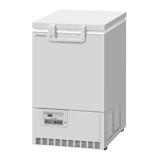
Operating Instructions Ultra-Low Temperature Freezer MDF-C8V1 MDF-C8V1 Series Please read these instructions carefully before using this product, and save this operating instructions for future use. See page 38 for all Model Numbers. -
Page 2: Table Of Contents
CONTENTS INTRODUCTION P. 2 PRECAUTIONS FOR SAFE OPERATION P. 3 ENVIRONMENTAL CONDITIONS P. 7 FREEZER COMPONENTS P. 8 Control panel P. 10 INSTALLATION SITE P. 11 INSTALLATION P. 12 START-UP OF UNIT P. 13 CHAMBER TEMPERATURE SETTING P. 14 KEY LOCK FUNCTION P. -
Page 3: Introduction
INTRODUCTION Read this operating instructions carefully before using the appliance and follow the instructions for safety operation. Our company never guarantee any safety if the appliance is used for any objects other than intended use or used by any procedures other than those mentioned in this operating instructions. Keep this operating instructions in an adequate place to refer to it as necessary. -
Page 4: Precautions For Safe Operation
PRECAUTIONS FOR SAFE OPERATION It is imperative that the user complies with this operating instructions as it contains important safety advice. Items and procedures are described so that you can use this unit correctly and safely. If the precautions advised are followed, this will prevent possible injury to the user and any other person. - Page 5 PRECAUTIONS FOR SAFE OPERATION WARNING Do not use the unit outdoors. Current leakage or electric shock may result if the unit is exposed to rain water. Only qualified engineers or service personnel should install the unit. The installation by unqualified personnel may cause electric shock or fire. Install the unit on a sturdy floor and take an adequate precaution to prevent the unit from turning over.
- Page 6 PRECAUTIONS FOR SAFE OPERATION WARNING Ensure you do not inhale or consume medication or aerosols from around the unit at the time of maintenance. These may be harmful to your health. Never splash water directly onto the unit as this may cause electric shock or short circuit. Never put containers with liquid on the unit as this may cause electric shock or short circuit when the liquid is spilled.
- Page 7 PRECAUTIONS FOR SAFE OPERATION CAUTION Use a dedicated power source (a dedicated circuit with a breaker) as indicated on the rating label attached to the unit. A branched circuit may cause fire resulting from abnormal heating. Connect the power supply plug to the power source firmly after removing the dust on the plug. A dusty plug or improper insertion may cause a heat or ignition.
-
Page 8: Environmental Conditions
ENVIRONMENTAL CONDITIONS This equipment is designed to be safe at least under the following conditions (based on the IEC61010-1): Indoor use; Altitude up to 2000 m; Ambient temperature 5 C to 40 Maximum relative humidity 80% for temperature up to 31 C decreasing linearly to 50% relative humidity at 40 Mains supply voltage fluctuations up to ±10% of the nominal voltage;... -
Page 9: Freezer Components
FREEZER COMPONENTS... - Page 10 FREEZER COMPONENTS 1. Lock: By turning to 180 degree to clockwise with a key, the door can be locked. 2. Door: Top hinged type. To open the door, grip the handle. 3. Door gasket: Seals the door and prevents leakage of cold air. 4.
-
Page 11: Control Panel
FREEZER COMPONENTS Control panel 1. Digital temperature indicator (TEMPERATURE): This indicator shows the present chamber temperature or set temperature. 2. Battery check lamp (BATTERY): This lamp lights to recommend the battery replacement. For the replacement, consult our sales representative or agent. 3. -
Page 12: Installation Site
INSTALLATION SITE To operate this unit properly and to obtain maximum performance, install the unit in a location with the following conditions: A location not subjected to direct sunlight Do not install the unit under direct sunlight. Installation in a location subjected to direct sunlight cannot obtain the intended performance. -
Page 13: Installation
INSTALLATION 1. Removing the packaging materials and tapes Remove all transportation packaging materials and tapes. Open the doors and ventilate the unit. If the outside panels are dirty, clean them with a diluted neutral dishwashing detergent. (Undiluted detergent can damage the plastic components. For the dilution, refer to the instruction of the detergent.) After the cleaning with the diluted detergent, always wipe it off with a wet cloth. -
Page 14: Start-Up Of Unit
START-UP OF UNIT Follow the procedures for the initial and consequent operations of the unit. 1. Check that the power switch and battery switch are OFF. 2. Connect the power cord to the dedicated outlet having appropriate rating with the chamber empty. 3. -
Page 15: Chamber Temperature Setting
CHAMBER TEMPERATURE SETTING Table 1 shows the basic procedure for setting the chamber temperature. Perform key operations in the sequence indicated in the table. The example in the table is based on the assumption that the desired temperature is -75 Note: The chamber temperature is set to -80 C at the factory. -
Page 16: Function Mode
FUNCTION MODE This unit has the following function mode. Indication Mode Settable range Between 5 and 20 C higher than the Setting of high temperature alarm chamber set temperature (1 C gradient) Between -5 and -20 C lower than the Setting of low temperature alarm chamber set temperature (1 C gradient) - Page 17 ALARM TEMPERATURE SETTING Table 4 Procedure for setting low temperature alarm Description of operation Key operated Indication after operation ---- The current chamber temperature is displayed. Press numerical value shift key for The right digit is flashed. 5 seconds. Press numerical value shift key and When pressed, the figure of settable scroll the figure to 2.
-
Page 18: Setting Of Alarm Resume Time
SETTING OF ALARM RESUME TIME The alarm buzzer is silenced by pressing alarm buzzer stop key (BUZZER) key on the control panel during alarm condition (The remote alarm cannot stopped. ). The buzzer will be activated again after certain suspension if the alarm condition is continued. The suspension time can be set by following the procedure shown in the Table 5 below. -
Page 19: Change Of Compressor Delay Time
CHANGE OF COMPRESSOR DELAY TIME The delay time of the compressor can be changed to reduce the load on the power line and to facilitate the start-up (reset) of the freezer after power failure. The example in the table is based on the assumption that the delay time is changed to 4 minutes. The delay time is set in 3 minutes at the factory. -
Page 20: Remote Alarm Terminal
REMOTE ALARM TERMINAL WARNING Always disconnect the power supply cord before connecting an alarm device to the remote alarm terminal. The terminal of the remote alarm is installed at the back of the unit. The alarm is generated from this terminal. -
Page 21: Alarms & Safety Functions
ALARMS & SAFETY FUNCTIONS This unit has the alarms and safety functions shown in Table 7, and also self diagnostic functions. Table 7 Alarms and safety functions Alarm & Safety Situation Indication Buzzer Safety operation If the chamber temperature is higher Alarm lamp is flashed. -
Page 22: Routine Maintenance
ROUTINE MAINTENANCE WARNING Always disconnect the power supply to the unit prior to any repair or maintenance of the unit in order to prevent electric shock or injury. Ensure you do not inhale or consume medication or aerosols from around the unit at the time of maintenance. -
Page 23: Battery
ROUTINE MAINTENANCE Battery The battery for power failure alarm is an article for consumption. The battery life is approximately 3 years. The buzzer and alarm lamp cannot be activated at the power failure and the stored items may be influenced if the battery is left as it is for more than 3 years. It is recommended that the battery is replaced ahead of time. -
Page 24: Replacement Of Battery
REPLACEMENT OF BATTERY Location of a nickel-metal-hydride battery This unit is provided a nickel-metal-hydride battery for the power failure warning device. The battery is located at the back of the control panel. (Fig. 1) The high voltage components are enclosed in the side cover. The side cover should be removed by a qualified engineer or a service personnel only to prevent the electric shock. -
Page 25: Troubleshooting
TROUBLESHOOTING If the unit malfunctions, check out the following before calling for service. Malfunction Check/Remedy The freezer does not run The power cord is not connected to the proper outlet. The power source does not have enough capacity. The power failure is occurred. The circuit breaker of power source is active. -
Page 26: Disposal Of Unit
DISPOSAL OF UNIT WARNING If the unit is to be stored unused in an unsupervised area for an extended period ensure that children do not have access and doors cannot be closed completely. The disposal of the unit should be accomplished by appropriate personnel. Always remove doors to prevent accidents such as suffocation. - Page 27 The symbol mark and recycling systems described below apply to EU countries and do not apply to countries in other areas of the world. Your Panasonic product is designed and manufactured with high quality materials and components which can be recycled and/or reused.
- Page 28 POUR LES UTILISATEURS DE UE Le symbole et les systèmes de recyclage évoqués ci-dessous s'appliquent uniquement aux pays de UE. Votre produit Panasonic est conçu et fabriqué avec des composants et des matériaux de hautes qualités qui peuvent être recyclés et/ou réutilisés.
- Page 29 O símbolo e os sistemas de reciclagem descritos abaixo aplicam-se aos países da UE e não se aplicam aos países noutras áreas do mundo. O seu produto Panasonic foi concebido e fabricado com materiais e componentes de elevada qualidade que podem ser reciclados e/ou reutilizados.
- Page 30 Het symbool en de recycleersystemen die hieronder beschreven worden, zijn van toepassing op de landen in de EU en zijn niet van toepassing op landen in andere delen van de wereld. Uw Panasonic product is ontworpen en gemaakt met materialen en onderdelen van hoge kwaliteit, die gerecycleerd en opnieuw gebruikt kunnen worden.
-
Page 31: Temperature Recorder (Option)
TEMPERATURE RECORDER (OPTION) WARNING Always disconnect the power supply to the unit prior to attachment of a temperature recorder in order to prevent electric shock or injury. A temperature recorder is available for the freezer as the optional component. The type of the temperature recorder is MTR-85H, MTR-G85A/MTR-G85C. -
Page 32: Installation Of Mtr-85H
TEMPERATURE RECORDER (OPTION) Installation of MTR-85H 1. Remove 4 screws (A, B, C, D) on the side of the front panel to take off the front panel. Then remove 4 Front panel screws on the cover for the recorder mounting space and take off the cover (Fig. - Page 33 TEMPERATURE RECORDER (OPTION) 5. Seal the access port on the outside with putty as shown in Fig. 4. Putty 7. Replace the front panel and fix it with 4 screws. 8. Operate the freezer until the chamber temperature gets to the set temperature. Check the recorded temperature and chamber temperature displayed on the control panel.
-
Page 34: Installation Of Mtr-G85A/Mtr-G85C
TEMPERATURE RECORDER (OPTION) Installation of MTR-G85A/MTR-G85C 1. Remove 4 screws (A, B, C, D) on the side of the front panel to take off the front panel. Then remove 4 Front panel screws on the cover for the recorder mounting space and take off the cover (Fig. - Page 35 TEMPERATURE RECORDER (OPTION) 5. Fix the recorder sensor to the inside of the sensor cover (MTR-C8) by using the enclosed clips and screws and seal the access port on the chamber side with a silicon. (Fig. 3) Silicon Recorder sensor 6.
-
Page 36: Backup Cooling Kit (Option)
BACKUP COOLING KIT (OPTION) This freezer can be provided with a Backup cooling kit (CVK-UB4) which is available as an optional component. For the installation, refer to the instruction manual enclosed with the backup cooling kit. BACK UP STANDBY BATTERY CVK-UB4 control panel CVK-UB4 switch box 1. - Page 37 BACKUP COOLING KIT (OPTION) With the Backup cooling kit (CVK-UB4), the freezer prevents the chamber temperature from going up by injecting the liquid CO gas when the power supply is disconnected (power failure, disconnection of power cord, breaker OFF) or in the case of failure of freezer itself. The liquid CO gas is injected with the activation of solenoid valve energized by battery when the chamber temperature reaches the alarm temperature.
-
Page 38: Specifications
SPECIFICATIONS Ultra-Low Temperature Freezer Product name MDF-C8V1 External dimensions W550 mm x D685 (+83)* mm x H945 mm Internal dimensions W405 mm x D490 mm x H425 mm Effective capacity 84 L Exterior Painted steel Interior Painted steel Door Painted steel Access port Diameter 17 mm, back side, bottom Cabinet;... -
Page 39: Performance
PERFORMANCE Ultra-Low Temperature Freezer Product name MDF-C8V1 Model No. MDF-C8V1-PT MDF-C8V1-PA MDF-C8V1-PE MDF-C8V1-PK Cooling performance C (ambient temperature; 30 C, no load) Temperature control range C to -80 C (ambient temperature; 30 C, no load) Rated voltage AC 220 V/ 230V/ AC 110 V AC 115 V AC 220V... -
Page 40: Safety Check Sheet
CAUTION Please fill in this form before servicing. Hand over this form to the service engineer to keep for his and your safety. Safety check sheet 1. Freezer contents : □Yes □No Risk of infection: □Yes □No Risk of toxicity: □Yes □No Risk from radioactive sources:... - Page 41 1-1-1, Sakata Oizumi-Machi Ora-Gun, Gunma 370-0596, Japan Printed in Japan 7FB6P151513001 © Panasonic Healthcare Co., Ltd. 2012 S0412-10512...
Need help?
Do you have a question about the MDF-C8V1 Series and is the answer not in the manual?
Questions and answers