Please read these instructions carefully before using this product, and save this operating instructions
for future use.
See page 42 for all Model Numbers.
Operating Instructions
Ultra-Low Temperature Freezer
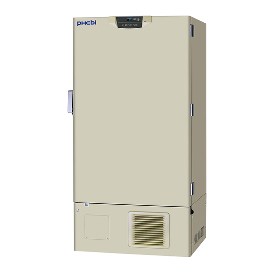
MDF-U55V
MDF-U74V
MDF-U55V
MDF-U74V
MDF-U55V


Need help?
Do you have a question about the MDF-U74V and is the answer not in the manual?
Questions and answers