Table of Contents

Related Manuals for Panasonic MDF-U4186S Series


Summary of Contents for Panasonic MDF-U4186S Series
-
Page 1: Operating Instructions
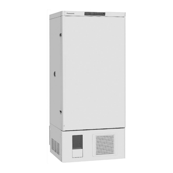
Operating Instructions Ultra-Low Temperature Freezer MDF-U4186S MDF-U4186S Series Please read these instructions carefully before using this product, and save this operating instructions for future use. See page 33 for all Model numbers. -
Page 2: Table Of Contents
CONTENTS INTRODUCTION P. 2 PRECAUTIONS FOR SAFE OPERATION P. 3 ENVIRONMENTAL CONDITIONS P. 7 FREEZER COMPONENTS P. 8 Control panel P. 10 INSTALLATION SITE P. 11 INSTALLATION P. 12 ATTENTION P. 13 START-UP OF UNIT P. 14 CHAMBER TEMPERATURE SETTING P. -
Page 3: Introduction
INTRODUCTION Read this operating instructions carefully before using the appliance and follow the instructions for safety operation. Our company never guarantee any safety if the appliance is used for any objects other than intended use or used by any procedures other than those mentioned in this operating instructions. Keep this operating instructions in an adequate place to refer to it as necessary. -
Page 4: Precautions For Safe Operation
PRECAUTIONS FOR SAFE OPERATION It is imperative that the user complies with this operating instructions as it contains important safety advice. Items and procedures are described so that you can use this unit correctly and safely. If the precautions advised are followed, this will prevent possible injury to the user and any other person. - Page 5 PRECAUTIONS FOR SAFE OPERATION WARNING Do not use the unit outdoors. Current leakage or electric shock may result if the unit is exposed to rain water. Only qualified engineers or service personnel should install the unit. The installation by unqualified personnel may cause electric shock or fire. Install the unit on a sturdy floor and take an adequate precaution to prevent the unit from turning over.
- Page 6 PRECAUTIONS FOR SAFE OPERATION WARNING Ensure you do not inhale or consume medication or aerosols from around the unit at the time of maintenance. These may be harmful to your health. Never splash water directly onto the unit as this may cause electric shock or short circuit. Never put containers with liquid on the unit as this may cause electric shock or short circuit when the liquid is spilled.
- Page 7 PRECAUTIONS FOR SAFE OPERATION CAUTION Use a dedicated power source (a dedicated circuit with a breaker) as indicated on the rating label attached to the unit. A branched circuit may cause fire resulting from abnormal heating. Connect the power supply plug to the power source firmly after removing the dust on the plug. A dusty plug or improper insertion may cause a heat or ignition.
-
Page 8: Environmental Conditions
ENVIRONMENTAL CONDITIONS This equipment is designed to be safe at least under the following conditions (based on the IEC61010-1): Indoor use; Altitude up to 2000 m; Ambient temperature 5 C to 40 Maximum relative humidity 80% for temperature up to 31 C decreasing linearly to 50% relative humidity at 40 Mains supply voltage fluctuations up to ±10% of the nominal voltage;... -
Page 9: Freezer Components
FREEZER COMPONENTS... - Page 10 FREEZER COMPONENTS 1. Outer door: To open the door, grip the handle. On closing, make sure to lock the latch completely. 2. Magnetic door gasket: Provides a tight door seal and prevents cold air leak. 3. Inner door: Composed of separated door flaps for minimizing temperature rise when putting in and taking out refrigerated articles.
-
Page 11: Control Panel
FREEZER COMPONENTS Control panel ALARM FILTER CHECK TEMPERATURE( BUZZER ALARM PV/SV BACK UP 1. Alarm buzzer stop key (BUZZER): To stop the alarm from sounding, press this key. Should a further abnormality occur, the buzzer will sound automatically. 2. Alarm test key (ALARM): Check that the alarm lamp and the buzzer functional when the freezer is operating well. -
Page 12: Installation Site
INSTALLATION SITE To operate this unit properly and to obtain maximum performance, install the unit in a location with the following conditions: A location not subjected to direct sunlight Do not install the unit under direct sunlight. Installation in a location subjected to direct sunlight cannot obtain the intended performance. -
Page 13: Installation
INSTALLATION 1. Removing the packaging materials and tapes Remove all transportation packaging materials and tapes. Open the doors and ventilate the unit. If the outside panels are dirty, clean them with a diluted neutral dishwashing detergent. (Undiluted detergent can damage the plastic components. For the dilution, refer to the instruction of the detergent.) After the cleaning with the diluted detergent, always wipe it off with a wet cloth. -
Page 14: Attention
ATTENTION The unit with CE mark is equipped with a circuit breaker on the front. Make sure this breaker is switched ON before the unit is started to run. When the operation of the unit is stopped by this breaker, contact a dealer or a service station after disconnecting the power supply plug. -
Page 15: Start-Up Of Unit
START-UP OF UNIT Follow the procedures for the initial and consequent operations of the unit. 1. Connect the power cord to the dedicated outlet having appropriate rating with the chamber empty, and turn on the power switch on the freezer. 2. -
Page 16: Chamber Temperature Setting
CHAMBER TEMPERATURE SETTING Table 1 shows the basic operation method. Perform key operations in the sequence indicated in the table. The example in the table is the explanation based on the assumption that the temperature is –75 *The unit is set at the factory that the chamber temperature is -80 Table 1. -
Page 17: Alarm Temperature Setting
ALARM TEMPERATURE SETTING This unit is provided with the high temperature alarm. The setting of high temperature alarm is 10 C or C (The setting value is 2 kinds.) higher than the setting of chamber temperature. The procedure in table 2 shows the sequence to set the high temperature alarm at 15 C higher than the setting of chamber temperature. -
Page 18: Setting Of Alarm Resume Time
SETTING OF ALARM RESUME TIME The alarm buzzer is silenced by pressing alarm buzzer stop key (BUZZER) on the control panel during alarm. The buzzer will be activated again after certain suspension if the alarm condition is continued. The suspension time can be set by following the procedure shown in the table 3 below. The example in the table is based on the assumption that the desired duration is 20 minutes. -
Page 19: Remote Alarm Terminal
REMOTE ALARM TERMINAL The terminal of the remote alarm is installed at the upper side of the unit. The alarm is outputted from this terminal. Contact capacity is 2 A (DC 30 V) - 0.1 mA (DC 1 V). a) output: normal open connectors are connected with N.O. - Page 20 ALARMS & SAFETY FUNCTIONS Table 4. Alarm and safety function Alarm & safety Situation Indication Buzzer Safety operation Alarm lamp blinks. If the thermal sensor is E01 and 50 C is disconnected. Remote alarm displayed alternately. Intermittent Continuous Alarm lamp blinks. tone operation If the thermal sensor is...
-
Page 21: Routine Maintenance
ROUTINE MAINTENANCE WARNING Always disconnect the power supply to the unit prior to any repair or maintenance of the unit in order to prevent electric shock or injury. Ensure you do not inhale or consume medication or aerosols from around the unit at the time of maintenance. -
Page 22: Cleaning Of Condenser Filter
ROUTINE MAINTENANCE Cleaning of condenser filter This unit is provided with the filter check lamp. This lamp blinks when the condenser filter is clogged. Clean the filter according to the following procedure. As a clogged filter may cause poor cooling and compressor trouble, clean it once a month. -
Page 23: Troubleshooting
TROUBLESHOOTING If the unit malfunctions, check out the following before calling for service. Malfunction Check/Remedy The voltage is too low (In this case, call an electrician). The chamber is not cooled The power is not supplied. at all The breaker is free. The ambient temperature is too high. -
Page 24: Disposal Of Unit
DISPOSAL OF UNIT WARNING If the unit is to be stored unused in an unsupervised area for an extended period ensure that children do not have access and doors cannot be closed completely. The disposal of the unit should be accomplished by appropriate personnel. Always remove doors to prevent accidents such as suffocation. - Page 25 Waste Electrical and Electronic Equipment (WEEE) Directive-2002/96/EC (English) Your Panasonic product is designed and manufactured with high quality materials and components which can be recycled and reused. This symbol means that electrical and electronic equipment, at their end-of-life, should be disposed of separately from your household waste.
- Page 26 DISPOSAL OF UNIT (French) Votre produit Panasonic est conçu et fabriqué avec des matèriels et des composants de qualité supérieure qui peuvent être recyclés et réutilisés. Ce symbole signifie que les équipements électriques et électroniques en fin de vie doivent être éliminés séparément des ordures ménagères.
- Page 27 DISPOSAL OF UNIT (Portuguese) O seu produto Panasonic foi concebido e produzido com materiais e componentes de alta qualidade que podem ser reciclados e reutilizados. Este símbolo significa que o equipamento eléctrico e electrónico no final da sua vida útil deverá ser descartado separadamente do seu lixo doméstico.
- Page 28 Alstublieft help allen mee om het milieu te beschermen. (Swedish) Din Panasonic produkt är designad och tillverkad av material och komponenter med hög kvalitet som kan återvinnas och återanvändas. Denna symbol betyder att elektriska och elektroniska produkter, efter slutanvändande, skall sorteras och lämnas separat från Ditt hushållsavfall.
-
Page 29: Disposal Of Battery
DISPOSAL OF BATTERY Location of a nickel-metal-hydride battery This unit is provided with a nickel-metal hydride battery for the power failure and high temperature warning device. The battery is located near the temperature control device behind the control panel. (Fig. 1) The high voltage components are enclosed in the control box. -
Page 30: Temperature Recorder (Option)
TEMPERATURE RECORDER (OPTION) If the warning is required for the internal temperature record or the interior temperature deviates from the target temperature, an optional temperature recorder (MTR-85H) is available. Install the temperature recorder properly as described below. Temperature Warning indicator Warning indicator Recording indicator Time... - Page 31 TEMPERATURE RECORDER (OPTION) Setting of backup temperature 1. There is a red guide on the top of the temperature displayer. Adjust the guide with your finger to back-up temperature, at which temperature the auxiliary cooling system starts to operate. 2. Set at a temperature 15 C higher than that of the freezer compartment.
-
Page 32: Backup Cooling Kit (Option)
BACKUP COOLING KIT (OPTION) WARNING As with any equipment that uses CO gas, there is a likelihood of oxygen depletion in the vicinity of the equipment. It is important that you assess the work site to endure there is suitable and sufficient ventilation. -
Page 33: Specifications
SPECIFICATIONS Ultra-low Temperature Freezer Product name MDF-U4186S W870 mm x D780 mm x External dimensions H1975 mm W620 mm x D515 mm x Internal dimensions H1200 mm Effective capacity 382 L Exterior Painted steel Interior Painted steel Door Painted steel Insulation Rigid polyurethane foamed-in place Compressor... -
Page 34: Performance
PERFORMANCE Ultra-low Temperature Freezer Product name MDF-U4186S MDF-U4186S-PA Model number. MDF-U4186S-PB MDF-U4186S-PE MDF-U4186S-PK Cooling performance Center part of freezing room; -86 C(ambient temperature; 30 C, no load) Temperature control range C to -86 Power voltage AC 220 V AC 220 V AC 230 V/240 V Rated frequency 50 Hz... -
Page 35: Safety Check Sheet
CAUTION Please fill in this form before servicing. Hand over this form to the service engineer to keep for his and your safety. Safety check sheet 1. Freezer contents : □Yes □No Risk of infection: □Yes □No Risk of toxicity: □Yes □No Risk from radioactive sources:... - Page 36 Printed in Japan 1-1-1 Sakata, Oizumi-Machi, Ora-Gun, Gunma 370-0596 Japan 7FB6P151472001 © Panasonic Healthcare Co., Ltd. 2012 S0412-10412...
Need help?
Do you have a question about the MDF-U4186S Series and is the answer not in the manual?
Questions and answers