Table of Contents
Advertisement
Quick Links
Advertisement
Table of Contents

Related Manuals for Samsung SSA-R2010


Summary of Contents for Samsung SSA-R2010
-
Page 1: User Manual
SSA-R2010 SSA-R2020 SSA-R2040 SSA-R2011 SSA-R2021 SSA-R2041 Biometric Reader user manual imagine the possibilities Thank you for purchasing this Samsung product. To receive more complete service, please visit our website. www.samsungsecurity.com... -
Page 2: Safety Information
If this product fails to operate normally, contact the nearest service center. Never disassemble or modify this product in any way. (SAMSUNG is not liable for problems caused by unauthorized modifi cations or attempted repair.) . When cleaning, do not spray water directly onto parts of the product. Doing so may cause fi re or electric shock. -
Page 3: Important Safety Instructions
Keep out of direct sunlight and heat radiation sources. It may cause fi re. Install it in a place with good ventilation. Avoid aiming the controller directly towards extremely bright objects such as sun. Apparatus shall not be exposed to dripping or splashing and no objects fi lled with liquids, such as vases, shall be placed on the apparatus. -
Page 4: Table Of Contents
contents PRODUCT INTRODUCTION Features What’s included At a Glance Cable Color Scheme Cable Selection INSTALLATION AND EXTERNAL Installing the Wall Mount Termination Resistor CONNECTION Earth-grounding the communication cables I/O Connection Connecting to the external reader Communication Line Connection Initializing the system using the DIP switch INITIALIZATION Display and Operation Status of Reader/ Register... -
Page 5: Product Introduction
product introduction FEATURES This product is a fi ngerprint recognition reader that is compatible with the proximity reader. This product can be synchronized with the controller, and is featured by reliable fi ngerprint recognition, all of which enables you to perform a high level management of security and time and attendance. -
Page 6: What's Included
product introduction WHAT’S INCLUDED Check if the following items are included in the product package. 3 x 30mm Screws (x2) 3.5 x 12mm Screws (x2) Main Unit Wall Mount 3 x 6mm Screw (x1) 6 x 30mm Plastic Anchors (x2) Cables (x4) Quick Guide CD Manual... -
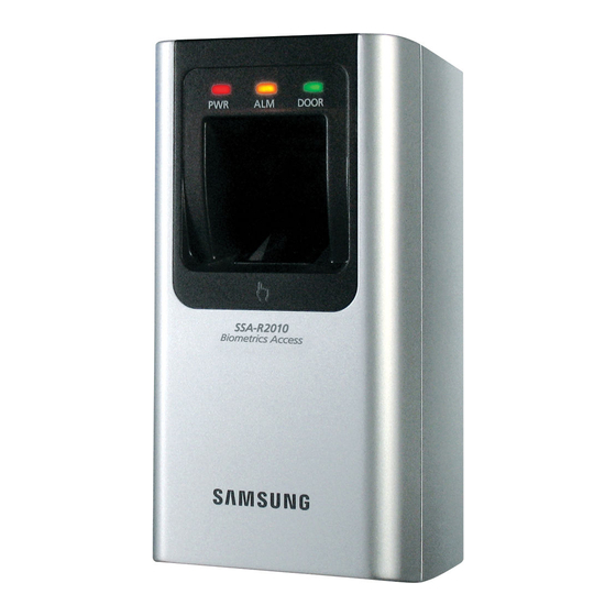
Page 7: At A Glance
AT A GLANCE Front Panel Displays the status of the system operation. Fingerprint Sensor Fingerprint scanner module. Card Recognition Present a card to the marked area, and the product starts reading it. Speaker Sounds a voice comment according to the user manipulation. Englis_ English _ 7... -
Page 8: Rear Panel
product introduction Rear Panel Tamper Switch Tamper switch. Tamper switch. Fixing Screw Hole for a fi xing screw. 6-PIN Connector Can be connected to the Wiegand input and RS-485 communication cables. 8-PIN Connector Can be connected to the Wiegand output and signal output cables. 2-PIN Connector Can be connected to the power cable. -
Page 9: Cable Color Scheme
CABLE COLOR SCHEME ❖ 2-PIN Connector I/O Pins Signal Cable Color Power (+12V) DC +12V Earth-grounding GND (-) Black ❖ 6-PIN Connector I/O Pins Signal Cable Color EX Input Wiegand DATA0 EX-DATA0 Pink EX Input Wiegand DATA1 EX-DATA1 Sky Blue Brown Blue RS-485 A(+) -
Page 10: Cable Selection
product introduction CABLE SELECTION Item Cable Type Power (DC12V) Belden #9409, 18 AWG 2 Conductor, Unshielded Belden #9409, 18 AWG 2 Conductor, Unshielded DC Power Product Wiegand I/O Belden #9512, 22 AWG 4 Conductor, Shielded Product Controller connected Belden #9514, 22 AWG 8 Conductor, Shielded External Reader Product Belden #9512, 22 AWG 4 Conductor, Shielded... -
Page 11: Installation And External Connection
installation and external connection INSTALLING THE WALL MOUNT Use 2 screws to fi x the Wall Mount on an appropriate point. Drill a hole on the center of the Wall Mount so that the cables are arranged through it. Take out the cables through the center hole. Connect the cables to the 4 connectors as appropriate, and use one screw to fi... -
Page 12: Earth-Grounding The Communication Cables
installation and external connection EARTH-GROUNDING THE COMMUNICATION CABLES It is recommended to use a proper grounding system for the communication cables. The best grounding method is to earth-ground the shield wire of the communication cable. However, the earth-grounding of the communication cable is not easy, and it also causes an increased installation cost. There are three grounding points available for installation: 1. -
Page 13: I/O Connection
I/O CONNECTION Overall Wiring Diagram Controller White with red stripes Buzzer Control Blue with white stripes LED Control Gray with red stripes System Mode Control Wiegand Orange with black stripes Authentication Success Orange Authentication Error White DATA1 Green DATA0 DATA DC + 12V Black GND(-) - Page 14 installation and external connection Input Connection Buzzer Control (White with red stripes) LED Control (Blue with white stripes) CONTROLLER System Mode Control (Gray with red stripes) POWER - Connection of External LED control Connect the LED control input line (blue with white stripes) to the NO port of the controller relay output, and GND to the COM port.
- Page 15 Output Connection Authentication Success (orange with black stripes) Authentication Error (orange) CONTROLLER DATA1 (white) DATA0 (green) 12V (red) GND (black) POWER - Wiegand DATA Output Connection Connect the green line (Wiegand DATA 0) of the product to Wiegand DATA 0 of the controller. Connect the white line (Wiegand DATA 1) of the product to Wiegand DATA 1 of the controller.
-
Page 16: Connecting To The External Reader
The product should be connected to GND(-) of the external reader. • For a list of compliant readers (external readers), see the followings: SSA-R2010/SSA-R2020/SSA-R2040 - Standard 26bit Wiegand format proximity reader SSA-R2011 / SSA-R2021 / SSA-R2041 - Standard 34bit Wiegand format proximity reader... -
Page 17: Communication Line Connection
COMMUNICATION LINE CONNECTION RS-485 Communication Port Connection (Standalone) A RS485/RS232 converter is needed to make RS485 communications between the product and the host PC. Please follow the steps below: RS-232 RS-485/RS-232 Con- verter Host PC RS-485 Max. 1200m Gray Yellow Connect the yellow RS485-RTX (+) line to the RS485-A port of the converter. - Page 18 installation and external connection RS-485 Communication Port Connection (Multiple Units) A RS-485/RS-232 converter is needed to make RS-485 communications across a multiple of the products and the host PC. Please follow the steps below: RS-232 RS-485/RS-232 Converter Host PC RS-485 Max.
- Page 19 TCP/IP Communication Port Connection To enable TCP/IP communications with the host PC, you must have connected the RJ45 jack to CON4 (8-PIN connector). Please follow the steps below: Host PC RJ45 RJ45 RJ45 RJ45 Connect the RJ45 jack of the product to the RJ45 plug of the network system. Install and launch the application (SAMS).
-
Page 20: Initializing The System Using The Dip Switch
Initialization INITIALIZING THE SYSTEM USING THE DIP SWITCH Initialize the system using the DIP switch on the rear of the product. Disconnect the power supply. KSD82H Position the DIP switch on the rear of the product to ON (upside) and apply power to the product. -
Page 21: Display And Operation Status Of Reader/Register
DISPLAY AND OPERATION STATUS OF READER/REGISTER LED ON : LED Blinking : LED ON : LED OFF : LED Blinking : Beep Voice Message Description PWR OK ERR PWR OK WELCOME TO ACCESS The product is in the boot process after it 1 BEEP turned on. -
Page 22: To Register/Delete The Master Id (Card)
initialization TO REGISTER/DELETE THE MASTER ID (CARD) The product will switch to Registration mode when presented with the master card in Reader mode. The product will switch to Reader mode when presented with the master card in Registration mode. If you want to register a new master card, initialize the system before proceeding. Refer to “Initializing the system using the DIP switch”. -
Page 23: Reader Mode And Authentication
READER MODE AND AUTHENTICATION Reader Mode In Reader mode, any recognized user ID or status will be transmitted to the controller. If the user ID and fi ngerprint are authenticated, the corresponding card ID will be displayed. If they are not authenticated, an error signal will be output. How to get authenticated if set to RF Only mode or if registered in RF Only mode Present the registered card to the reader. -
Page 24: User Management
User Management REGISTERING THE ID Check if the green and orange indicators are all turned off when the reader turns on. Present the master card to the reader. You will hear the following REGISTRATION AND voice message with the green and orange indicators blinking. DELETION MODE, SCAN YOUR CARD Present a user card to the reader. -
Page 25: To Delete Id
TO DELETE ID Check if the green and orange indicators are all turned off when the reader turns on. Present the master card to the reader. You will hear the following REGISTRATION AND voice message with the green and orange indicators blinking. DELETION MODE, SCAN YOUR CARD Present a registered user card to the reader. -
Page 26: Output Format
Output Format WIEGAND OUTPUT (DEFAULT) Timing Diagram 100us DATA-0 DATA-1 *n : 34 or 26 LOGIC Data Type (26-bit /34-bit) • Even parity bits from Bit 2 to Bit 13 / Bit 2 to Bit 17 • Bit 2 to Bit25 / Bit 2 to Bit33 : 3-byte ID number / 4-byte ID number •... -
Page 27: Other Information
Other Information HOW TO REGISTER THE FINGERPRINT Correct Fingerprint Registration Fingerprint Successful 1:1/1:N scanning Authentication Incorrect Fingerprint Registration Fingerprint 1:1/1:N Authentication Scanning Error In case of failures of fi ngerprint recognition • Moist Fingerprint • Dry Fingerprint • Stained Fingerprint •... - Page 28 TROUBLESHOOTING If the product does not function properly, please see the below for trouble shooting. If the trouble persists, please contact the SAMSUNG Customer Service near you. Problem Action If you fail to enter registration mode using 1) Check if the master card is invalid.
- Page 29 Problem Action My reader does not communicate 1) Please check the settings of the application software and the controller. with the host PC. - Check if the product COMM ADDR is recognized by the application software. - Set the different COMM ADDR when two or more devices are installed. - Check the followings when in serial communications.
-
Page 30: Product Specifications
product specifi cations PRODUCT SPECIFICATIONS SSA- SSA- SSA- SSA- SSA- SSA- Item R2010 R2020 R2040 R2011 R2021 R2041 Fingerprint Users 1,000 2,000 4,000 1,000 2,000 4,000 Fingerprint Templates Size 800Bytes for 2 Fingerprint Templates Power / Current DC 12V / Max.290mA DC 12V / Max.310mA External Reader Port 1ea : 26bit External Reader Port 1ea : 34bit... - Page 31 Correct Disposal of This Product (Waste Electrical & Electronic Equipment) (Applicable in the European Union and other European countries with separate collection systems) This marking on the product, accessories or literature indicates that the product and its electronic accessories (e.g. charger, headset, USB cable) should not be disposed of with other household waste at the end of their working life.