Table of Contents
Advertisement
Quick Links
GAS FURNACE SAFETY................................................................1
INSTALLATION REQUIREMENTS ................................................3
Tools and Parts ............................................................................3
Location Requirements................................................................3
Installation Configurations ...........................................................4
Airflow Conversion .......................................................................5
Duct Work Requirements.............................................................8
Electrical Requirements ...............................................................9
Gas Supply Requirements ...........................................................9
Venting Requirements..................................................................9
INSTALLATION INSTRUCTIONS ................................................10
Inspect Shipment .......................................................................10
Plan Vent System .......................................................................10
Determine Vent Pipe Direction...................................................12
We have provided many important safety messages in this manual and on your appliance. Always read and obey all
safety messages.
This is the safety alert symbol.
This symbol alerts you to potential hazards that can kill or hurt you and others.
All safety messages will follow the safety alert symbol and either the word "DANGER" or
"WARNING." These words mean:
All safety messages will tell you what the potential hazard is, tell you how to reduce the chance of injury, and tell you
what can happen if the instructions are not followed.
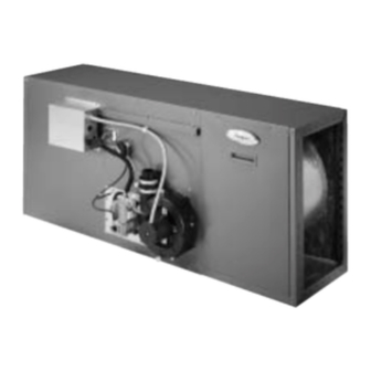
Model WFCH
46889B003
90 HORIZONTAL GAS FURNACE
INSTALLATION INSTRUCTIONS
Table of Contents
GAS FURNACE SAFETY
Your safety and the safety of others are very important.
Whirlpool
Plantation, Florida 33324
Connect Venting.........................................................................14
Install Condensate Disposal.......................................................14
Install Duct Work ........................................................................15
Filter Specifications ....................................................................15
Make Electrical Connections .....................................................16
Make Gas Connections..............................................................16
Check the Furnace Input Rate ...................................................17
Adjust the Furnace Input Rate ...................................................17
Complete Installation..................................................................18
Sequence of Operation ..............................................................19
Controls ......................................................................................20
TROUBLESHOOTING ..................................................................20
ASSISTANCE OR SERVICE .........................................................23
Accessories ................................................................................23
You can be killed or seriously injured if you don't
immediately follow instructions.
You can be killed or seriously injured if you don't
follow instructions.
®
Home Cooling and Heating
7901 S.W. 6th Court
Advertisement
Table of Contents

Related Manuals for Whirlpool WFCH


Summary of Contents for Whirlpool WFCH
-
Page 1: Table Of Contents
All safety messages will tell you what the potential hazard is, tell you how to reduce the chance of injury, and tell you what can happen if the instructions are not followed. Whirlpool ® Home Cooling and Heating 7901 S.W. 6th Court Model WFCH Plantation, Florida 33324 46889B003... -
Page 2: Save These Instructions
IMPORTANT SAFETY INSTRUCTIONS Use only with type of gas approved for this furnace. When a furnace is installed so that supply ducts Refer to the furnace rating plate. carry air circulated by the furnace to areas outside the space containing the furnace, the return air Install this furnace only in a location and position shall also be handled by duct(s) sealed to the as specified in the Location Requirements section... -
Page 3: Installation Requirements
Location Requirements INSTALLATION REQUIREMENTS These instructions are intended as a general guide only for use by qualified persons and do not supersede any national or local codes in any way. Compliance with all local, state, or national codes pertaining to this type of equipment should be determined prior to installation. -
Page 4: Installation Configurations
All models are suitable for closet or utility room installation. Suspended Installation Requirements Utility room installation requires: A door opening large enough for the widest part of the These models may be installed as suspended units. These furnace. furnaces are not designed for direct attachment of suspension A door opening large enough to remove/replace any other rods to the furnace casing. -
Page 5: Airflow Conversion
Airflow Conversion This furnace is factory assembled for right to left airflow. It can be converted to left to right airflow. The conversion should be made WARNING prior to installing the unit. IMPORTANT: The sides are identified as the original component side and the new component side. - Page 6 12. Remove the manifold cover (2 screws), and burner access 15. Remove the 2 screws securing the burner locking tab behind cover (6 screws). Do not remove the screws located in the 2 the burner access cover. clearance holes. The rubber grommet remains on the burner NOTE: The flange is located toward the inside.
- Page 7 21. Install both locking tabs, using 2 screws, flange side toward 24. Install the burner access cover (6 screws) and manifold cover the burners with the flange facing out toward the blower end (2 screws), making sure the covers seal around the manifold of the furnace.
-
Page 8: Duct Work Requirements
After Conversion (new component side) 1. Burner access panel 6. Control box bushing 11. Blower wire bushing 16. Manifold cover 2. Pressure tap 7. Primary limit switch 12. Blower door interlock switch 17. Gas control valve 3. Pressure switch tubing 8. -
Page 9: Electrical Requirements
Electrical Requirements Venting Requirements Adequate provisions for combustion air and ventilation of furnace WARNING must be made. Refer to the National Fuel Gas Code, ANSI Z223.1/NFPA54 (latest edition), Natural Gas and Propane Installation Codes (latest editions), or applicable provisions of the local building codes. -
Page 10: Installation Instructions
Plan Vent System INSTALLATION The high efficiency of this furnace is accomplished by the INSTRUCTIONS removal of both sensible and latent heat from the flue gases. The removal of latent heat results in the condensation of moisture in the flue gases. This condensation occurs in the secondary heat exchanger and in the vent system. - Page 11 Materials Vent Pipe Size and Length All pipe, fittings, primer, and solvent cement must conform The vent pipe and air intake pipe should be sized in accordance with American National Standard Institute and the American with the information found in the “Vent Tables.” One 90° elbow is Society for Testing and Materials (ANSI/ASTM) standards.The equivalent to 5 ft of pipe.Two 45°...
-
Page 12: Determine Vent Pipe Direction
Vent Table - 100,000 BTU/HR Models Determine Vent Pipe Direction Vent Pipe Minimum Pipe Diameter (in.) Length (ft) The vent system of the furnace must be self-supporting and must not apply any weight load to the combustion blower. 2.5 2.5 Vertical Venting A vertical vent should extend through the roof a minimum of 2 ft 2.5 2.5 2.5... - Page 13 Horizontal Venting Existing Venting Systems Run Pitch = 1/4" Per Ft. Min. When an existing furnace is removed or replaced, the original venting system may no longer be sized to properly vent the attached appliances. An improperly sized venting system can 18"...
-
Page 14: Connect Venting
2. Glue the ¹⁄₂ in. 90° PVC street elbow (supplied) to the trap Connect Venting (supplied). Be sure to glue it so that the trap outlet will be oriented in the desired direction for drainage. 1. Run venting to the furnace, see “Plan Vent System.” NOTE: When the furnace is installed in an attic, above a 2. -
Page 15: Install Duct Work
Install Duct Work Filter Specifications IMPORTANT: Install duct work in accordance with NFPA 90B Filters are not supplied with these furnaces; however, filters must and any local codes. be used. It is the installer’s responsibility to install a filter rack with the duct work and to install properly sized filters in accordance When the furnace is installed so that the supply ducts carry with the “Minimum Filter Requirements Chart.”... -
Page 16: Make Electrical Connections
Make Electrical Connections WARNING WARNING Electrical Shock Hazard Electrically ground furnace. Electrical Shock Hazard Connect ground wire to green pigtail lead. Disconnect power before servicing. Failure to do so can result in death or electrical shock. Replace all parts and panels before operating. 6. -
Page 17: Check The Furnace Input Rate
Check the Furnace Input Rate WARNING (if required) FIRE OR EXPLOSION HAZARD IMPORTANT: Failure to follow the safety warnings exactly could result The furnace input rate must not exceed the input rating on in serious injury, death or property damage. the furnace rating plate. -
Page 18: Complete Installation
6. Turn on the electrical power to the furnace. Complete Installation 7. Set the room thermostat to a point above room temperature to light the main burners. IMPORTANT: Do not use this furnace if any part has been under 8. Observe the pressure reading on the pressure gauge. water. -
Page 19: Sequence Of Operation
Adjust Blower Speed Sequence of Operation WARNING Heating A call for heat from the thermostat closes R to W on the blower control board, which begins the ignition sequence. The induced draft blower output energizes. The pressure switch senses normal combustion airflow, and closes. After a 15-second pre- purge, the control energizes the hot surface igniter. -
Page 20: Controls
Controls TROUBLESHOOTING Pressure Switch Furnace Fails to Operate Properly The pressure switch is a normally open switch that monitors combustion airflow. If there is adequate airflow, the pressure Review “Sequence of Operation” and visually inspect the switch closes. Inadequate airflow resulting from excessive following before troubleshooting: venting system restriction or a failed combustion blower will Is the power to the furnace on? - Page 21 Wiring Connection Diagram - Honeywell ® SmartValve II ® Ignition System LINE VOLTAGE - FACTORY LINE VOLTAGE - FIELD LOW VOLTAGE - FACTORY LOW VOLTAGE - FIELD ROLLOUT ROLLOUT HIGH INDUCED SWITCH SWITCH LIMIT DRAFT (IF USED) BLOWER PRESSURE SWITCH SMARTVALVE LIMIT LIMIT...
- Page 22 Wiring Schematic - Honeywell ® SmartValve II ® Ignition System EAC(S) NEUTRALS (IF USED) INTERLOCK SWITCH CLEANER CONSTANT NEUTRALS HEAT CIRCULATION COOL NEUTRALS INDUCED HUMIDIFIER DRAFT BLOWER SMVII (IF USED) IGNITION CONTROL IGNITER (120 VAC) NEUTRALS 120 VAC TRANSFORMER 24 VAC BLOWER CONTROL CENTER T’STAT CONDENSER...
-
Page 23: Assistance Or Service
7901 S.W. 6th Court Plantation, Florida 33324 Please include a daytime phone number in your correspondence. Accessories To order accessories ask for the appropriate part number listed below or contact your authorized Whirlpool ® Home Cooling and Heating dealer. ALPKT572-2... - Page 24 Honeywell and SmartValve are trademarks of Honeywell International, Inc. 46889B003 ®/TM Whirlpool and all other trademarks are owned by Whirlpool, U.S.A., 2/03 © 2003. All rights reserved. used under license by Tradewinds Distributing Company, LLC. Printed in U.S.A.
Need help?
Do you have a question about the WFCH and is the answer not in the manual?
Questions and answers