Table of Contents
Advertisement
NOTE:
Please read all instructions
carefully before using this
product
Table of Contents
Safety Notice
Hardware Identifier
Assembly Instruction
Parts List
Resistance Chart
Warranty
Ordering Parts
Model
AX-2109.1
Retain This
Manual for
Reference
100506
OWNER'S
MANUAL
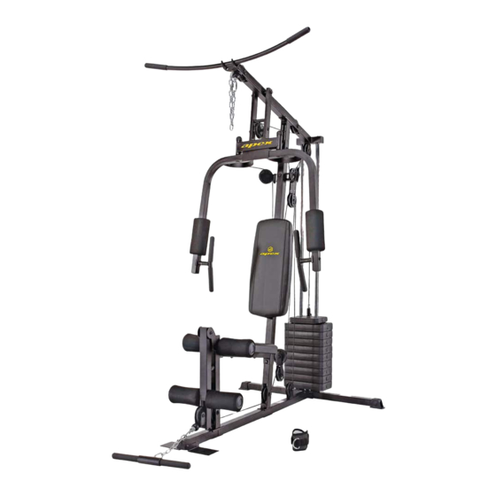
APEX Home Gym
14777 DON JULIAN RD., CITY OF INDUSTRY, CA 91746
Tel: (800) 999-8899 Fax: (626) 961-9966
www.impex-fitness.com
info@impex-fitness.com
AX-2109.1
®
IMPEX
INC.
Advertisement
Table of Contents

Subscribe to Our Youtube Channel
Related Manuals for Impex APEX AX-2109.1


Summary of Contents for Impex APEX AX-2109.1
- Page 1 AX-2109.1 Assembly Instruction Parts List Resistance Chart Warranty Ordering Parts Model AX-2109.1 Retain This Manual for Reference 100506 OWNER'S ® IMPEX INC. MANUAL 14777 DON JULIAN RD., CITY OF INDUSTRY, CA 91746 Tel: (800) 999-8899 Fax: (626) 961-9966 www.impex-fitness.com info@impex-fitness.com...
-
Page 2: Table Of Contents
ORDERING PARTS..................………… 22 BEFORE YOU BEGIN ® Thank you for selecting the APEX AX-2109.1 HOME GYM by IMPEX FITNESS PRODUCTS. For your safety and benefit, read this manual carefully before using the machine. As a manufacturer, we are committed to provide you complete customer satisfaction. If you have any questions, or find there are missing or damaged parts, we guarantee you complete satisfaction through direct assistance from our factory. -
Page 3: Important Safety Notice
PHYSICIAN. THIS IS ESPECIALLY IMPORTANT FOR INDIVIDUALS OVER THE AGE OF 35 OR PERSONS WITH PRE-EXISTING HEALTH PROBLEMS. READ ALL INSTRUCTIONS BEFORE USING ANY FITNESS EQUIPMENT. IMPEX INC. ASSUMES NO RESPONSIBILITY FOR PERSONAL INJURY OR PROPERTY DAMAGE SUSTAINED BY OR THROUGH THE USE OF THIS PRODUCT. -
Page 4: Warning Label Placement
WARNING LABEL PLACEMENT The warning labels shown here have been placed on the Rear Base and Upper Frame. If the labels are missing or illegible, please call customer service at 1-800-888-8899 for replacements. Apply the labels in the location shown. -
Page 5: Hardware Pack
HARDWARE PACK NOTE: The following parts are not drawn to scale. Please use your own ruler to measure the size. - Page 6 HARDWARE PACK NOTE: The following parts are not drawn to scale. Please use your own ruler to measure the size.
- Page 7 HARDWARE PACK...
-
Page 8: Assembly Instructions
ASSEMBLY INSTRUCTION Tools Required for Assembling the Machine: Two Adjustable Wrenches, two Allen Wrenches, and one Philips Screwdriver. NOTE: It is strongly recommended this machine to be assembled by two or more people to avoid possible injury. STEP 1 (See Diagram 1) A.) NOTE: Do not tighten all the Nuts and Bolts until instructed to do so. - Page 9 DIAGRAM 1...
- Page 10 STEP 2 (See Diagram 2) A.) Slide two Ø2 ½” x 1” Rubber Bumpers (#65) onto the Guide Rods. B.) Slide 11 Weight Plates (#33) onto the Guide Rods. Make sure the deep grooves on the Weight Plates are all facing the back of the machine and downward. Insert the Selector Rod (#17) through the center hole on the Weight Plates.
- Page 11 DIAGRAM 2...
- Page 12 STEP 3 (See Diagram 3) A.) Attach the Front Press Base (#11) to the Upper Frame (#4). Secure it with one Long Axle (#46), two Ø ¾” Washers (#83), and two M10 Aircraft Nuts (#85). B.) Attach the Right Butterfly (#6) to the Front Press Base (#11). Secure it with one Ø 1 ½” Washer (#82), one M6 x 1 ¼”...
- Page 13 STEP 4 (See Diagram 4) A.) Attach the Leg Developer (#7) to the bracket on the Leg Developer Holder (#1). Secure it with a Leg Developer Axle (#47), two M10 x 5/8” Allen Bolts (#74), and two Ø ¾” Washers (#83).
- Page 14 CABLE LOOP DIAGRAM...
- Page 15 STEP 5 (See Diagram 5 & Cable Loop Diagram) A.) Attach the 138” Upper Cable (#35) to the opening at the front of the Upper Frame (#4). Note: The Ball Stopper on the cable should be underneath the Frame. B.) Attach a Pulley (#63) to the opening. Secure it with one M10 x 2 3/8” Allen Bolt (#71), two Pulley Bushings (#50), and one M10 Aircraft Nut (#85).
- Page 16 DIAGRAM 5...
- Page 17 STEP 6 (See Diagram 6 & Cable Loop Diagram) A.) Attach one end of the 119” Butterfly Cable (#37) to the hook on the Right Butterfly (#6). B.) Draw the Cable to the right Swivel Pulley Bracket (#21). C.) Attach a Pulley to the bracket. Secure it with one M10 x 2” Allen Bolt (#87), two Cable Retainers (#89), two Ø...
- Page 18 STEP 7 (See Diagram 7 & Cable Loop Diagram) A.) Attach the 128” Lower Cable (#36) to the open bracket on the bottom of the Leg Developer (#7). Note: The Ball Stopper on the cable should be in front of the pulley not on top.
- Page 19 DIAGRAM 7...
-
Page 20: Exploded Diagram
EXPLODED DIAGRAM... -
Page 21: Parts List
PARTS LIST KEY NO. DESCRIPTION Q’ty Leg Developer Holder Bottom Label Rear Base Frame Handle Grip Lower Vertical Frame C-clip Upper Frame Manual Left Butterfly Rear Base Frame End Cap Right Butterfly 1 5/8” x ¾” End Cap Leg Developer 1 ¾”... -
Page 22: Resistance Chart
AX-2109.1 WEIGHT RESISTANCE CHART Weight Plate Front Press Butterfly Lat Pull Low Pulley Note: Each plate weights 10 lbs. Numbers are approximate. Actual weights may vary. Values for Butterfly are for each arm. -
Page 23: Warranty
IMPEX Customer Service Department at 1-800-999-8899. All freights on products returned to IMPEX must be prepaid by the customer. This warranty does not extend to any product or damage to a product caused by or attributable to freight damage, abuse, misuse, improper or abnormal usage or repairs not provided by an IMPEX authorized service center or for products used for commercial or rental purposes.
Need help?
Do you have a question about the APEX AX-2109.1 and is the answer not in the manual?
Questions and answers
Hi, just wondering if you can still buy parts for AX-2109.1 home gym. spacificly #35,#36,#37 cables? thanks Pat