
Related Manuals for Riello RDB3 CF 489T50


Summary of Contents for Riello RDB3 CF 489T50
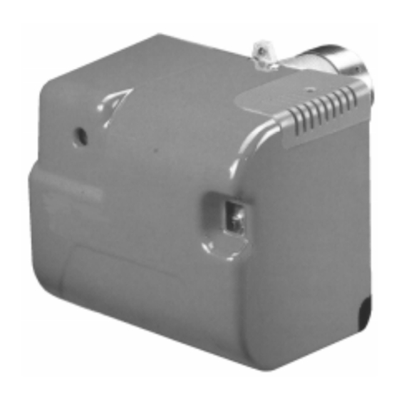
- Page 1 Installation, use and maintenance instructions Kerosene and gas oil burners One stage operation CODE MODEL TYPE 3748950 RDB3 CF 489T50 3748850 RDB4 CF 488T50 2902587 (2)
-
Page 3: Table Of Contents
INDEX BURNER DESCRIPTION ... . WORKING ..... . . 1.1 Burner equipment ....4.1 Combustion adjustment. -
Page 4: Technical Data
TECHNICAL DATA 2.1 TECHNICAL DATA TYPE 489 T50 488 T50 3.0 – 5.8 kg/h 4.7 – 9.5 kg/h Output – Thermal power 35.6 – 68.7 kW 55.7 – 113 kW (with air at 20 °C) (H i = 11.97 kWh/kg) Kerosene, viscosity 1.6 –... -
Page 5: Installation
INSTALLATION 3.1 BOILER FIXING Put on the flange (1) the screw and two nuts, (see fig. 2). Widen, if necessary, the insulating gasket holes (5), (see fig. 3). Fix the flange (1) to the boiler door (4) using screws (2) and ( if necessary ) the nuts (3) interposing the insulating gasket (5) , (see fig. -
Page 6: Hydraulic Systems
3.3 HYDRAULIC SYSTEMS Fig. 5 WARNING: The pump is designed to allow working with one pipe. In order to obtain two pipes working it is necessary to unscrew the return plug (2), screw the by-pass screw (3) and then screw again the plug (2). (See fig. 5). In the two pipes systems, before starting the burner make sure that the return pipe-line is not clogged. -
Page 7: Electrical Wiring
3.4 ELECTRICAL WIRING NOTES: WARNING – Wires of min. 1 mm section. DO NOT EXCHANGE NEUTRAL WITH PHASE (Unless requested otherwise by local stand- ards and legislation). 50Hz - 230V – The electrical wiring carried out by the install- er must be in compliance with the rules in force in the Country. -
Page 8: Working
4. WORKING 4.1 COMBUSTION ADJUSTMENT In conformity with Efficiency Directive 92/42/EEC the application of the burner on the boiler, adjustment and testing must be carried out observing the instruction manual of the boiler, including verification of the CO and concentration in the flue gases, their temperatures and the average temperature of the water in the boiler. To suit the required appliance output, choose the proper nozzle and adjust the pump pressure, the setting of the combustion head, and the air damper opening in accordance with the following schedule. -
Page 9: Electrodes Setting
MAINTENANCE POSITION ACCESS TO THE COMBUSTION HEAD, ELECTRODES AND NOZZLE (see fig. 10). Remove the burner out of the boiler, after loosing the fixing nut to the flange. Hook the burner to the flange (1), by removing the blast tube (2) after loosing the fixing screws (3). Remove the electrodes assembly (5) from the nozzle holder (4) after loosing its fixing screw (A, fig. -
Page 10: Combustion Head Setting
4.4 COMBUSTION HEAD SETTING This is done when fitting the nozzle, with the blast tube removed. It depends on the output of the burner and is carried out by rotating the regulating rod, till the terminal plane of the blast tube is level with the set-point, as indicated in the schedule. -
Page 11: Faults / Solutions
FAULTS / SOLUTIONS Here below you can find some causes and the possible solutions for some problems that could cause a failure to start or a bad working of the burner. A fault usually makes the lock-out lamp light which is situated inside the reset button of the control box (3, fig.
Need help?
Do you have a question about the RDB3 CF 489T50 and is the answer not in the manual?
Questions and answers