Table of Contents
Advertisement
Advertisement
Table of Contents

Related Manuals for Beta Enduro RR 250 2016


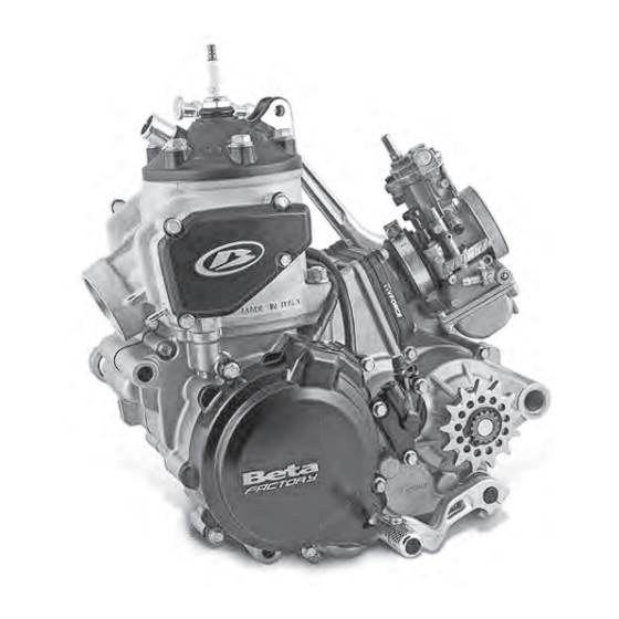
Summary of Contents for Beta Enduro RR 250 2016
-
Page 2: Table Of Contents
TABLE OF CONTENTS 2.9.2 left cRankcase half ................. 40 MOTOR CHECKS ANd ASSEMBLy CRANKCASE HALF ..............41 3.1.1 application of Right cRankcase half paRts ....42 3.1.2 application of left cRankcase half paRts ......44 CHECK OF CONNECTING ROD AND MOTOR SHAFT ..45 ASSEMbLING OF COMPLETE CRANKSHAFT ......46 GEAR UNIT: CHECKS AND REASSEMbLY ......47 3.4.1... - Page 3 TABLE OF CONTENTS 3.13 CHECK OF INTAKE UNIT AND ASSEMbLY ......95 3.14 INSERTION OF CLUTCH ROD AND PINION SPACER ..97 REASSEMBLy OF MOTOR IN vEHICLE TABLE OF FASTENING TORQUES OF ENGINE COMPONENTS TABLE OF FRAME/MOTOR FASTENING TORQUES TABLE OF SUPERSTRUCTURE FASTENING TO RQUE vALUES RECOMMENdEd MOTOR MAINTENANCE RECOMMENdEd LUBRICANTS ANd LIQUIdS...
-
Page 4: Preamble
www.betamotor.com PREAMBLE This publication has been written in order to make operations for inspection, maintenance and repairs of the motorcycle engine known and understandable to the user of the motorcycle and to the technical assistance operator. Read this entire manual with care before operating on the engine. Sufficient knowledge of the compo- nents that make up the engine and of all the procedures to be followed for inspection and maintenance contribute to lengthen the life of the engine. - Page 5 www.betamotor.com • Coolant liquid Coolant contains dangerous substances which are harmful for the environment. When chang- • In some situations, the ethylene glycol con- ing it, you must be equipped to dispose of it in tained in the coolant is flammable and its flame compliance with existing law.
-
Page 6: Technical Features Of Engine
www.betamotor.com TECHNICAL FEATURES OF ENGINE CHARACTERISTIC dATA ENGINE RR250 RR300 Bore[mm]/Stroke [mm] 66,4/72 72/72 Displacement [cm³] Compression ratio 13,5:1 11,5:1 TRANSMISSION RR250 RR300 Main 28/70 28/70 1st gear ratio 12/31 12/31 2nd gear ratio 15/28 15/28 3rd gear ratio 19/28 19/28 4th gear ratio 20/24... -
Page 7: Special Equipment
www.betamotor.com SPECIAL EQUIPMENT Symbols Crankcase uncoupler code 0100042 000 Clutch drum nut/Main tool code 026140010 000 Crankcase/Cylinder gasket check plate code 026140020 000 Value Front bracket code 026140030 000 to fix engine to stand code Fastening torque 3625132 000 Flywheel blocking tool code 026140040 000 Flywheel extractor code 3625173 000 Engine support stand code 3625132 000 Loctite 243/ Sichel 100M Pasta siliconica Grease... -
Page 8: Removal Of Motor From Vehicle
REMOvAL OF MOTOR FROM vEHICLE • Carefully wash the vehicle; • Remove the engine guard plate; • Place the vehicle onto an adequate stand. • Disconnect the tank ventilation pipe. • Set the fuel valve to OFF and disconnect the fuel pipe from the valve. - Page 9 • Remove the tank along with the sides. • Remove the frame guards 3 (one each side) and the pinion guard 4. • Remove the circlip 5 and extract the pinion. Rest the chain against the upper wedge 6. • Remove the screws 7 fixing the clutch actua- tor to the crankcase half.
- Page 10 • Remove the exhaust expansion and the silen- cer. • Drain the cooling system through screw 8 and let the liquid outflow into a container (the co- oling circuit contains 1.3l of liquid). Remove the radiator cap. • Disconnect the water hoses from the engine and from the right radiator.
- Page 11 • Disconnect the spark plug cap, the connec- tors from the coil and remove the coil itself. Cut all straps binding the engine’s electric system to the clutch pipe and to the frame. • Disconnect the engine ventilation pipes • Pull the mixer tube 9 out from the intake ma- nifold and tube hold 10.
- Page 12 • Remove the start motor cable fixing nut. • Remove the head connections and spark plug. • Release and remove the brake pedal return spring 7. Remove the kickstarter lever. • Remove the gear lever.
- Page 13 • Loosen the carburetor straps from the air fil- ter sleeve and from the manifold. • Remove the seat rail lower fixing screws 12 (one each side) and loosen the upper screws 13 (one each side). • Rotate the filter box unit. •...
- Page 14 • Remove the swingarm pin 14 and the upper shock-absorber pin 15. • Remove the engine pins 16. Extract the engine from the frame and apply it to the specific stand code 3625132 000 using spe- cific front fixing bracket code 026140030 000.
-
Page 15: Engine Disassembly
ENGINE dISASSEMBLy Secure the engine to the specific support stand code 3625132000 by means of front fixing code. 026140030 000, in order to work in comfort and safety. Then proceed as follows CLUTCH/GEAR OIL dRAIN Remove screw 1 and let the oil drain. REMOvAL CLUTCH CONTROL ROd ANd PI-... -
Page 16: Removal Of Piston, Cylinder And Head
REMOvAL PISTON, CyLINdER ANd HEAd Remove the spigot screws 1 together with the copper washers. Remove the head and the two O-rings. Remove the four screws 2. Remove the three screws 3 and cover 4. - Page 17 Release the lock 5 and remove it. Release the control rod 6. Remove the gasket 7. It may be necessary to force the rubber gasket 8 slightly; place a metal pin A between the lever and the gasket 8 and force it externally slightly.
- Page 18 Remove the four collar nuts 9. Extract the cylinder and base gaskets. ATTENTION! Place a clean cloth between the piston and the crankcase to keep foreign objects or simple solid residue from falling inside the base. Remove the circlip 10 by gripping it with a pair of fine nose pliers A. Removal of piston circlip. Push the pin bolt with an aluminium cylinder (or similar) b, until the pin bolt is released from the connecting rod foot...
-
Page 19: Removal Of Ignition Unit
REMOvAL IGNITION UNIT The ignition unit is made up of the flywheel (or rotor), the pick-up and the stator which is one with the flywheel cover. 2.4.1 Removal of flywheel cover Remove the five screws 1 fastening the flywheel cover 2 to the left crankcase. Remove the flywheel cover and the gasket placed between the crankcase and the cover. -
Page 20: Removal Of Pick-Up
2.4.3 Removal of flywheel Block the flywheel using special tool A (code 026140040 000) and remove the fastening nut securing the flywheel to the crankshaft. NOTE: Once the nut has been unscrewed, pay attention to the special elastic washer placed between the nut and the flywheel. Removal of flywheel nut. To remove the flywheel, tighten the extractor b (code 3625173) onto the threaded part on the flywheel. -
Page 21: Removal Of Electric Ignition
REMOvAL ELECTRIC IGNITION The electric ignition is carried out by means of start motor 1 that meshes on the Bendix coupling 4. The coupling gear axially shifts and meshes onto the ring gear which is one with the flywheel, due to the start motor rotation. -
Page 22: Removal Of Start Motor
2.5.1 Removal of start motor Remove the two screws 1 and extract the motor itself. Removal of start motor. 2.5.2 Removal of bendix cou- pling Extract the Bendix coupling 1 once the complete flywheel cover and flywheel itself (see par. 2.4.1), have been removed. -
Page 23: Removal Of Coolant Liquid Pump, Clutch Unit
REMOvAL OF COOLANT LI- QUId PUMP, CLUTCH UNIT, MAIN GEAR, CENTRIFU- GAL UNIT, GEARSHIFT OR- GANS, KICKSTART Remove the cover 1 by loosening the four screws 2, to access the coolant liquid pump. Note: remove the coolant liquid pump impeller if having to intervene on the centrifugal unit. - Page 24 Remove the outer clutch cover 3 by loosening the five screws 4, to access the clutch unit only. Outer clutch cover screws.
- Page 25 When doing a complete overhaul of the engine or of gearshift organs, kickstart, main transmission or centrifugal unit, the inner clutch cover 5 must be removed by loosening the nine screws 6. Inner clutch cover screws. Pay attention to the two reference pins A placed between the right crankcase half and the inner clutch cover while disassembling.
-
Page 26: Removal Of Coolant Liquid Pump
2.6.1 Removal of coolant liquid pump Loosen fixing screw 1 once the coolant liquid pump cover has been removed. cooling pump fixing screw. Extract the impeller 2 and the thrust 3. Removal of impeller. Extract the complete pump body 4 and remove gasket 5. -
Page 27: Removal Of Centrifugal Unit And Leverage
2.6.2 Removal of centrifugal unit and leverage Access the centrifugal unit and leverage by removing the inner clutch cover. Disassemble the adjustment cover 1 by removing the two screws 2, once the pump impeller has been removed (par. 2.6.1). Removal of centrifugal adjustment cover. Remove the unit consisting of adjusting 3 and auxiliary 4 springs and the spring guide 5. - Page 28 Extract the rocker arm complete of control rod and gasket 8, once the screw fixing the rocker arm 6 to the centrifugal control lever 7 has been removed. Disassembly of control rod-rocker arm unit. Extract the centrifugal control lever 7 together with the two thrust washers 9.
- Page 29 Extract the complete centrifugal unit 10. Extraction of centrifugal unit. 1) control cover; 3) Adjusting spring; 4) Auxiliary spring; 5) Spring guide; 6) Rocker arm; 7) centrifugal control lever; 8) Gasket; 9) Thrust washers; 10) centrifugal unit.
-
Page 30: Removal Of Main Gear And Clutch Unit
2.6.3 Removal of main gear and clutch unit Remove the four screws 1 fastening the clutch cap 2 to the clutch drum. Remove the clutch cap together with the four washers and relative springs. clutch cap 2 and four screws 1. Extract the whole pressure plate unit 3 and the clutch disc pack. - Page 31 In order to complete the disassembly of the clutch unit, open the safety washer 4 using a chisel or similar tool and remove the nut 5. Opening of the safety washer with chisel. To unscrew the nut 5, the clutch drum must be blocked with a relevant tool A (code 026140010 000).
- Page 32 Using the main special tool A (code 026140010 000), disassemble the nut fastening the main gear 6 to the crankshaft. NOTE: the clutch case must be in its seat to be able to disassemble the main gear. Attention! The nut must be turned clockwise Remove the washer 7, the case 8, the roller cage 9 Disassembly of the main gear nut.
-
Page 33: Pedal Kickstart
2.6.4 Pedal kickstart The kickstarter is made up of the pedal which, attached to the kickstarter shaft 1, moves the kickstarter gear 2. This gear moves the idler wheel 3 which then meshes with the clutch case. The device moves back thanks to the spring 4. kickstarter mechanism. - Page 34 Using a pair of pliers, pull the end A of the spring 4 from the hole on the crankcase and bring it to a rest position having it turn anti-clockwise. Release of spring from crankcase. Turn the shaft anti-clockwise and pull it off together with the sleeve 9, the spring 10 and the thrust washer 11.
-
Page 35: External Gearshift Unit
2.6.5 External gearshift unit The external gearshift is made up of the drive shaft 1 upon which the movable and fixed pawls are applied. The fixed pawl constitutes the guide of the movable pawl which has the task of engaging the stop cam 2. -
Page 36: Intake System
INTAKE SySTEM The intake system mainly consists of the intake manifold 1 and reed valve 2 and the spacer 3. 1) Intake manifold; 2) complete reed valve; 3) Spacer. Disassemble by removing the four screws 4 fastening the intake manifold and the reed valve to the crankcases. -
Page 37: Gearshift
CRANKSHAFT, GEARBOx UNIT ANd INTERNAL GE- ARSHIFT To access the crankshaft, gearbox unit and internal gearshift, the left and right crankcases must be detached. Here are the needed instructions. 2.81 Opening of crankcase Remove thirteen screws 1fastening crankcases. Attention! Loosen the two equipment fixing screws Removal of crankcase screws. Apply special tool b to the right crankcase half following the punching on the tool itself. -
Page 38: Motor Shaft
2.8.2 Motor shaft The crankshaft 1 can be pulled out by hand. Delicately hit the crankshaft far right in case of resistance. Removal of crankshaft. 2.8.3 Internal gearshift unit and complete gearbox The internal gearshift unit is made up of the desmodromic device 1 upon which the fork 2 and two forks 3 are engaged. -
Page 39: Disassembly Of Parts From Crankcases
Extract the forks together with the drive bushes 5. Extraction of forks from gearbox unit. Proceed to extract the complete gearbox unit including the primary 6 and secondary unit 7. Extraction of complete gearbox unit: 6 main unit, 7 sec- ondary unit. - Page 40 kickstart ramp 1), crankshaft spacer 2) (and relative O-ring), oil seal 3). Remove the desmodromic control bearing seal screw 4 from the inner side. Bearing safety screw.
- Page 41 The bearings 5, 6, 7, 8 and 9 are removed from the outside to the inside. Remove fixing screws 10 to disassemble bearing 9. The centrifugal shaft bearing can be removed by using a universal extractor that must rest onto a purposely created metal plate.
-
Page 42: Left Crankcase Half
2.9.2 Left crankcase half Remove the crankshaft oil seal 1, the secondary shaft oil seal 2 and the gearshift shaft oil seal 3 from the external side. Removal of outer side left crankcase half oil seal. The bearings 4, 5, 6 and 8 are removed from the outside to the inside. -
Page 43: Motor Checks And Assembly
MOTOR CHECKS ANd ASSEMBLy Before reassembling the engine, a series of im- portant checks must be carried out to ensure correct functioning of the engine. In order to insert the bearings in the crankcase halves, bring the crankcase halves to a temper- ature of 150°C and keep them at that tempera- ture for 20 minutes. -
Page 44: Application Of Right Crankcase Half Parts
3.1.1 Application right crankcase half parts Apply the bearings 1, 2, 3 and 4 until flush. Block bearing 4 with specific screw, prior depositing of threadlockers. Fasten at 6Nm. placing of right crankcase half bearings. Apply the bearing 5 from the crankcase half external side, until it is flush, and bearing 6 as shown in the drawing. - Page 45 Apply the kickstart ramp 7 and fasten screws 8 at 10Nm, prior depositing of medium strength 10Nm threadlocker. Application of kickstart ramp. Apply the stopping device as follows. Keeping the tightener on the lever 18 facing towards the crankcase half, apply the spacer 17 onto it, by inserting the smaller diameter segment in the lever.
-
Page 46: Application Of Left Crankcase Half Parts
3.1.2 Application of left crankca- se half parts Apply the bearings 1, 2 and 3 from the crankcase half internal side, until flush. Application of left crankcase half bearings. Apply the bearing 4 from the crankcase half external side, as shown in the drawing. Apply the crankshaft oil seal, gear secondary shaft and gearshift shaft. -
Page 47: Check Of Connecting Rod And Motor Shaft
CHECK OF CONNECTING ROd ANd MOTOR SHAFT After having checked the state of wear of the coupling surfaces, check the offset of the half shaft axes (by measuring radial oscillation) by placing the crankshaft in between two tailstocks or similar instrument. Control the maximum measurement variation during a complete turn, using comparators positioned on the coupling surfaces with the crankshaft bearings. -
Page 48: Assembling Of Complete Crankshaft
ASSEMBLING OF COMPLE- TE CRANKSHAFT When all the aforementioned checks have been carried out and the worn parts replaced, grease the crankshaft oil seal on the right crankcase half and couple the crankshaft to the left crankcase half. Keep the conical part A present on the crankshaft towards yourselves. -
Page 49: Gear Unit: Checks And Reassembly
GEAR UNIT: CHECKS ANd REASSEMBLy The gearbox unit is made up of the gearshift and of the gearbox itself. The gearshift is then divided into external and internal gearshift. The following are the verifications and procedures for checking and reassembling these units to the engine. -
Page 50: Assembly Of Main Unit
3.4.2 Assembly of main unit Before proceeding with reassembly, clean all the elements thoroughly and oil them with gear oil. Always replace the circlips. Clamp the main shaft 1 (using protective jaws), so that the grooved end faces downwards. Insert onto the lower cylinder part of the shaft: the ExplODED vIEW OF pRIMARY UNIT: roller cage 2, the 5th gear 3 turning the front claw clutches upwards, the 26x32x1.5 thrust washer 4... -
Page 51: Assembly Of Secondary Unit
3.4.3 Assembly secondary unit Before proceeding with reassembly, clean all the elements thoroughly and oil them with gear oil. Always replace the circlips. Clamp the secondary shaft 20 (using protective jaws), so that the grooved end faces downwards. Insert onto the lower cylinder part: the ExplODED vIEW OF SEcONDARY UNIT: roller cage 15, the 2nd gear 15 so that the front claw clutches face downwards, the... -
Page 52: Check Of Forks, Fork Pins And Desmodromic Device
3.4.4 Check of forks, fork pins and desmodromic device internal gearshift made • two forks 13 which drive two gears on the sec- ondary unit; • one fork 14 which drives one gear on the pri- mary unit; • three drive pin bushes 15; •... - Page 53 Make sure the distance A between the outer faces of the fork is not less than that indicated below: Minimum acceptable distance: 4,25mm Check to make sure that the inside diameter D of the fork pin seats is below the limit: Fork inside diameter limit: 13,83mm Make sure that the fork pins upon which they slide have an outside diameter above the limit...
-
Page 54: Assembly Of Gearbox And Inner Control
3.4.5 Assembly of gearbox and inner control Insert the entire primary 1 and secondary unit 2 into the respective seats on the left crankcase half simultaneously. Remember to oil the gears abun- dantly with gear oil and to grease the shafts sup- porting them in the areas where they are coupled with the bearing with graphitic grease. - Page 55 Introduce the forks together with the drive bush- es on the gear tracks. To be precise; the smaller fork 5 drives the sliding gear on the primary unit, while the other two (6) drive the sliding gears on the secondary unit. Note: the two forks 6 are interchangeable and their positioning is univocal, since the drive pin must face the desmodromic device. Place the...
- Page 56 Position the two forks 6 of the secondary unit in the external guides of the desmodromic device 8 and, just like the primary unit fork, insert the fork pin first in the pins and then in its proper seat. Remember to oil the shafts, forks and the desmo- dromic device abundantly with gear oil.
-
Page 57: Closing Of Engine Crankcase
CLOSING ENGINE CRANKCASE Apply a thin layer of grease on all oil seals. Press the right crankcase half towards the left, being careful that the shafts and pins on the crankcase fit into the respective housings and that the crankcase half is not upside-down. By heating the bearing it will be possible to move it close to the right crankcase half by hand. -
Page 58: External Gearshift
ExTERNAL GEARSHIFT Before reassembling external gearshift, check its state of use. While for the stop cam it is enough to make sure it’s free from abnormal wear or meshing, the gearshift drive shaft needs more in-depth inspections. 3.6.1 Check of complete drive shaft 0,35÷0,50 With the device complete, make sure that the dis-... - Page 59 For reassembly, couple the movable pawl 9 to Exploded view of gearshift. 5) Thrust washer 14x30x1; the drive shaft 10 and, while compressing it, in- 6) Gearshift return spring; sert the spring 8 between the movable pawl and 7) Spring guide; the drive shaft.
-
Page 60: Assembly Of External Gearshift
3.6.2 Assembly of external ge- arshift Keeping the stop lever moved 1 in such a way that the spring is compressed, position the stop cam 2 on the protruding end of the desmodromic control. The stop cam has only one correct posi- tion which is determined by the particular shape of the end of the desmodromic device and of the bottom part of the stop cam. - Page 61 ExplODED vIEW OF cOMplETE kIckSTART SHAFT: Remove the kickstart spacer 9, expand the circlip 2) kickstart gear; 10, allowing removal of washer 11, of kickstart 3) kickstart shaft; gear 2 together with roller bearing 12 and washer 8) kickstart return spring; 11.
-
Page 62: Assembly Of Kickstart Device
3.7.2 Assembly of kickstart devi- Insert the complete kickstart shaft in its housing keeping the thin-striped facing outwards and mak- ing sure that the ramp A on the kickstart sleeve is positioned below the ramp b bolted onto the right crankcase half (external side). positioning of sleeve A below ramp B. - Page 63 Insert in the slot on the protruding segment of the secondary shaft: the circlip 18, the washer 17, the idler wheel 4 followed by the washer 17 and the circlip 18 as shown in the figure. kickstart device unit coupled to the crankcase.
-
Page 64: Main Gear And Clutch Unit
MAIN GEAR ANd CLUTCH UNIT Before reassembling the clutch unit, carry out some checks on the various components de- scribed below. 3.8.1 CHECK OF MAIN GEAR Check teeth of main gear is without nicks or ab- normal wear. On the contrary, replace it. 3.8.2 APPLICATION MAIN... -
Page 65: Check Of Clutch Case, Roller Bearing And Internal Centre Bearing
3.8.3 Check of clutch case, roller bearing and internal cen- tre bearing Before reassembling the clutch case, make sure that the sides of the teeth A, dedicated to main transmission and b, dedicated to meshing with the kickstart idler gear and oil pumps, have no superficial nicks or abnormal wear. -
Page 66: Check Of Clutch Discs
Check the state of use of the silent-blocks as fol- lows. Clamp gear b using protective elements and impose a rotation to the clutch case. If there is play between the case and the gear unit, replace the silent-block. Check the state of use of the internal centre bear- ing 1 which must have no traces of meshing or abnormal wear. -
Page 67: Check Of Springs
Also check the distortion of the driving discs. This operation is done by placing the driving discs on a perfectly flat surface and using a thickness gauge to check that the gap between the disc and the surface is not greater than: allowable distortion driven discs: 0,10mm Measuring driven disc distortion. -
Page 68: Check Of Thrust Bearing Device
3.8.7 Check of thrust bearing device Check the state of use of the thrust bearing and the surfaces upon which it rests. In order to check the thrusting bearing, just see if it slides. When the device is assembled, simulate rotation of the front centre bearing A respect to the rear one b. - Page 69 Fasten the nut 8 by keeping the clutch drum blocked by means of tool A (code 026140010 120Nm 000); the fastening torque is set at 120Nm. Having tightened the nut, bend the two blocking flaps on the safety plate. clutch drum blocking by means of specific tool code 026140010 000.
-
Page 70: Coolant Liquid Pump And Centrifugal Unit
COOLANT LIQUId PUMP ANd CENTRIFUGAL UNIT The water pump must guarantee, depending on the set rotation speed, the correct flow rate of the coolant in order to extract the needed amount of heat from the thermal unit. The centrifugal unit activates the whole exhaust valve control lever- age based on the engine rotation speed, while ExplODED vIEW OF cENTRIFUGAl UNIT AND WATER pUMp UNIT... -
Page 71: Check Of Pump Unit And Disassembly, Centrifugal Unit And Idler Unit
3.9.1 Check of pump unit and di- sassembly, centrifugal unit and idler unit Refer to par. 2.6.1 to disassemble the entire pump unit. Check oil seal use status. Replace if worn. Check centrifugal unit shaft use status. Replace the entire centrifugal unit if dented in the area in contact with the oil seal. -
Page 72: Assembly Of Centrifugal Unit
3.9.2 Assembly centrifugal unit Insert the centrifugal unit 20 in inner clutch cover. Insertion of centrifugal. Insert the centrifugal control lever 10 together with the washers 8. Insertion of centrifugal control lever. - Page 73 Apply the valve control rod gasket and the rocker arm unit 1 - valve control rod 4. Application of valve control and rocker arm unit. Apply blocking screws 3 prior depositing of me- dium strength threadlocker. Fasten at 6Nm centrifugal unit.
- Page 74 Apply the auxiliary 4 and adjusting 3 springs to the spring guide 5. Spring guide and springs unit. Apply the complete regulator cover to the inner clutch cover. Apply the blocking screw prior ap- plication of medium strength threadlocker and fasten at 6Nm.
-
Page 75: Assembly Of Pump Unit
3.9.3 Assembly of pump unit Thicker edge Grease the oil seal housing on the pump body 1. Position the oil seal 2 so that the thicker edge faces the outside of the pump body. Insert the oil seal, having it enter the seat very slowly to keep it from deteriorating. - Page 76 Apply the seven screws as shown in figure, fas- tening them at 10Nm with a criss-cross pattern. Screws positioning. Screw dimensions Screw Threadlocker Tightening torque number application [Nm] Threading length Threading length...
- Page 77 Grease the O-rings on the water hose and insert the hose 4 in the right crankcase half. Insertion of water hose. Apply the gasket between the pump body and clutch cover. Grease the inner diameter of the oil seal on the pump body 5 and apply the body to the clutch cover.
-
Page 78: Electric Ignition Unit
3.10 ELECTRIC IGNITION UNIT Carry out the following checks before assembly. 3.10.1 bendix coupling checks Check wear of the gearwheels present on the unit. Replace the whole coupling in case of ab- normal wear and signs of chipping of the wheels. Keep wheel 1 fixed and rotate the mobile cou- pling 2 anti-clockwise;... -
Page 79: Ignition System
Pour about 7cc of gearbox oil (PANOLIN OFF ROAD 4T SYNTH 10W/40) in area A. Application of oil. Insert Bendix coupling 2 in bush with collar 3 pre- sent on the outer side left crankcase half. Insertion of Bendix coupling. 3.11 IGNITION SySTEM Before reassembling the ignition system, it is rec-... -
Page 80: 3.11.1 Check Of Ignition System
3.11.1 Check of ignition system Accurately degrease the various elements and carry on with the checks. The main check is the one concerning the elec- trical verification which can be done by using a standard tester. The detected strength values must respect those in the table. - Page 81 Fasten the nut to torque 60Nm, keeping the flywheel blocked with special tool A (code 026140040 000). Flywheel fastening. Couple the stator to the flywheel cover by means of the two screws 10. Apply the threading with medium strength threadlocker and tighten them at a torque of 10Nm.
- Page 82 Insert the centring pins 12 on the crankcase and fasten a new gasket. Application of flywheel cover centring pins. Apply the flywheel cover, the two M6x25 screws 13 and the three M6x20 screws 14. Tighten in a criss-cross pattern at a torque of 10Nm. Note: When doing a complete overhaul of the en- gine or intervening on the thermal unit, do not apply the cover as it has to be removed to find...
-
Page 83: Thermal Unit
3.12 THERMAL UNIT Before assembling the thermal unit, thorough checks must be carried out on the cylinder, pis- ton, pin bolt, elastic bands described hereafter. 3.12.1 Checking piston and ela- stic bands Eliminate carbonaceous sediment from the top of the piston and wash the entire piston with spe- cific degreasing agent. -
Page 84: Cylinder Check
3.12.2 Cylinder check Check the cylinder is without signs of seizure. On the contrary, replace it. Measure the bore at a distance A from the top face of the cylinder (surface between cylinder and head). Take the correct measurement by fol- lowing direction x. -
Page 85: Piston Cylinder Coupling Play
The cylinder’s specific class is punched inside the resonance chamber compartment. punching of cylinder class. 3.12.3 Piston cylinder coupling play The following table carries the coupling play be- tween the cylinder and piston. In order to calcu- late the coupling play between the cylinder and the piston, a subtraction must be carried out be- tween the diameter of the cylinder and that of the piston. - Page 86 Remove screw 3 fixing the bearings, located on the resonance chamber side. Note: Should it be necessary to descale the valve unit, remove the screws 2 and 3 and extract the booster, without removing the valve control unit. Fixing of booster bearings resonance chamber side. Tighten one M5 screw to the booster control unit side and pull externally.
-
Page 87: Exhaust Valve Unit Assembly
Extract the control valve pin if it has not come away with one of the boosters. Extract the valve pin by pushing it using a metal cylinder A and then extract the valve, that is di- vided into two pieces (right and left). Extraction of pin. - Page 88 Apply the valve control pin to one of the two boosters and insert the unit in the cylinder, so that: - the pin engages in the open slot in the valves; - the booster’s area B is facing the front of the cylinder.
-
Page 89: Piston, Pin Bolt, Elastic Bands And Cylinder Assembly
Apply spacer 4 and the complete stroke end lever 5 on the control side. Then apply all other parts. Screw 6 must be covered with medium strength threadlocker and fastened at 6Nm. Try moving the unit and check the entire mechanism perfectly slides, once assembly is completed. - Page 90 Apply the gasket between crankcase and cylinder. Accurately oil the entire cylinder using engine oil and insert the piston in the cylinder. The piston must be inserted in the cylinder fastening the elastic bands between the fingers. The cylinder must be positioned so that the outlet port is fac- ing the front of the engine.
-
Page 91: Check Of Crankcase/Cylinder Gasket Thickness
3.12.7 Check of crankcase/cylin- der gasket thickness The thickness of the gasket between the cylinder and crankcase must be checked every time the following are replaced: ∙ Cylinder; ∙ Piston; ∙ Crankshaft; ∙ Connecting rod; ∙ Crankcase. The check is necessary as such thickness affects the engine performances. -
Page 92: 3.12.8 Head Application
Measure play with thickness gauge and increase gasket thickness so contact between plate and cylinder is guaranteed, if the piston pushes the plate upwards failing contact between plate and cylinder. Carry out the check again. If the piston pushes the plate failing contact cylinder/plate The gaskets are supplied in four different thick- nesses: ∙... -
Page 93: 3.12.9 Exhaust Valve Adjustment
3.12.9 Exhaust valve adjustment Bring the valve control unit1 in all closed position so the stroke end lever is flush with screw 2 fixing the booster bearings. Check the ball head 3 and the seat 4 are perfectly aligned. On the contrary, loosen the lock nut, adjust the seat and fasten the lock nut. - Page 94 The the control rod is able to rotate around its axis, making equal angles respect to the ball head axis. check of control rod rotation. Apply gasket 5 and insert the control rod. Apply the stop 6. Insertion of control rod and application of stop.
- Page 95 Intervene on screw 7 for the dynamic adjustment of the exhaust valve unit, thus modifying the char- acteristic curve of the engine. The positions indicated in the below table are those considered excellent for engine functioning. Regulation of Displacement [cm³] adjustment screw (from all open) 1 1/2...
- Page 96 3.12.10 Application of covers Apply the valve control unit cover and relative screws. Fasten at 6Nm. Application and fastening of valve control unit cover screws. Apply the resonance chamber side gasket and cover. Apply the screws and fasten at 6Nm. Application of resonance chamber cover and relative screws.
-
Page 97: Check Of Intake Unit And Assembly
3.13 CHECK OF INTAKE UNIT ANd ASSEMBLy Check the manifold 1 is intact and without cracks. On the contrary, replace it. Check that the multiflap 2 of the reed valve 3 are intact and not deformed. On the contrary, replace them. - Page 98 Remove the two central wedges and remove the multiflap. Assemble the multiflap by following the just de- scribed procedure, in reverse order. Disassembly of central wedges. The extraction of only one is shown in figure. For assembly of the entire intake system, apply the manifold to the reed valve, the gasket 4, the spacer 5 and another gasket.
-
Page 99: Insertion Of Clutch Rod And Pinion Spacer
3.14 INSERTION CLUTCH ROd ANd PINION SPACER Apply the pinion spacer 5 to the secondary of the gearbox 1, so that the groove is facing inside the engine. Note: check the O-ring 4 is present. On the con- trary, apply it. Insert the gearbox rod in seat from the lower di- ameter side. -
Page 100: Reassembly Of Motor In Vehicle
REASSEMBLy OF MOTOR IN vEHICLE ∙ Insert the engine in the frame. We recommend insertion from the frame’s left side. ∙ Insert the engine pins 1. ∙ Insert the upper shock absorber pin 2 and the swingarm pin 3. Fasten the shock absorber pin at 70Nm. - Page 101 ∙ Apply the head connections making the gas cable, the central electric system and the elec- tric motor cable, pass between them. Note the central electric system passage on the right side head connection. ∙ Fasten the nuts and bolts following the table below.
- Page 102 ∙ Make sure the filter box sleeve is correctly in- serted inside the carburetor, fasten the two fil- ter box side and manifold side straps. • Remove the cap applied to the mixer tube (see page 9). • Slide the tube through the tube hole 6 and connect it to the nozzle 7 on the intake ma- nifold.
- Page 103 ∙ Apply the start motor cable and fasten the nut at 10 Nm. Cover the connection using the spe- cific protective cap. 10Nm ∙ Connect the ventilation pipes to the engine ∙ Apply the left radiator to the frame. Apply the screws and fasten at 10Nm.
- Page 104 ∙ Apply the exhaust expansion by first assem- bling the front springs and then applying the two fixing screws. ∙ Apply the spacer and fasten the two fixing screws at 10Nm. Fasten the expansion fixing 25Nm screws to the frame at 10Nm. ∙...
- Page 105 ∙ Apply the tank making sure the gas cable is between the tank and frame. ∙ Grease the rear fastener and tighten the 10Nm screws at the indicated torque values. ∙ Apply the seat. 10Nm Attention! Disconnecting the mixer tube from the intake manifold could cause air to get into the tube itself. To avoid any lubrication problems with the thermal unit and crankshaft, use fuel...
-
Page 106: Table Of Fastening Torques Of Engine Components
TABLE OF FASTENING TORQUES OF ENGINE COMPONENTS Torque Fixing Diameter x length Quantity Threadlocker Notes [Nm] Outer side right crankcase half loctite 243/ kickstart ramp M6 x 20 Sichel 100M Inner side right crankcase half Desmodromic control loctite 243/ M5 x 8 bearing fixing Sichel 100M Gearshift... - Page 107 Torque Fixing Diameter x length Quantity Threadlocker Notes [Nm] Exhaust valve control loctite 243/ cover M5 x 20 Sichel 100m complete control loctite 243/ M5 x 12 rocker arm Sichel 100m loctite 243/ control lever M5 x 20 Sichel 100m loctite 243/ Booster bearings M6 x 16...
-
Page 108: Table Of Frame/Motor Fastening Torques
TABLE OF FRAME/MOTOR FASTENING TORQUES Torque Diameter x Fixing Quantity Threadlocker Notes length [Nm] Front and lower engine M10 x 1.25 connections Swingarm pin M16 x 1.5 Head connection loctite 243/ M8 x 20 bracket to front frame Sichel 100m Head connection brack- loctite 243/ M8 x 16... -
Page 109: Recommended Motor Maintenance
RECOMMENdEd MOTOR MAINTENANCE The requested engine maintenance only depends on the level of use and respect of the periodical in- spections. The following intervals refer to a competitive use, as long as the engine has not worked in ex- traordinary conditions and that periodical inspections and interventions have been correctly carried out. coated clutch discs clutch springs length Gearbox bearings...
Need help?
Do you have a question about the Enduro RR 250 2016 and is the answer not in the manual?
Questions and answers