Table of Contents
Advertisement
Advertisement
Table of Contents

Related Manuals for Beta REV 4T 2008


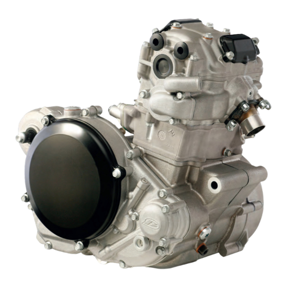
Summary of Contents for Beta REV 4T 2008
-
Page 4: Table Of Contents
INDEX INTRODUCTION CHAPTER 4 ....................... ASSEMBLY 4.1.RIGHT-HAND.CRANKCASE............4.2.LEFT-HAND.CRANKCASE............4.3.CLUTCH.CASING..................CHAPTER 1 4.4.GEARBOX.AND.SHIFTING.MECHANISM....LUBRICATION CIRCUIT . 4.4.1 Mainshaft....................4.4.2 Layshaft....................1.LUBRICATION.CIRCUIT................1.1.ENGINE.OIL. 4.5.CRANK.ASSEMBLY..................................... 1.2.CHECKING.THE.ENGINE.OIL.LEVEL. 4.6.CLOSING.THE.CRANKCASE. . -
Page 6: Introduction
INTRODUCTION FOREWORD This publication is addressed to the user of the motorcycle and to technical assistance staff. It has been written with the objective of making known, and comprehensible, the opera- tions involved in the inspection, maintenance and repair of the motorcycle it deals with. N.B. - Page 7 INTRODUCTION Petrol • Petrol is highly flammable and in certain conditions can cause explosions. • Keep heat sources, sparks and flames well away from the work area. • Always work in a well-ventilated area. • Never use petrol as a cleaning solvent. In general, avoid handling it if not strictly neces- sary.
- Page 8 INTRODUCTION • In case of exposure to high concentrations of fumes, take the affected person into an unpolluted environment and if necessary call a doctor. • Do not remove the radiator filler cap when the engine is still hot. The coolant, being under pressure, can spurt out violently and cause burns.
- Page 9 INTRODUCTION Assembly Component Thread lock Torque (Nm) Valvegear group Valve adjuster covers Bolt M6x16 Camshaft sprocket Screw M6x10 Water pump cover Screw M6x20 Carburettor flange Bolt M6x16 Exhaust flange Screw M6x15 Movable guide Bolt M6x12 Camchain tensioner Bolt M6x16 Water circuit bleed screw Screw M6x12 Water circuit drain screw Screw M6x12...
- Page 10 INTRODUCTION Assembly Component Thread lock Torque (Nm) Pivot, oil pump idler gear Screw, shallow, M6x25 Intake filter cover, output oil pump M20x1.5 Intake filter cover, scavenge oil pump M20x1.5 Filter cover, output oil pump Screw M6x20 Oil pressure relief valve Special bolt M12x1.25 Clutch group Pressure plate...
-
Page 11: Lubrication Circuit
LUBRICATION CIRCUIT 1 LUBRICATION CIRCUIT The output oil pump (1) draws in oil from the area at the base of the gearbox through its own mesh oil filter (2) and then sends it to the paper oil fil- ter (3). From here the oil, starting from the bypass valve (4), is directed in three different directions: by means of a jet (5) it lubricates the piston pin and takes heat from the crown of the piston;... -
Page 12: Checking.the.engine.oil.level
LUBRICATION CIRCUIT 1.2 CHECKING THE ENGINE OIL LEVEL The engine oil level must be checked when the en- gine is warm. Run the engine for several minutes and then switch it off. Place the bike on a flat sur- face in such a way that it is perfectly vertical. Wait a few minutes and then check the oil level in the sightglass located in the clutch casing (right- hand side of the engine). - Page 13 LUBRICATION CIRCUIT Unscrew the plug in the left-hand casing and use pliers to extract the filter. Clean it carefully and blow it through with compressed air. Check for damage to the O-rings, and replace them if necessary. Refit all the parts and tighten the plug to 15 Nm. Carry out the same procedure for the output mesh filter, for which the access is via the right-hand en- gine casing.
- Page 14 LUBRICATION CIRCUIT Position a container under the bike, near the cover for the paper filter, and unscrew the bolts on the filter cover. Then extract the paper filter using pliers. Check the condition of the O-ring too, and replace it if neces- sary.
-
Page 15: Engine Removal And Refitting
ENGINE REMOVAL AND REFITTING 2 ENGINE REMOVAL AND REFITTING 2.1 ENGINE REMOVAL Thoroughly clean the entire motorcycle and put it on a stable stand. Remove the rear mudguard. Unhook the two springs in front of the cylinder head (A). Next, remove the exhaust manifold(B) by pulling it forwards. - Page 16 ENGINE REMOVAL AND REFITTING Disconnect all the electrical cables located between the headstock and the fuel tank under the plastic tank cover: 1A connector, control unit to generator cable group 1B control unit connector 2A connector, regulator to wiring harness (regulated voltage) 2B regulator connector (regulated voltage) 3A connector, regulator to flywheel (alternating cur-...
- Page 17 ENGINE REMOVAL AND REFITTING Disconnect from the electric tap (A) the electrical connector and the fuel pipe located on the inner side of the bike, after closing the tap itself (lever in position C) Disconnect the oil vapour breather pipe. betamotor.com...
- Page 18 ENGINE REMOVAL AND REFITTING Loosen the clamp which secures the carburettor to the rubber carburettor flange. Loosen the clamp (A) which secures the rubber sleeve to the filter box and pull the carburettor backwards (see the arrow in the illustration) until the carburettor is completely disconnected from the rubber flange.
- Page 19 ENGINE REMOVAL AND REFITTING Position a drain pan under the engine and unscrew the drain bolt for the cooling system (A). Then open the radiator cap (B) to allow all the liquid in the system to flow out. Loosen the clamps that secure the cooling system pipes respectively to the cylinder (A) and the water pump (B).
- Page 20 ENGINE REMOVAL AND REFITTING Loosen the clamps that secure the cooling system pipes respectively to the cylinder (A) and the water pump (B). Unscrew the bolts that secure the stay to the frame (A) and take out the front engine mounting bolt (B) after unscrewing it.
- Page 21 ENGINE REMOVAL AND REFITTING Unscrew the bolt securing the radiator and then remove the entire radiator/stay assembly after dis- connecting the connectors for the electric fan and the radiator sensor. Take out the bolt securing the cylinder head to the frame.
-
Page 22: Refitting.the.engine
ENGINE REMOVAL AND REFITTING Remove the swing-arm bolt (A) and pull the swing- arm backwards. Take out the lower engine mounting bolt (B) and then lift the engine from the frame. 2.2 REFITTING THE ENGINE To refit the engine, follow the engine removal steps in reverse. -
Page 23: Dismantling
DISMANTLING Before you start to dismantle the engine it is essen- tial that you also read the next chapter, which deals with assembly, because it discusses all the checks that need to be carried out on individual compo- nents. 3.1 DRAINING THE OIL Remove the oil drainplug and let the oil flow out into a drain pan. -
Page 24: Ignition
DISMANTLING 3.2 IGNITION Undo the 7 bolts retaining the flywheel cover and remove it, together with the stator and pickup that are mounted on it. 3.3 CYLINDER HEAD Remove the washer from the TDC bolt and look for TDC between the compression and combustion strokes. - Page 25 DISMANTLING Remove the valve covers and then take out all the bolts securing the cylinder head cover: 2 M6x25 bolts (A), 4 M6x55 bolts (B) and 4 M6x35 bolts (C). Remove the head cover and then the camshaft end plug. If this operation is difficult, it should be carried out with the aid of a rubber hammer by tapping on the fins on the left-hand side of the engine to help in detaching the cover from the head.
- Page 26 DISMANTLING Remove the camchain tensioner by unscrewing the two retaining bolts. Remove the camshaft and its bearings from the head, taking care not to let the camchain fall into the timing case. For camshaft inspection and dis- mantling, refer to what is said in the chapter on as- sembly.
-
Page 27: Cylinder
DISMANTLING 3.4 CYLINDER Slide the cylinder up until the piston pin is visible. Then remove the retaining circlip and extract the piston pin as far as is necessary to release the con- necting rod. In this way, you can take off the cylinder and pis- ton together without having to split them. -
Page 28: Oil.pump.(Left-Hand.crankcase)
DISMANTLING 3.6 OIL PUMP (LEFT-HAND CRANKCASE) Remove the left-hand oil pump cover (2) after first _unscrewing the retaining screws (1). Next, extract the pump outer rotor (4) using a pair of circlip pli- ers, after you have removed the pin (3). Then re- move the inner rotor (5) and the O-ring (6) which seals the cover. -
Page 29: Clutch
DISMANTLING 3.7 CLUTCH Unscrew the bolts retaining the clutch cover (1) and the oil filter cover (2) and remove the two covers and their O-rings. Then unscrew the bolts holding the clutch casing (3) after you have removed the kickstart lever. Unscrew the bolts (1) retaining the clutch springs (3) in diagonal sequence to prevent the friction plates (8) from jamming when the springs are re-... - Page 30 DISMANTLING Then extract, in sequence, the special washers (2), the springs (3) and the clutch pressure plate (4). Next, remove the friction plates (8) and then the pressure plate lifter (7), the needle roller bearing (6) and the corresponding washer (5). Using a screwdriver, release the tabs on the tabwasher (10).
-
Page 31: Primary.transmission
DISMANTLING Which locks the retaining nut (9) for the clutch hub (11) and unscrew the nut, using the special tool for locking the clutch centre. Extract the clutch centre (11), the thrust washer (12), the clutch basket (13), the bush (14) and the thrust washer (15). -
Page 32: Kickstart
DISMANTLING 3.9 KICKSTART Extract the kickstart shaft complete (1) together with the thrust washer (2), ensuring that the assem- bly does not come apart accidentally. N.B. Take care when extracting the kickstart return spring from its housing. Because it is under preload, it can cause injury as a result of rapidly springing back to its rest position. -
Page 33: Oil.pump.(Right-Hand.crankcase)
DISMANTLING Take out the gearchange shaft (1), pushing back the movable pawl with a screwdriver to prevent it from interfering with the gearchange detent cam. Pull off the idler gear (5) together with its thrust washer (4), after you have first removed the retain- ing circlip (3). -
Page 34: Timing.sprocket
DISMANTLING 3.12 TIMING SPROCKET After removing the camchain, take out the movable guide (3) by unscrewing the retaining bolt (4). Threadlocker Blue Use an engineering chisel to remove the woodruff key (2) from its housing in the clutch side crank- shaft end, and then extract the timing gear (1). -
Page 35: Gearbox.and.shifting.mechanism
DISMANTLING Once you have removed the gasket from the cylinder base, use the special tool for splitting the crankcase, securing it to the left-hand crankcase half using the threads for the flywheel cover retaining bolts. Turn the engine so that the right-hand crankcase half is facing downwards. -
Page 36: Crankshaft
DISMANTLING Remove the selector forks (3) and then extract the mainshaft and layshaft as a unit, complete with all the gears. 3.15 CRANKSHAFT Attach the pad (A) (supplied with the crankcase splitter) to the crankshaft end on the clutch side, so that the crankshaft extractor (which is the same tool as the crankcase splitter) has a flat surface to push against. -
Page 37: Assembly
ASSEMBLY 4.1 RIGHT-HAND CRANKCASE Heat the crankcase in an oven to 150c°. Fit the ball bearings into their housings (main bearing 1, main- shaft bearing 2, layshaft bearing 3, gear selector drum bearing 4), and drive them home with a press and suitable mandrels, taking care that the crank- case is resting on a flat surface throughout. - Page 38 ASSEMBLY Fit the oil expansion plug (10), driving it home with a suitable pin punch, after having checked that the oilways are not blocked by blowing them through with compressed air. Threadlocker Blue Make sure that the oil pump housing is free from scoring and signs of seizure.
-
Page 39: Left-Hand.crankcase
ASSEMBLY 4.2 LEFT-HAND CRANKCASE Fit the bearings (main bearing 1, mainshaft bearing 2, layshaft bearing 3, gearchange shaft needle roller bearing 4), following the same procedure as for the right-hand crankcase. N.B. When fitting the main bearing, use a pad on the opposite side to avoid putting excessive stress on the flat surface of the housing under the load from the press. -
Page 40: Clutch.casing
ASSEMBLY Make sure that the oil pump housing is free from scoring and signs of seizure. Blow compressed air through all the oilways to clean them, and check that there are no obstructions. N.B. Before refitting the bearings, check the state of wear of the revolving parts and make sure that the balls run correctly in their tracks in the bearing. - Page 41 ASSEMBLY Fit the crankshaft oilseal (2) in its housing, with the open side facing inwards. Remember to grease the outer surface to facilitate seating. Then secure the oilseal with its retaining plate and tighten the screws to a torque of 3 Nm, after applying medium- strength thread lock.
-
Page 42: Gearbox.and.shifting.mechanism
ASSEMBLY 4.4 GEARBOX AND SHIFTING MECHANISM Before proceeding to the reassembly of the gear- box mainshaft and layshaft, carry out the following inspections: - Check the wear on the sliding surfaces of the mainshaft and layshaft. - Check that the teeth of the gears do not show signs of pitting or particular wear (A). -
Page 43: Layshaft
ASSEMBLY 4.4.2 layshaft Position the shaft (1) with the splined end facing downwards after fitting the 20x27x1 washer (2) and the spacer (3), securing them so that they can- not fall off while the other parts are being fitted. Then fit the parts from above in the following or- der: - Sliding 4th gear (4), with the dogs facing upwards, and 22.2x29x1 thrust washer (5). - Page 44 ASSEMBLY Fit the complete selector forks into the gearbox, po- sitioning them in their guides in the gears. Check the wear on the guides in the selector drum. Locate the drum in its bearing and locate the pegs in the guides. Push the two pins through the forks, taking care to use the longer one for the forks on the secondary shaft.
-
Page 45: Crank.assembly
ASSEMBLY 4.5 CRANK ASSEMBLY If the crankshaft has been dismantled for the pur- pose of replacing the connecting rod or inspecting the state of wear of the roller cage and the crankpin, be careful during subsequent reassembly that the oilway holes in the crankpin (A) and in the clutch side crankshaft half (B) are properly lined up. -
Page 46: Closing.the.crankcase
ASSEMBLY 4.6 CLOSING THE CRANKCASE Heat the main bearing in the right-hand crankcase half so as to facilitate insertion of the crankshaft. Insert the dowels in the housings provided (A). Grease the area of the crankshaft which needs to slide into the oilseal in the left-hand crankcase (1), and fit the crankcase centre gasket, cutting it in the cylinder area (2) to avoid interference with the con- necting rod during assembly. -
Page 47: Shifting.mechanism
ASSEMBLY Rotate the mainshaft and the layshaft by hand to verify that the gearbox moves correctly and that all the gearbox components slide freely. N.B. Check that the gearbox layshaft oilseal is cor- rectly positioned after the crankcase is closed up. Insert the bolts in the positions shown in the draw- ing and tighten them to 10 Nm. - Page 48 ASSEMBLY After you have fitted the gearchange shaft, check the axial play between the two pawls, which must be between 0.50mm and 0.70mm. If this clearance is exceeded, replace the movable pawl. Position the spring (1) and the detent lever (2) in their housing and hold them in place with the idler pivot pin (3).
-
Page 49: Timing.sprocket
ASSEMBLY Fit the shifting shaft into its roller bearings after oiling it well, and push back the movable pawl so that it can take up its correct position against the detent cam, and so that the gearchange shaft goes fully home. Before assembling these parts, fit the 14x30x1 thrust washer onto the shaft. -
Page 50: Oil.pumps
ASSEMBLY 4.9 OIL PUMPS N.B. The pumps have reference marks both on the outer rotor (A) and on the inner rotor (B). During as- sembly these two marks must remain on the same side of the pump and must always face towards the inside of the pump housing. - Page 51 ASSEMBLY Measure the clearance between the outer rotor and the pump housing, using a feeler gauge for this too. Standard clearance 0.09-0.23mm. Measure the axial clearance, defined as the differ- ence between the depth of the pump housing in the crankcase and the thickness of the outer rotor. Standard clearance 0.05-0.10mm.
- Page 52 ASSEMBLY Insert the two filters (17) into their holes, after first lubricating them with oil and fitting the O-rings (18). N.B. The two filters have a tapering internal cavity. Use a pin punch with a taper point to facilitate fit- ting.
-
Page 53: Kickstart
ASSEMBLY Threadlocker Blue 4.10 KICKSTART 4.10.1 Preassembly of kickstart shaft Clamp the kickstart shaft (2) with the serrated end facing downwards and fit the kickstart sleeve (3) from above, applying molycote grease to the splined section. Fit the spring (4) and the 20x30x0.5 thrust washer (5), securing them with the circlip (6). -
Page 54: Assembling The Kickstart
ASSEMBLY 4.10.2 assembling the kickstart Insert the kickstart shaft (1) into its housing after first oiling it well and fitting the 16x25x0.5 thrust washer (13) onto it, taking care that the spring is secured in the hole provided for it (B). N.B. -
Page 55: Clutch
ASSEMBLY Fit the idler gear (1) on its pivot pin with the con- cave side facing outwards, fit the special 11x17x0.5 washer (2), and secure with the circlip (3). Fit the primary transmission gear (4) with the convex side facing inwards, taking care to align the keyway with the woodruff key itself. - Page 56 ASSEMBLY Check the wear on the teeth (A) of the clutch centre which engage with the driven plates. Fit the clutch hub (5) and secure it with the nut (7) after you have fitted the tabwasher (6). Lock the clutch hub with the special tool and tight- en the nut to 90 Nm.
- Page 57 ASSEMBLY After you have fitted all the friction plates, fit the pressure plate lifter (10) in the central hole in the clutch basket, together with the lifter needle roller bearing (11) and the corresponding washer (12). Check the wear on the needle roller bearing and the contact surfaces.
-
Page 58: Flywheel
ASSEMBLY 4.13 FLYWHEEL Carefully degrease the taper on the crankshaft be- fore proceeding to fit the flywheel. Insert the drive key (1) in the keyway machined for it in the left-hand crankshaft journal, using a rubber hammer if necessary. Fit the flywheel (2) and secure it with the flanged nut (3), tightening to a torque of 120 Nm. -
Page 59: Piston.and.cylinder
ASSEMBLY 4.14 PISTON AND CYLINDER 4.14.1 measurements and checks 4.14.1.1 Cylinder Check whether the lower and upper surfaces of the cylinder show deformation. Use a surface plate and a dial gauge to measure for flatness. The limit value for deformation is 0.05mm. Recondition the cylinder in the event of out-of-lim- its values. - Page 60 ASSEMBLY Fit the piston ring into the cylinder and use a feeler gauge to measure the gap between the two ends of the ring. When inserting the ring into the bore, use the top of the piston to ensure that the ring is sitting parallel to its working plane, and position it approxi- mately 10mm from the top surface of the cylinder.
-
Page 61: Fitting
ASSEMBLY Measure the internal diameter of the conrod small end and then determine the play with the piston pin. If this value exceeds the limit, with the diameter of the piston pin within limits, replace the connect- ing rod. limit of play 0.07mm 4.14.2 fitting 4.14.2.1 Studs Insert the two dowel pins (1) into the right-hand... -
Page 62: Cylinder
ASSEMBLY 4.14.2.3 Cylinder Fit the M6x12 bolt (1) for draining the cooling wa- ter, with the corresponding washer 6x12x1. Tighten the bolt to 8 Nm. Insert the piston into the cylinder from below, po- sitioning it in the correct direction (with the arrow pointing in the bike’s direction of travel). -
Page 63: Cylinder.head.cover
ASSEMBLY camchain passes freely through the timing case on the right-hand side of the engine. Insert the two dowels (1) and the movable cam- chain guide (2). Fit the cylinder head gasket, taking care that it does not obstruct the oilway (3). 4.15 CYLINDER HEAD COVER Before proceeding to fit the head cover, carry out the following checks:... -
Page 64: Cylinder.head
ASSEMBLY Fit the inlet rocker (2) and the exhaust rocker (3) as indicated in the photo, inserting the 12x17x0.5 thrust washers (7) between the rockers and the head cover, after you have lubricated them well with engine oil. Insert the rocker spindles (8) with the cutouts (A) adjacent to the straight-through holes (B) for the cylinder-head hold-down bolts, and with the end containing a threaded hole facing outwards. - Page 65 ASSEMBLY the seat. Then insert the valve into the guide until it is pressing against the seat, and rotate it on its axis. When the valve is removed, the dye will be missing on the contact area. The width of this contact area must fall within certain limits: Standard 1.15-1.40mm Service limit 1.80mm...
-
Page 66: Fitting
ASSEMBLY 4.16.2 fitting Insert the oil plug (1) using a pin punch. Fit the lower spring caps (2) and then the valve guide oilseals (3). Take care not to confuse the low- er spring caps with the upper ones. The upper caps differ from the lower ones in that they have a more marked bevel on the opposite side to the spring. -
Page 67: Valvegear
ASSEMBLY Apply a few taps to the upper spring caps with a double rubber hammer to help the split collets to settle. Fit the two roller bearings (10, 11) for the water pump shaft into their housings in the head. The smaller-diameter bearing (10) should be driven fully home in its housing. -
Page 68: Fitting The Valvegear
ASSEMBLY Fit the decompressor weight (4) and the relative spring (5). The spring must be preloaded by half a turn when fitted. Then check that the decompressor mass returns automatically to its initial position af- ter being displaced. If this does not happen, replace the spring. - Page 69 ASSEMBLY Pass the camchain around the camshaft sprocket, and fit onto the camshaft first the sealed bearing (8) and then the bearing on the chain side (9). Take care to time up the camshaft properly. The crankshaft is locked at TDC by the special bolt which was fitted earlier (see 4.11).
- Page 70 ASSEMBLY Seal the holes in the head cover for the rocker spin- dles with the appropriate gaskets (18) and plugs (19). Adjust the valve clearances, inserting a feeler gauge between the adjuster and the top of the valve, and using the adjuster screw to regulate the play. inlet clearance 0.10mm.
-
Page 71: Clutch.casing
ASSEMBLY Check that the tensioner plunger (A) moves freely, and check the teeth (B) on the plunger for wear. Before fitting, push the plunger all the way into the tensioner body. Fit the tensioner body and its gasket, retaining it with M6x16 bolts tightened to 8 Nm. - Page 72 ASSEMBLY Grease the areas adjacent to the threaded holes so as to help the clutch casing gasket (1) to adhere, and thus to prevent it from becoming detached the next time the cover is opened. Fit the clutch casing (2) with its retaining bolts, tightening them to 10 Nm.
-
Page 73: Ignition
ASSEMBLY 4.19 IGNITION Insert the two dowels (1) into the left-hand crank- case and apply some grease in the area of the threaded holes in order to help the flywheel cover gasket (8) to adhere. N.B. Before you apply the gasket, cut off the excess section as shown in the picture above. -
Page 74: Final.details
ASSEMBLY Fit the flywheel cover to the left-hand crankcase half and retain it with the bolts indicated in the picture above. Tighten the bolts to 10 Nm. N.B. Do not tighten the two M6x35 screws at this stage, as they will also be used to retain the sprocket cover which will be fitted only after the chain has been passed around the sprocket, once the motorcy- cle is assembled. - Page 75 ASSEMBLY Fit the exhaust flange (12) with four M6x15 screws (14) tightened to 10 Nm. Under the heads of the screws fit the two plates (13) for anchoring the ex- haust collector support springs. These plates are fit- ted to the top right and bottom left bolts, looking at the engine from the front (exhaust side).
Need help?
Do you have a question about the REV 4T 2008 and is the answer not in the manual?
Questions and answers