Table of Contents
Advertisement
Quick Links
HUSSONG MANUFACTURING CO., INC.
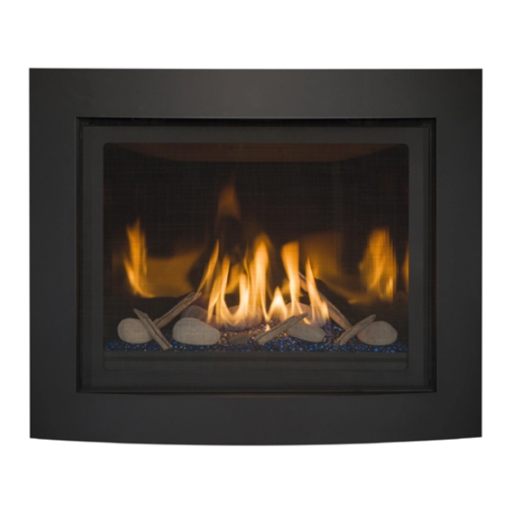
DELANO-36S
Model #DEL-36S
Direct Vent Gas Fireplace
WARNING:
FIRE OR EXPLOSION HAZARD
Failure to follow safety warnings exactly
could result in serious injury, death, or
property damage.
ͷ Do not store or use gasoline or other
flammable vapors and liquids in the
vicinity of this or any other appliance.
ͷ WHAT TO DO IF YOU SMELL GAS
• Do not try to light any appliance.
• Do not touch any electrical switch; do
not use any phone in your building.
• Leave the building immediately.
• Immediately call your gas supplier from
a neighbor's phone. Follow the gas
supplier's instructions.
• If you cannot reach your gas supplier,
call the fire department.
ͷ Installation and service must be performed
by a qualified installer, service agency or
the gas supplier.
This
appliance
an
aftermarket,
manufactured home (USA only) or mobile
home, where not prohibited by local codes.
This appliance is only for use with the type
of gas indicated on the rating plate. This
appliance is not convertible for use with
other gases, unless a certified kit is used.
Hussong Mfg. Co., Inc. • DEL-36S
may
be
installed
permanently
located,
INSTALLER: Leave this manual with the appliance.
CONSUMER: Retain this manual for future reference.
Tested &
Listed By
C
OMNI-Test Laboratories, Inc.
DANGER
A barrier designed to reduce the risk of burns
from the hot viewing glass is provided with this
appliance and shall be installed for the protection
of children and other at-risk individuals.
in
English
and
available through your local dealer. Visit our website
www.kozyheat.com or scan the QR code for our mobile app.
Les manuels d'installation en français et en anglais sont
disponibles chez votre détaillant local. Visitez www.kozyheat.
com ou scannez ce code QR pour notre application mobile.
Report No: 0216GF014S • Rev. 03, January 2016
Installation and
Operation Manual
Portland
Oregon USA
US
HOT GLASS WILL
CAUSE BURNS
DO NOT TOUCH GLASS
UNTIL COOLED
NEVER ALLOW CHILDREN
TO TOUCH GLASS
French
installation
manuals
are
Advertisement
Table of Contents

Related Manuals for kozy heat DELANO-36S


Summary of Contents for kozy heat DELANO-36S
- Page 1 Installation and Operation Manual HUSSONG MANUFACTURING CO., INC. DELANO-36S Model #DEL-36S Direct Vent Gas Fireplace WARNING: Tested & Portland FIRE OR EXPLOSION HAZARD Listed By Oregon USA Failure to follow safety warnings exactly OMNI-Test Laboratories, Inc. could result in serious injury, death, or property damage.
- Page 3 CONGRATULATIONS! We welcome you as a new owner of a Kozy Heat gas fireplace. Kozy Heat products are designed with superior components and materials, and assembled by trained craftsmen who take pride in their work. To ensure you receive a quality product, the burner and valve assembly are 100 percent test-fired, and the complete fireplace is thoroughly inspected before packaging.
-
Page 5: Table Of Contents
TABLE OF CONTENTS TABLE OF CONTENTS ..............5 7.7 #800-1 Series Direct Vent Termination Kit(s) ......24 7.8 Horizontal Vent Heat Shield Installation ........25 1.0 INTRODUCTION ..............7 8.0 FIREPLACE SETUP ..............26 1.1 Appliance Certification ..............7 8.1 Glass Frame Assembly ..............26 1.2 Requirements for the Commonwealth of Massachusetts ..7 8.2 Light Kit ..................26 2.0 SPECIFICATIONS .............. -
Page 7: Introduction
1.0 INTRODUCTION 1.1 Appliance Certification OBSTRUCTIONS”. Laboratory: OMNI-Test Laboratories in Portland, Oregon 1.2.4 Inspection Standards: The state or local gas inspector of the side wall horizontally vented gas fueled equipment shall not approve the installation ANSI Z21.88-2014/CSA 2.33-2014, Vented Gas Fireplace Heaters unless, upon inspection, the inspector observes carbon monoxide CGA 2.17-M91 (R2009), Gas-Fired Appliances for Use at High detectors and signage installed in accordance with the provisions... -
Page 8: Specifications
2.0 SPECIFICATIONS 2.1 Appliance Components Part Number Description DEL-150 Control Board Assembly 700-203 Manual Gas Shut-off Valve DEL-135A Burner Assembly DSL-057T Glass Frame Assembly DEL-LKT Light Kit 700-408 Remote Control SL36-085 5 in (127 mm) Restrictor Plate DEL-HHS Horizontal Vent Heat Shield 2.1.1 Additional Components Required Refer to Section 7.0 Venting on page 20 for approved vent systems. -
Page 9: Appliance Dimensions
(387mm) LEFT FRONT RIGHT 10” (254mm) 42” (1067mm) 32” 24” (813mm) (609mm) ½ ” (241mm) ¼ ” ⁄ ” (32mm) (213mm) ½ ⁄ ” ¾ ” ” (140mm) (797mm) (70mm) ⁄ ” (912mm) Figure 2.1, Delano-36S Unit Dimensions SPECIFICATIONS 9... -
Page 10: Safety Barrier Dimensions
2.4 Safety Barrier Dimensions 2.4.1 Safety Barrier Installation Center the screen front over the glass frame assembly, WARNING: A barrier designed to reduce the risk of burns from allowing the screen front’s mounting brackets to fit inside the the hot viewing glass is provided with this appliance and shall air openings. -
Page 11: Framing
3.0 FRAMING 3.1 Appliance Placement STAND-OFF BRACKETS AND HEAT SHIELDS, AS SHIPPED Considerations WARNING: Due to high temperatures, the appliance should be located out of traffic and away from furniture and draperies. FIRE HAZARD: Do NOT install this appliance directly on carpeting, vinyl, or any other combustible material other than wood. -
Page 12: Clearances To Combustibles
3.3 Clearances to Combustibles Table 3.1, Minimum Appliance Clearances to Combustible Material From appliance top stand-offs 0 in 0 mm From appliance left and ride side stand-offs 0 in 0 mm From appliance back 1/4 in 6 mm From appliance top to ceiling 31 in 787 mm Appliance sides to adjacent sidewall... -
Page 13: Wall Enclosure Rough Opening
3.4 Wall Enclosure Rough Opening • If masonry is to be used (optional), prepare the necessary foundation for the masonry load. When masonry construction WARNING: Provide adequate clearances around air openings is to be used, a lintel must be used over the top of the into the combustion chamber. -
Page 14: Floor Support And Protection
• Kozy Heat #800-1 series flexible vent system and rigid vent systems require a minimum of 3 in (76 mm) from the top surface of horizontal pipe, and 1 in (25 mm) from the sides and bottom surfaces of horizontal pipe. -
Page 15: Facing And Finishing
4.0 FACING AND FINISHING 4.1 Nailing Flange Assembly SIDE VIEW and Installation NOTE: Depending on facing material, tabs can be adjusted forward or backward up to ½ in (13 mm). CAUTION: Never permanently remove these assemblies from the fireplace—they must be secured regardless of finish material used. -
Page 16: Mantel Requirements
4.2 Mantel Requirements NON-COMBUSTIBLE ZONE 14” (356mm) ½ ” (344mm) 4” (102mm) 22” ¾ ” (559mm) (19mm) 16” (406mm) 10” (254mm) ½ ” (13mm) NON-COMBUSTIBLE MATERIAL ONLY SIDEWALL CLEARANCE Figure 4.2, Mantel, Trim and Sidewall Requirements 16 FACING AND FINISHING... -
Page 17: Gas Line Connection
5.0 GAS LINE CONNECTION 5.1 Gas Conversion (sold separately) ATTENTION: The conversion shall be carried out in accordance with the requirements of the provincial authorities having jurisdiction and in accordance with the requirements of the ANSI Z223.1 installation code. This fireplace is manufactured for use with natural gas. Follow the instructions included with the conversion kit if converting to LP gas. -
Page 18: Termination Locations
6.0 TERMINATION LOCATIONS 6.1 Vertical Vent Cap Termination WARNING: This appliance must not share or be connected to a chimney flue serving a separate solid-fuel burning appliance. LOWEST DISCHARGE OPENING APPROVED CAP MINIMUM *12” (.30m) APPROVED VENT PIPE ROOF PITCH = x/12 H - MINIMUM HEIGHT FROM ROOF TO LOWEST DISCHARGE OPENING *If vent is closer than 12 in (.30 m), it must terminate at least 2... -
Page 19: Minimum Termination Clearances
6.2 Minimum Termination Clearances AREA WHERE TERMINAL IS NOT PERMITTED Figure 6.2, Vent Cap Locations Canadian installations US installations Clearance above grade, veranda, porch, deck, or balcony 12 in (30 cm) 12 in (30 cm) Clearance to window or door that may be opened 12 in (30 cm) 9 in (23 cm) Clearance to permanently closed window (recommended to prevent condensation... -
Page 20: Venting
NOTE: If using a vent 4” x 6-5/8” Decreaser, follow the vent pipe manufacturer’s wall thimble installation instructions. Vent Manufacturer Direct Vent System Termination Kozy Heat’s #800-WPT series, or wall thimble products that American Metal Ameri-Vent Horizontal & Vertical comply with the required 3 in (76 mm) top clearance to Products combustibles, must be installed for all horizontal 5”... -
Page 21: Vertical Terminations
7.5 Vertical Terminations VENTING DIAGRAM (VERTICAL TERMINATIONS) NOTE: Attic insulation shields may be insulated using unfaced (A) Stand-off Brackets (D) Vent Heat Shield (not applicable) (B) Stand-off Heat Shields (E) 4” x 6 ” Reducer insulation products listed as non-combustible per ASTM E 136. (C) 90°... -
Page 22: Combination Venting
7.6 Combination Venting VENTING DIAGRAM (5” x 8” HORIZONTAL TERMINATIONS) (A) Stand-off Brackets (D) Vent Heat Shield 7.6.1 5” x 8” Vent Configurations (B) Stand-off Heat Shields (E) 4” x 6 ” Reducer (not applicable) (C) 90° Elbow (F) Termination Cap IMPORTANT: The horizontal vent heat shield must be installed when incorporating minimum horizontal venting. - Page 23 7.6.2 4” x 65/8” Reducer Vent Configurations VENTING DIAGRAM (4” x 65/8” REDUCER HORIZONTAL TERMINATIONS) IMPORTANT: Horizontal vent sections require ¼ in (6 mm) rise (A) Stand-off Brackets (D) Vent Heat Shield (not applicable) for every 12 in (305 mm) of travel. (B) Stand-off Heat Shields (E) 4”...
-
Page 24: 800-1 Series Direct Vent Termination Kit(S)
7.7 #800-1 Series Direct Vent insulation products listed as non-combustible per ASTM E 136. Termination Kit(s) Apply a liberal bead of exterior sealant around outer edge of IMPORTANT: The horizontal vent heat shield must be installed termination box (A), placing assembly through the wall-pass when incorporating minimum horizontal venting. -
Page 25: Horizontal Vent Heat Shield Installation
7.8 Horizontal Vent Heat Shield Installation IMPORTANT: The horizontal vent heat shield must be installed when incorporating minimum horizontal venting. Loosen, but do not remove the (3) attachment screws in front of the flue collar on the top of the fireplace. Bend the heat shield at perforation to a 90°... -
Page 26: Fireplace Setup
8.0 FIREPLACE SETUP 8.1 Glass Frame Assembly 8.3 Glass Media Installation WARNING: Do not operate this fireplace with the glass removed, WARNING: DO NOT BLOCK PILOT WITH GLASS MEDIA. A cracked, or broken. Replacement of the glass assembly, should BLOCKED PILOT MAY CAUSE DELAYED IGNITION. be done by a licensed or qualified service person. -
Page 27: Ncl-028 Optional Fan Kit
8.4 #NCL-028 Optional Fan Kit WARNING - Electrical Grounding Instructions: This appliance is equipped with a three-prong (grounding) plug for your protection against shock hazard and should be plugged directly into a properly grounded three-prong receptacle. Do not cut or remove the grounding prong from this plug. -
Page 28: Control Board Removal And Installation
8.5 Control Board Removal and Installation WARNING: If burner and/or pilot have been burning, use appropriate protection to avoid burns or damage to personal property before removing any components. DO NOT OPERATE THIS APPLIANCE WITHOUT THE SEALING GASKET (LOCATED UNDER THE CONTROL BOARD) IN PLACE. IF GASKETING IS DAMAGED, IT MUST BE REPLACED. -
Page 29: Electrical Information
9.0 ELECTRICAL INFORMATION 9.2 Wiring Requirements WARNING: Do not use this fireplace if any part has been under water. Immediately call a qualified service technician to inspect • The IFC System Module requires 120V of electricity and/or this appliance and to replace any part of the control system and batteries to operate. -
Page 30: Operating Instructions
10.0 OPERATING INSTRUCTIONS FOR YOUR SAFETY READ BEFORE OPERATING WARNING: If you do not follow these instructions exactly, a fire or explosion may result causing property damage, personal injury, or loss of life. This appliance is equipped with an ignition device which phone. -
Page 31: Setup Proflame
10.1 Setup Proflame 2 IFC Module • Turn the main burner OFF by setting the ON/OFF switch in the OFF position. The pilot will remain lit even if burner is turned Set the main ON/OFF rocker switch in the OFF position. off, provided CPI mode is turned on. -
Page 32: Ifc Module Ignition Sequence
10.6 IFC Module Ignition Sequence The IFC module will try (2) times for ignition, each lasting approximately (60) seconds, with approximately (35) seconds between each attempt. With the system in OFF position, press the remote control ON/OFF key. Approximately (4) seconds after this key is depressed, the IFC module will generate sparks to the pilot hood. -
Page 33: Remote Control Operation
PROFLAME 2 TRANSMITTER LCD DISPLAY KEY LOCK TRANSMISSION LOW BATTERY ALARM THERMOSTAT OFF/ON/SMART ROOM BLUE BACK TEMPERATURE LCD DISPLAY CPI MODE SET POINT TEMPERATURE/LEVEL/STATE FLAME ON ON/OFF KEY THERMOSTAT KEY LIGHT ON UP/DOWN ARROWS MODE KEY 10.8 Remote Control Operation 10.8.3 Pilot Ignition Selection (IPI/CPI) This system has the option of a continuous (standing) pilot. -
Page 34: Smart Thermostat
10.8.4 Turn ON the Appliance ROOM TEMPERATURE With the system in the OFF position, press the remote control ON/OFF key to turn ON the appliance. A single ‘beep’ will emit from the IFC module to confirm reception of the command. The LCD screen will display all active icons, and the IFC module will start the ignition sequence. -
Page 35: Fan Speed Control
10.8.8 Fan Speed Control Fan speed can be adjusted through (6) speeds. To activate this function, Press the mode key to index to the fan control icon. Press the up or down arrow keys to turn on, off, or to adjust fan speed. -
Page 36: Adjustment
11.0 ADJUSTMENT 11.1 Pressure Testing 11.1.2 Manifold Pressure Test Light pilot. NOTE: The appliance and its appliance main gas valve must be disconnected from the gas supply piping system during any Loosen manifold (OUT) pressure tap by turning screw pressure testing of the system at test pressures in excess of ½ counter-clockwise. -
Page 37: Burner Flame Adjustments
11.2 Burner Flame Adjustments IMPORTANT: Slight adjustments to the venturi opening will create dramatic results. Adjust at slight increments until desired WARNING: To avoid property damage or personal injury, allow look is achieved. Always burn the fireplace insert for at least 15 the fireplace ample time to cool before making any adjustments. -
Page 38: Restrictor Installation
11.2.2 Restrictor WARNING: To avoid property damage or personal injury, allow the fireplace ample time to cool before making any adjustments. RESTRICTOR PLATE REMOVE CIRCLE TO CREATE LESS RESTRICTON WARNING: Improper vent installation may cause the burner flames to lift or “ghost.” Perform a visual check on flame appearance after restrictor adjustment to ensure proper performance. -
Page 39: Troubleshooting
12.0 TROUBLESHOOTING ATTENTION: Troubleshooting must be performed by a qualified • Verify all connections between the wire harnesses and the technician. system components are proper and positive. Before proceeding with the steps in the following troubleshooting • Verify the communication link is established between the guide, remote control and the IFC module. - Page 40 Issue Cause Solution Pilot and burner No LP (propane) gas in tank Check LP (propane) tank. Refill if necessary. extinguish while in Incorrect glass assembly Refer to Section 8.1 Glass Frame Assembly on page 26. operation installation Incorrect vent cap installation Adjust if necessary.
-
Page 41: Maintenance
13.0 MAINTENANCE 13.2 Fans ATTENTION: Installation and repair should only done by a qualified service person. The appliance should be inspected CAUTION: Label all wires prior to disconnection when servicing before use and at least annually by a professional service controls. -
Page 42: Replacement Parts List
14.0 REPLACEMENT PARTS LIST Replacement parts are available through your local dealer. Contact your local dealer for availability and pricing. CONTROL BOARD AND PARTS Control Board - NG DEL-150 Valve Step Motor - NG 700-504 Control Board - LPG DEL-151 Valve Step Motor - LPG 700-504-1 S.I.T. -
Page 43: Limited Warranty
Hussong Manufacturing Co., Inc. warranties to the original all times, according to the operating instructions furnished. purchaser of this Kozy Heat Fireplace, that it is free of defects in This warranty is limited to defects in material and workmanship. It materials and workmanship at the time of manufacture. -
Page 45: Lifetime Warranty
Kozy Heat Fireplace will not be defective in than those incurred by Hussong Manufacturing Co., Inc. to repair material or workmanship under normal use and service for as long or replace the defective component.
Need help?
Do you have a question about the DELANO-36S and is the answer not in the manual?
Questions and answers