Table of Contents
Advertisement
Quick Links
Advertisement
Table of Contents

Related Manuals for ATEN CS428


Summary of Contents for ATEN CS428
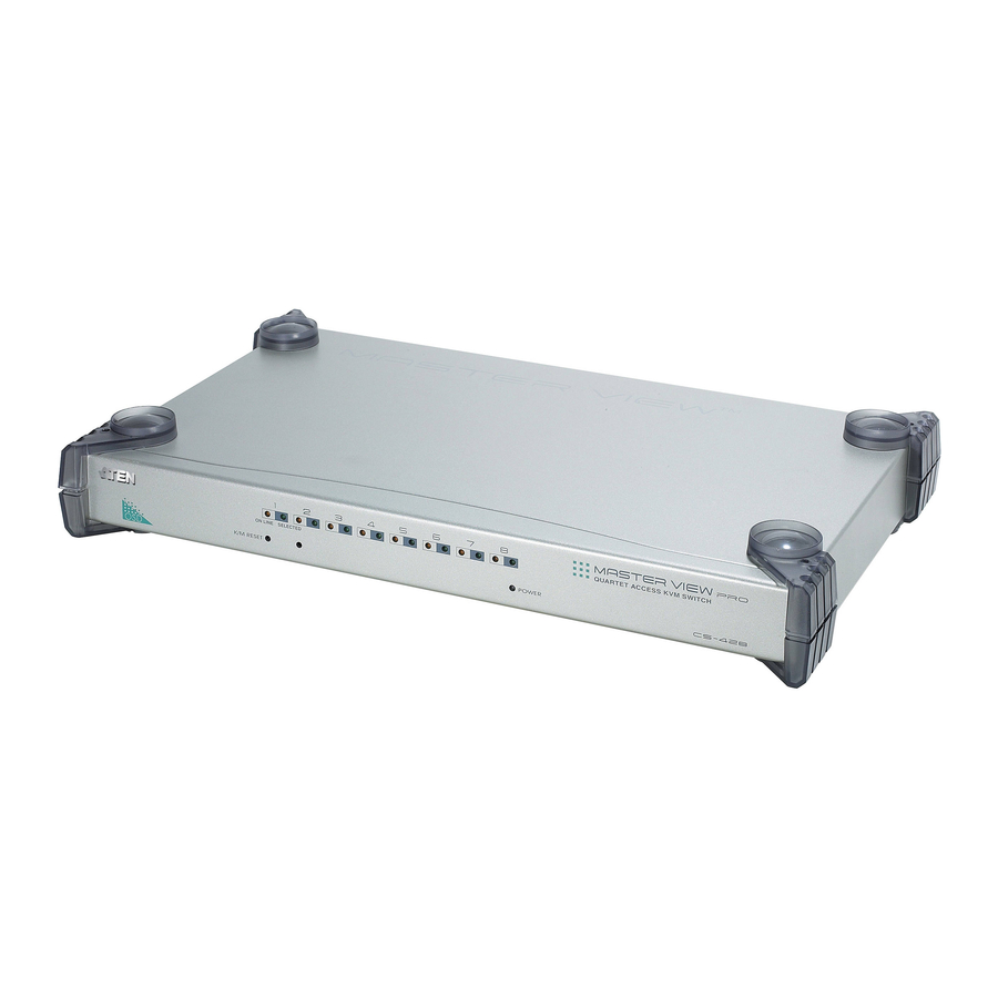
- Page 1 4 Console / 8 Port KVM Switch CS428 User Manual www.aten.com...
-
Page 2: Fcc Information
CS428 User Manual FCC Information This is an FCC Class A product. In a domestic environment this product may cause radio interference in which case the user may be required to take adequate measures. This equipment has been tested and found to comply with the limits for a Class A digital device, pursuant to Part 15 of the FCC Rules. -
Page 3: User Information
The manufacturer is not responsible for any damage incurred in the operation of this system if the correct operational voltage setting was not selected prior to operation. PLEASE VERIFY THAT THE VOLTAGE SETTING IS CORRECT BEFORE USE. CS428 User Manual... -
Page 4: Package Contents
* Features may have been added to the CS428 since this manual was printed. Please visit our website to download the most up to date version of the manual. -
Page 5: Table Of Contents
F2 EDIT: ..........17 CS428 User Manual... - Page 6 CS428 User Manual F3 LIST: ..........18 F4 SCAN: .
-
Page 7: About This Manual
It covers all aspects of installation, configuration and operation. An overview of the information found in the manual is provided below. Chapter 1, Introduction, introduces you to the CS428 system. Its purpose, features and benefits are presented, and its front and back panel components are described. -
Page 8: Conventions
CS428 User Manual Conventions This manual uses the following conventions: Monospaced Indicates text that you should key in. Indicates keys you should press. For example, [Enter] means to press the Enter key. If keys need to be chorded, they appear together in the same bracket with a plus sign between them: [Ctrl+Alt]. -
Page 9: Introduction
Chapter 1 Introduction Overview The CS-428 KVM Switch is a control unit that allows four independent keyboard, mouse, and monitor Consoles to access eight computers, either independently or on a multiuser shared basis, in a convenient, cost effective manner. A Master View CS-428 unit can control up to 8 PCs. Since it can be cascaded one level down to a CS-138A, CS-9138, CS-128A, or CS-124A, up to 9 Master View units (the CS-428 plus eight cascaded ones), can control up to 64 computers from any of the four Consoles. -
Page 10: Features
CS428 User Manual Features 4 Consoles Control 8 Computers Up to four users can operate up to 64 computers (via cascading to CS- 138A, CS-9138, CS-128A, or CS-124A) at the same time Each console has its own access control Two level password security (one Administrator; four User passwords) -
Page 11: Requirements
Requirements Console A VGA, SVGA, or Multisync monitor capable of the highest resolution that you will be using on any computer in the installation. If a monitor switches to a computer using a resolution that is higher than the resolution that the monitor can support, serious damage to the monitor may result. -
Page 12: Components
CS428 User Manual Components Front Panel Component Port LEDs The Port LEDs provide status information about their corresponding Computer Ports. There is one pair of LEDs for each Port. The one on the left is the On Line LED; the one on... -
Page 13: Rear Panel
Rear Panel Component Power Switch Console 3 and 4 Connectors Power Jack Console 2 Microphone and Speaker Jacks Console 2 KVM Connectors Console 1 Microphone and Speaker Jacks Console 1 KVM Connectors KVM Port Section Description A rocker switch to power the system on and off. Use KVM Cable sets (see Cables, page 3), to connect the components that make up Consoles 3 and 4 to these ports. - Page 14 CS428 User Manual This Page Intentionally Left Blank...
-
Page 15: Hardware Setup
Rack Mounting The CS428 can be mounted in a 1U system rack. To rack mount the unit, do the following: 1. Remove the stacking brackets by unscrewing them from the unit, as shown... -
Page 16: Single Station Installation
1. Plug the keyboard, monitor, mouse microphone and speaker cables for Consoles 1 and 2 into the console port connectors located on the CS428’s rear panel. Each port is labeled with an icon to indicate itself. Note: Use of microphone and speakers is optional. -
Page 17: Cascaded Installation
KVM ports of the CS428. The cascaded Master Views that connect back to the CS428 (referred to as the First Stage unit), are considered Second Stage units. As many as 64 computers can be controlled in a complete two stage installation. - Page 18 On function; unplug the First Stage unit). 2. Use a 2L-1601P KVM Cable set (see Cables, page 3), to connect any available KVM port on the CS428 (First Stage unit) to the Console Port connectors of the Second Stage unit.
-
Page 19: Basic Operation
2. Wait 10 seconds, then restart the CS428. Note: When the CS428 comes up it issues a long beep, and the Consoles are automatically logged out. Each Console logout produces a short beep - so you will hear one long and four short beeps. -
Page 20: Port Numbering
Note: The KVM port numbers are clearly indicated on the back panels of the switches. For example, a computer connected to KVM port 7 of a First Stage CS428, would have a PN of 7. A computer connected to a Second Stage cascaded Master View has a two digit... -
Page 21: Osd Operation
OSD Overview On Screen Display (OSD), provides a menu driven interface to handle the computer switching procedure. All operations start from the OSD Main Menu. To activate the Main Menu, tap either Ctrl key twice. Note: 1. The keys must be on the same side (both left, or both right). 2. - Page 22 CS428 User Manual When you invoke the OSD, a screen similar to the one below appears: Note: 1. The diagram depicts the Administrator's Main Screen. The User Main Screen does not show the F2 and F5 function, since they are reserved for the Administrator and can't be accessed by ordinary Users.
-
Page 23: Osd Navigation
Console. This is so, because accessing any one computer attached to a Second Stage unit ties up the entire CS428 Port that the unit is cascaded down from. Only after the original Console no longer has access - either... -
Page 24: Osd Main Menu Headings
CS428 User Manual OSD Main Menu Headings Heading This column lists the Port Numbers for all the KVM Ports. The simplest method to access a particular computer (assuming you know which port it is attached to), is to Double Click it with the Mouse; or to use the Navigation Keys to move the Highlight Bar to it, then press [Enter] . -
Page 25: F2 Edit
F2 EDIT: This is an Administrator function. To help remember which computer is attached to a particular port, every port can be given a name. The Edit function allows the Administrator to create, modify, or delete port names. To Edit a port name: 1. -
Page 26: F3 List
CS428 User Manual F3 LIST: This function lets you broaden or narrow the scope of which ports the OSD lists. This will be different for each Console, depending on the choices made for that Console. The choices and their meanings are given in the table, below:... -
Page 27: F4 Scan
F4 SCAN: Clicking the F4 field, or pressing [F4] initiates Scan Mode, in which the OSD cycles through all the ports that have been selected for scanning with the Scan Mode setting (see SCAN MODE, page 22). When you want to stop at a particular location, press the [Spacebar] to stop scanning. -
Page 28: F5 Adm
CS428 User Manual F5 ADM: F5 allows an Administrator to configure the OSD operation of the Console. To change a setting Double Click it; or use the Up and Down Arrow Keys to move the highlight bar to it then press [Enter]. - Page 29 SET MULTIUSER This function determines whether or not the same ID can be MODE used to log into the CS428 from different Consoles at the same time. 1. If Disabled, the same ID cannot be used; if Enabled (the 2. If Enabled, the F4, F6, and F7 settings set for any one 3.
-
Page 30: F6 Set
CS428 User Manual F6 Set: [F6] allows you to configure the OSD settings for the Console you are working at. To change a setting: 1. Double Click it; or move the highlight bar to it, then press [Enter] 2. Press [Esc] to activate it. - Page 31 (Continued from previous page.) Setting SCAN DURATION Determines how long the display dwells on each port when it cycles through the selected ports in Quick View Scan Mode. Key in a value from 1 - 255 seconds, then press [Enter]. Default is 3 seconds.
-
Page 32: F7 Qv
CS428 User Manual F7 QV You can broaden or narrow the number of ports that get automatically scanned by selecting only the ones you want with the QV (Quick View Scan) function. [F7] is a toggle that selects or deselects the currently highlighted port for the Quick View Scanning function (see F4, above). -
Page 33: Appendix
Safety Instructions General Read all of these instructions. Save them for future reference. Follow all warnings and instructions marked on the device. Do not place the device on any unstable surface (cart, stand, table, etc.). If the device falls, serious damage will result. Do not use the device near water. - Page 34 CS428 User Manual To help protect your system from sudden, transient increases and decreases in electrical power, use a surge suppressor, line conditioner, or un-interruptible power supply (UPS). Position system cables and power cables carefully; Be sure that nothing rests on any cables.
-
Page 35: Rack Mounting
Appendix Rack Mounting Before working on the rack, make sure that the stabilizers are secured to the rack, extended to the floor, and that the full weight of the rack rests on the floor. Install front and side stabilizers on a single rack or front stabilizers for joined multiple racks before working on the rack. -
Page 36: Technical Support
CS428 User Manual Technical Support International Email Support Online Support Technical Support Troubleshooting Documentation Software Updates Telephone Support North America Email Support Online Support Technical Support Troubleshooting Documentation Software Updates Telephone Support When you contact us, please have the following information ready beforehand: Product model number, serial number, and date of purchase. -
Page 37: Master View - Computer Connection Tables
Master View - Computer Connection Tables Switches Switches Type CS428 CS-128A / CS-138A / CS-9138 CS-128A / CS-138A / CS-9138 CS-128A / CS-138A / CS-9138 CS-128A / CS-138A / CS-9138 CS-128A / CS-138A / CS-9138 CS-128A / CS-138A / CS-9138... -
Page 38: Specifications
CS428 User Manual Specifications Function Computer Direct Connections Port Selection Connectors Console 1 & 2 Keyboard Console 3 & 4 KVM Ports Power Switches Reset LEDs On Line Selected Power Emulation Keyboard Mouse Video Power Consumption Environment Operating Temp. Storage Temp. -
Page 39: Osd Factory Default Settings
OSD Factory Default Settings Setting MULTIUSER MODE Enabled ACCESS TIMEOUT 10 Seconds OSD HOTKEY [Ctrl] [Ctrl] DISPLAY MODE The Port Number plus the Port Name DISPLAY DURATION 3 Seconds SCAN DURATION 3 Seconds Power On Self Test When you turn the unit On, it undergoes a Power On Self Test. If there is a problem, Port LEDs 1 - 4 flash repeatedly according to a pattern that indicates what the problem is: Pattern... -
Page 40: Troubleshooting
CS428 User Manual Troubleshooting Symptom Possible Cause Keyboard The connection from and/or the selected port to Mouse not the target computer responding. has been broken, or the computer is turned OFF. Keyboard/Mouse need to be reset. Limited Warranty IN NO EVENT SHALL THE DIRECT VENDOR'S LIABILITY EXCEED THE PRICE PAID... - Page 41 Cables, 3 Components Front Panel, 4 Rear Panel, 5 Connection Tables, 29 Factory Default Settings, 31 Features, 2 Hot Plugging, 11 Installation Cascaded, 9 Single Station, 8 Limited Warranty, 32 Mounting, 7 Online Registration, iii Factory Default Settings, 31 Functions, 16 Main Menu Headings, 16 Navigation, 15 Overview, 13...
Need help?
Do you have a question about the CS428 and is the answer not in the manual?
Questions and answers