Table of Contents
Advertisement
Quick Links
Advertisement
Table of Contents

Related Manuals for EDM Solution 4+4

Summary of Contents for EDM Solution 4+4
- Page 1 Solution 4+4 Installation Manual ISSUE 1.23...
- Page 3 MA400I Solution This page has been included for you to cut out and insert into the spine 4 + 4 of the folder Installation Manual ISSUE 1.23 (61-2) 9672 1233...
- Page 5 SYDNEY, AUSTRALIA Document Part Number MA400I Document ISSUE 1.23 Printed 01 December 1997 This documentation is provided to suit Solution 4+4 (CC400) Firmware Revision 1.20 – 1.27 Hardware Revision A Alarm Link Form - Software Version 1.00 = S4_V12 Copyright Notice All rights reserved.
-
Page 7: Table Of Contents
Table Of Contents Introduction______________________________________________________________________13 Introduction __________________________________________________________________________ 14 Features _____________________________________________________________________________ 15 Quick Start ___________________________________________________________________________ 16 Zone Defaults_________________________________________________________________________________16 Programming ____________________________________________________________________17 Programming _________________________________________________________________________ 18 Programming With The Remote Codepad _________________________________________________ 19 Programming With The Hand Held Programmer ___________________________________________ 20 Programming With The Programming Key ________________________________________________ 21 Programming Option Bits ______________________________________________________________ 21 Installer’s Programming Commands _____________________________________________________ 22 Command 958 - Enable/Disable Zone Status Mode ___________________________________________________22... - Page 8 System Operations _____________________________________________________________________ 37 Arming The System In AWAY Mode______________________________________________________________37 Forced Arming _____________________________________________________________________________37 Disarming The System From AWAY Mode _________________________________________________________37 Arming The System In STAY Mode_______________________________________________________________38 Forced Arming _____________________________________________________________________________38 Disarming The System From STAY Mode __________________________________________________________39 Codepad Duress Alarm _________________________________________________________________________40 Codepad Panic Alarm - Versions Up To 1.26 ________________________________________________________40 Codepad Panic Alarm –...
- Page 9 Hold Down Functions __________________________________________________________________ 61 Arm The System In AWAY Mode ______________________________________________________________61 Arm The System In STAY Mode _______________________________________________________________61 Horn Speaker Test ___________________________________________________________________________61 Bell Test___________________________________________________________________________________61 Strobe Test _________________________________________________________________________________62 Turning Day Alarm On and Off_________________________________________________________________62 Fault Analysis Mode _________________________________________________________________________62 Initiate A Modem Call ________________________________________________________________________63 Reset Latching Outputs _______________________________________________________________________63 Codepad Beeper Tone Change__________________________________________________________________63 Initiate A Test Report_________________________________________________________________________63...
- Page 10 Zone Information_________________________________________________________________ 93 Zone Information ______________________________________________________________________ 94 Day Alarm Mask ______________________________________________________________________________94 Day Alarm Resetting _________________________________________________________________________94 Day Alarm Latching _________________________________________________________________________94 Day Alarm Operation __________________________________________________________________________95 EOL Resistor Value____________________________________________________________________________96 Connections Of Split EOL Resistors Using N/O Contacts ______________________________________________97 Zone Programming_____________________________________________________________________ 98 Zone Operating Information ___________________________________________________________________98 Zone Reporting Information ___________________________________________________________________98 Tamper Zones ________________________________________________________________________________99 Zone Defaults _______________________________________________________________________________100...
- Page 11 Send Open/Close Reports When In STAY Mode __________________________________________________135 Delay Siren Until Transmission Complete _______________________________________________________135 System Options 1_____________________________________________________________________________136 Enable Forced Arming_______________________________________________________________________136 Enable EDM Smart Lockout __________________________________________________________________136 Enable Monitoring Of Horn Speaker ____________________________________________________________136 Allow Horn Speaker Beeps For Remote Control Operations _________________________________________136...
- Page 12 Optional Equipment______________________________________________________________ 141 Optional Equipment ___________________________________________________________________ 142 Terminals and Descriptions________________________________________________________ 147 Terminal Definitions and Descriptions____________________________________________________ 148 Glossary Of Terms ____________________________________________________________________ 149 Solution 4+4 Wiring Diagram ___________________________________________________________________151 Solution 4+4 Component Overlay ________________________________________________________________152 Telecom Connection Diagrams __________________________________________________________________153 Appendices _____________________________________________________________________ 155 Appendix A __________________________________________________________________________ 156...
-
Page 13: Introduction
Introduction This section includes the following; • Introduction • Features • Quick Start... -
Page 14: Introduction
Solution 4+4 Installation Manual Introduction Solution 4+4 Congratulations on selecting the control panel for your installation. So that you can obtain the most from your unit, we suggest that you take the time to read through this manual and familiarise yourself with the numerous outstanding operating and installation features of this system. -
Page 15: Features
Introduction Features The Solution 4+4 security system uses the very latest in microprocessor technology to provide you with more useful features and superior reliability and performance. Following is a list of the main features that the control panel will provide. -
Page 16: Quick Start
Solution 4+4 Installation Manual Quick Start Solution 4+4 The following steps will enable you to use the control panel with the factory default values. The default values allow the control panel to communicate in the Contact ID format. Connect the AC plug pack to the control panel. -
Page 17: Programming
Programming This section includes the following; • Programming • Programming With The Remote Codepad • Programming With The Hand Held Programmer • Programming With The Programming Key • Programming Option Bits • Installer’s Programming Commands • Disable Factory Default • Defaulting The Control Panel... -
Page 18: Programming
Solution 4+4 Installation Manual Programming The programming options of this control panel are stored in a non-volatile Eprom. This memory will hold all the relevant configuration and user specific data even during a total power loss. The data retention time is as long as ten years without power, therefore, no reprogramming will be required after powering the control panel down. -
Page 19: Programming With The Remote Codepad
Programming Programming With The Remote Codepad The system must be in the disarmed state with no flashing zone alarm memories, this can be achieved by entering the followed by the button. The factory default 2580 Master Code is To access the Installer’s Programming Mode, enter the four digit followed by 1234 button. -
Page 20: Programming With The Hand Held Programmer
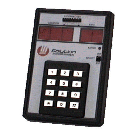
Solution 4+4 Installation Manual Programming With The Hand Held Programmer The Hand Held Programmer (CC814) has five, seven segment displays. The three on the left display the location number, and the two on the right display the data for that particular location. -
Page 21: Programming With The Programming Key
Programming Programming With The Programming Key The Programming Key (CC810) is a unique device that will allow you to easily program your control panel. Inserting the programming key will automatically initiate a data transfer from the programming key to the control panel memory. If you have a new programming key, you should first enter the Installer's Programming Mode, configure the system as required before inserting the programming key. -
Page 22: Installer's Programming Commands
Solution 4+4 Installation Manual Installer’s Programming Commands There are several commands that can be invoked to perform various functions once the Installer's Programming Mode has been entered. To invoke the command, enter the corresponding numerical code followed by the button... -
Page 23: Command 959 - Test Programming Key
Programming Command 959 - Test Programming Key This command initiates a test to be carried out on the programming key. This test is non- destructive and any data in the programming key will remain intact after the test has been completed. -
Page 24: Command 962 - Copy Control Panel Memory To Programming Key
Solution 4+4 Installation Manual Command 962 - Copy Control Panel Memory To Programming Key This command is used to copy the control panel memory to the programming key. How To Copy The Control Panel Memory To The Programming Key Enter Installer's Programming Mode. -
Page 25: Command 963 - Copy From Programming Key To Control Panel
Programming Command 963 - Copy From Programming Key To Control Panel This command is used to copy data from the programming key to the control panel. How To Copy The Programming Key Memory To The Control Panel Enter Installer's Programming Mode. 1234 (ie. -
Page 26: Command 964 - Erase Programming Key
Solution 4+4 Installation Manual Command 964 - Erase Programming Key This command erases all data from the programming key. How To Erase The Programming Key Enter Installer's Programming Mode. 1234 (ie. followed by the button). Connect the programming key onto the pins marked PROGRAMMING KEY on the control panel. -
Page 27: Command 965 - Set Up Domestic Dialling Format
Programming Command 965 - Set Up Domestic Dialling Format Command 965 has been added to make the set up of the domestic dialling format a one step operation. Refer to page 76 for more information on Domestic Reporting Format. After Installer's Programming Mode has been accessed, enter command followed by button. -
Page 28: Command 966 - Enable/Disable Automatic Stepping Of Locations
Solution 4+4 Installation Manual Command 966 - Enable/Disable Automatic Stepping Of Locations This command enables or disables the automatic stepping of locations while programming. When enabled via the hand held programmer, the decimal point of the left most display will reflect the mode of operation. -
Page 29: Command 999 - Display Software Version Number
Installer Code MUST be used for further programming of the control panel. If the Installer Code is not known, the control panel will need to be returned to your EDM Distributor for exchange. A nominal fee applies for this service. -
Page 30: Defaulting The Control Panel
Solution 4+4 Installation Manual Defaulting The Control Panel Solution 4+4 If the control panel does not have "LOCATION 900" programmed as 15, follow the procedure outlined below to successfully default the control panel back to the factory default settings. How To Default The Control Panel Disconnect the AC mains supply and the backup battery from the control panel. -
Page 31: System Indicators And Operations
System Indicators and Operations This section includes the following; • System Indicators and Operations • CP5 Eight Zone Codepad • CP5 Eight Zone LCD Codepad • System Operations • Arming The System In AWAY Mode • Disarming The System From AWAY Mode •... -
Page 32: System Indicators And Operations
Solution 4+4 Installation Manual System Indicators and Operations CP5 Eight Zone Codepad The codepad is the communications interface between you and your alarm system. It allows you to issue commands and offers both visual and audible indications that guide you through the general operation. -
Page 33: Mains Indicator
System Indicators and Operations MAINS Indicator MAINS indicator is used to indicate that the systems AC mains supply is normal or has failed. Indicator Definition AC Mains Power Normal Flashing AC Mains Failure Table 9: MAINS Indicator FAULT Indicator indicator is used to indicate that the system has detected a system fault. Refer to FAULT "Fault Analysis Mode"... -
Page 34: Cp5 Eight Zone Lcd Codepad
Solution 4+4 Installation Manual CP5 Eight Zone LCD Codepad The codepad is the communications interface between you and your alarm system. It allows you to issue commands and offers both visual and audible indications that guide you through the general operation. -
Page 35: System Disarmed
System Indicators and Operations System Disarmed This indicator will illuminate when the system has been disarmed. The indicator will also illuminate when the system has been disarmed. MAINS Indicator indicator is used to indicate that the systems AC mains supply is normal or has MAINS failed. -
Page 36: Off Indicator/Zone Sealed
Solution 4+4 Installation Manual Off Indicator/Zone Sealed indicator will illuminate when the system is in the disarmed state and will flash when a zone becomes unsealed. It will stop flashing when all zones are sealed. On Indicator/Zone In Alarm indicator will illuminate when the system is armed in AWAY Mode and will flash when an alarm occurs. -
Page 37: System Operations
System Indicators and Operations System Operations Arming The System In AWAY Mode There are two methods for arming your system in AWAY Mode. Method one is standard and will always operate. Method two is optional and needs to be enabled in "LOCATION 230" on page 140. -
Page 38: Arming The System In Stay Mode
Solution 4+4 Installation Manual Arming The System In STAY Mode STAY Mode is when the system has been armed with particular zones automatically isolated. Refer to “Zone Options” on page 102 for further information. When there is a need to arm only the system perimeter, this mode is extremely handy. It automatically disables the interior detection zones allowing movement within the protected area while at the same time arming the perimeter zones. -
Page 39: Disarming The System From Stay Mode
System Indicators and Operations Disarming The System From STAY Mode There are two methods for disarming the system from STAY Mode. Method one is standard and will always operate. Method two is optional and needs to be enabled in "LOCATION 230”... -
Page 40: Codepad Duress Alarm
Solution 4+4 Installation Manual Codepad Duress Alarm A codepad duress alarm can be used as a hold up alarm. This will occur when the number is added to the end of any valid user code that is being used to disarm the system. A duress alarm is always silent and can only be made use of if your system is reporting back to a monitoring station or pocket pager. -
Page 41: Isolating Zones
System Indicators and Operations Isolating Zones When a zone has been isolated, access is allowed into that zone at all times. Isolating zones is performed by one of two methods. One way requires the use of a valid user code while the other way does not. -
Page 42: Code To Isolate
Solution 4+4 Installation Manual Code To Isolate Press the button. Enter your Press the button. Three beeps will be heard. * Enter the required to be isolated followed by the button. The zone you have just selected to be isolated will now begin to flash. -
Page 43: Fault Analysis Mode
System Indicators and Operations Fault Analysis Mode Whenever a system fault occurs, the indicator will flash and the codepad will FAULT MAINS beep once every minute. If the MAINS indicator is flashing, this is because the AC mains has been disconnected. There is no need to determine this type of system fault. -
Page 44: Fault Descriptions
Solution 4+4 Installation Manual Fault Descriptions Low Battery A low battery fault will register when the battery supply voltage falls below 10.5 volts or when a dynamic battery test detects a low capacity battery. This fault will clear after a successful dynamic battery test. -
Page 45: System Functions
System Functions This section includes the following; • Installer Code Functions • Master Code Functions • Hold Down Functions... -
Page 46: System Functions
Solution 4+4 Installation Manual System Functions This section deals with the more advanced features that are required for testing and regular maintenance of the system. Features such as Installer Code Functions, Master Code Functions and Hold Down Functions are covered in this section. -
Page 47: Fault Analysis Mode
System Functions Fault Analysis Mode Whenever a system fault occurs, the FAULT or MAINS indicator will flash and the codepad will beep once every minute. If the MAINS indicator is flashing, this is because the AC mains supply has been disconnected. There is no need to determine this type of system fault. -
Page 48: Set The Number Of Days Until The First Test Report
Solution 4+4 Installation Manual Set The Number Of Days Until The First Test Report If test reports are required, "LOCATION 182 - 185" on page 114 will need to be programmed. After this has been carried out, test reports need to be initiated by setting the first test report. If the first test report is not set, the test report will be transmitted in the number of days as programmed in the repeat interval programmed in "LOCATION 182 - 185". -
Page 49: Event Memory Recall Mode
System Functions Event Memory Recall Mode This feature allows you to playback the last forty events that have occurred to the system. The event memory recall mode reports all alarms and arming/disarming of the system in the AWAY Mode and STAY Mode. This function helps with trouble shooting system faults. The events are displayed via the codepad indicators. -
Page 50: Walk Test Mode
Solution 4+4 Installation Manual Walk Test Mode Walk test mode allows you to test detection devices to ensure that they are functioning correctly. Before activating walk test mode, isolate any zones that are not required for testing. Refer to "Isolating Zones" on page 41 for further information. -
Page 51: Turning Telephone Monitor Mode On/Off
System Functions Turning Telephone Monitor Mode On/Off Telephone monitor mode allows the remote codepad to be used for a visual representation of data transmissions between the control panel and the base station receiver. The dialling sequence is also shown in this mode. The codepad will beep once every two seconds while telephone monitor mode is turned on regardless of whether the system is in Installer's Programming Mode or normal operating mode. -
Page 52: Master Code Functions
Solution 4+4 Installation Manual Master Code Functions Master Code Functions are designed to allow those users that have the appropriate priority level to perform certain functions of a supervisory level. 2580 The default Master Code is and is known as User Code 1. It is possible for the system to have multiple Master Codes. -
Page 53: Changing And Deleting User Codes
System Functions Changing and Deleting User Codes This function allows a Master Code holder to add/change or delete any of the system user codes. When changing or deleting user codes, it is important that you know the number of the user you wish to change or delete. - Page 54 Solution 4+4 Installation Manual How To Delete A User Code Enter your followed by and the button. Three beeps will be heard and the indicators will begin to flash. STAY AWAY Enter the (1-8) that you wish to delete followed by the button.
-
Page 55: Changing Domestic Phone Numbers
System Functions Changing Domestic Phone Numbers This option allows a Master Code holder to view and program the required telephone numbers that the system will call in the event of an alarm. For a more detailed description, refer to "Domestic Reporting" on page 82 for further information. How To Change Domestic Phone Numbers Enter your followed by... -
Page 56: Event Memory Recall Mode
Solution 4+4 Installation Manual Zone 1 Zone 2 Zone 3 Zone 4 Zone 5 Zone 6 Zone 7 Zone 8 MAINS Digit Indicator Indicator Indicator Indicator Indicator Indicator Indicator Indicator Indicator ü ü ü ü ü ü ü ü ü... -
Page 57: Walk Test Mode
System Functions Walk Test Mode Walk test mode allows you to test detection devices to ensure that they are functioning correctly. This should be performed on a weekly basis. Before activating walk test mode, isolate any zones that are not required for testing. Refer to "Isolating Zones"... -
Page 58: Fault Analysis Mode
Solution 4+4 Installation Manual Fault Analysis Mode Whenever a system fault occurs, the indicator will flash and the codepad will FAULT MAINS beep once every minute. If the indicator is flashing, this is because the AC mains supply has been disconnected. -
Page 59: Setting The Date And Time
System Functions Setting The Date and Time This function needs to be used when the date and time requires to be changed or the system has been powered down. How To Set The New Date and Time Enter your followed by and the button. -
Page 60: Reset Latching Outputs
Solution 4+4 Installation Manual Reset Latching Outputs This function will reset any device that has been programmed to remain on once it has been activated. This could be a door bell that is required to keep ringing until someone has acknowledged it. -
Page 61: Hold Down Functions
System Functions Hold Down Functions Hold down function have been incorporated to allow easy activation of specific operations. When a button is held down for two seconds, two beeps will be heard and a particular function will operate. The functions available are listed below. Arm The System In AWAY Mode Holding the button down until two beeps are heard will arm the system in AWAY Mode. -
Page 62: Strobe Test
Solution 4+4 Installation Manual Strobe Test Holding the button down will operate the strobe. No other device will operate in this mode. If an EDMSAT (SS914) has been connected to the control panel, this function will also test the strobe on the satellite siren. -
Page 63: Initiate A Modem Call
System Functions Initiate A Modem Call Holding the button down until two beeps are heard will force the control panel to dial the callback telephone number programmed in "LOCATION 32 - 47" on page 83 in an attempt to connect to the remote computer. The remote computer will be required to be running the Alarm Link Software (CC816) and will need to be set to "Waiting For An Incoming Call". - Page 64 Solution 4+4 Installation Manual ISSUE123.DOC Electronics Design and Manufacturing Pty Limited...
-
Page 65: Remote Operations
Remote Operations This section includes the following; • Remote Operations • Remote Arming Via The Telephone • Upload/Download Via Alarm Link Software... -
Page 66: Remote Operations
Solution 4+4 Installation Manual Remote Operations Solution 4+4 This section covers all aspects of operating and programming the control panel other than by a remote codepad or the hand held programmer. There are a number of methods that can be used via the telephone line to gain access to the control panel. These methods will prove to be time saving and easy to perform. -
Page 67: Upload/Download Via Alarm Link Software
Remote Operations Upload/Download Via Alarm Link Software Solution 4+4 control panel can be remotely programmed or controlled via an IBM or compatible personal computer via the Alarm Link Software (CC816). This facility will allow you to make alterations to your customers control panel without the need to leave your office, thus improving customer service and saving you time and money. -
Page 68: Remote Connect With Callback Verification
Solution 4+4 Installation Manual Remote Connect With Callback Verification Remote connect with callback verification offers the highest degree of data security by incorporating a two level security check. The first is the Installer Code combined with the Subscriber ID Number needs to match that of the control panel. -
Page 69: Dialler Reporting Formats
Dialler Reporting Formats This section includes the following; • Dialler Reporting Formats • Contact ID Format • Point ID Codes • Event Codes • General Reporting Formats • Securitel • Domestic Reporting Format • Domestic Dialling Function • Programming Domestic Reporting •... -
Page 70: Dialler Reporting Formats
Solution 4+4 Installation Manual Dialler Reporting Formats When making use of the control panel's dialling and communication features, there are a Solution 4+4 number of transmission formats available. The control panel comes factory default to report in the Contact ID Format. -
Page 71: Point Id Codes
Dialler Reporting Formats Point ID Codes Point ID Event Event Number Description Code Explanation Page Burglary Zones Burglary Zone Specific 1 - 3 Zone Specific 24 Hour Burglary Zones 24 Hour Burglary Tamper Zones 1 – 4 Zone Tamper Zone Specific Fixed 9 - 12 User Specific... -
Page 72: Event Codes
Solution 4+4 Installation Manual Event Codes Event Description Event Description Event Description Medical Alarms 24 Hour Non Burglary Peripheral Troubles Medical 24 Hour Non Burg System Peripheral Pendant Transmitter Gas Detected Polling Loop Open Fail To Report In Refrigeration Polling Loop Short... -
Page 73: General Reporting Formats
Dialler Reporting Formats General Reporting Formats The following formats may be designated to report in either Standard of Extended Formats. In all cases, the standard format will report to the central monitoring station a Subscriber ID Number followed by an Alarm, Trouble, Restore or Open/Close codes. The Expanded 3+1 and Expanded 4+1 Formats will report a Subscriber ID Number followed by an Expansion Code, followed by a second line where the Expansion Code is repeated as the Subscriber ID Number followed by the Reporting Channel (Or User ID) relevant to that report. - Page 74 Solution 4+4 Installation Manual Code Description Code Description Subscriber ID Number Alarm Restore Code SSSS Alarm Trouble Restore Code Channel Number Bypass Restore Code Zero AC Fail Restore Code 1 digit Trouble AC Fail Restore Code 2 Digit Bypass Low Battery Restore Code 1...
-
Page 75: Securitel
Dialler Reporting Formats Securitel Solution 4+4 control panel can communicate to base stations via the Securitel Network using an EDMSTU (CS800). Not all messages can be transmitted via securitel as they can via the communication dialler transmitting in Contact ID Format. Refer to "Table 37: Securitel Reporting Messages"... -
Page 76: Domestic Reporting Format
Solution 4+4 Installation Manual Domestic Reporting Format The locations of the primary telephone number and secondary telephone number which are normally used for base station reporting can be added together making provision to store up to 32 digits for domestic dialling format. The 32 locations are now used to store any number of telephone numbers and subject to the length of each telephone number, it is possible to store 3 or more different phone numbers for domestic dialling. -
Page 77: Programming Domestic Reporting
Dialler Reporting Formats Programming Domestic Reporting Programming the control panel for domestic reporting has been made extremely simple by the use of the Installer's Programming Command 965. Refer to "Command 965 - Set Up Domestic Dialling Format" on page 27 for more information. How To Set Up The Control Panel For Domestic Dialling 1234 Enter Installer's Programming Mode (EG:... - Page 78 Solution 4+4 Installation Manual How To Disable Domestic Dialling Using The Master Code If at any time you wish to cancel domestic dialling for any reason (eg. You are moving house and you do not wish the system to continue calling your work place or mobile phone etc), you may enter the following sequence.
-
Page 79: Basic Pager Reporting Format
Dialler Reporting Formats Basic Pager Reporting Format Basic Pager Format requires some interpretation of the numbers that appear on the display, however, it is possible to differentiate between 1000 different control panels when a number of control panels are reporting to the one pager. How To Setup Basic Pager Reporting "LOCATION 000 - 015"... - Page 80 Solution 4+4 Installation Manual ISSUE123.DOC Electronics Design and Manufacturing Pty Limited...
-
Page 81: Base Station Information
Base Station Information This section includes the following; • Base Station Information • Primary Telephone Number • Secondary Telephone Number • Callback Telephone Number • Dialling Format • Handshake Tone • Transmission Format • Transmission Speed • Subscriber ID Number •... -
Page 82: Base Station Information
Solution 4+4 Installation Manual Base Station Information Solution 4+4 This section outlines the programming information required for the control panel when communicating with base station receivers. Typically these parameters specify the telephone numbers to call, the transmission formats, handshake tones and transmission speeds. -
Page 83: Primary Telephone Number
Dialler Programming Information Primary Telephone Number 0000000000000000 LOCATION 000 - 015 When the control panel requires to transmit a report, the control panel will dial this number in an attempt to contact the monitoring station or pager etc. If the call is successful, the relevant information will be transmitted and the dialler will return back to the stand-by mode. -
Page 84: Dialling Format
Telecommunications Network. The International DTMF dialling option should only be used in those countries that allow both the caller and the receiver to terminate the phone call. Using the incorrect format will disable EDM's patent Telephone Anti-Jamming feature. Option Dialling Format... -
Page 85: Transmission Format
Dialler Programming Information Transmission Format LOCATION 050 Enter the desired transmission format here. This location selects the data format that will be transmitted to the monitoring station receiver. This location also allows you to configure the control panel for domestic or basic pager formats. Option Transmission Format Option... -
Page 86: Receivers And Their Formats
Solution 4+4 Installation Manual Receivers and Their Formats The following is a list of some compatible control room receivers, their specific handshake tones and transmission formats. Use this table only as a guide when selecting the transmission format. Receiver Type... -
Page 87: Ring Count
Dialler Programming Information Ring Count LOCATION 060 This location sets the number of rings before the control panel will answer an incoming call. This should be set at an acceptable level bearing in mind that one ring = "Ring, Ring - Ring, Ring"... - Page 88 Solution 4+4 Installation Manual ISSUE123.DOC Electronics Design and Manufacturing Pty Limited...
-
Page 89: User Codes
User Codes This section includes the following; • Installer Code • User Codes • User Code Priority... -
Page 90: Access Codes
Solution 4+4 Installation Manual Access Codes This section describes the access codes that are used to assign privileges and access functions for user code holders of the system. Two types of user codes exist within the system, the Installer Code and User Codes. Each of these codes allow specific access and operation of the varied functions of the control panel. -
Page 91: User Code Priority
User Codes User Code Priority There are seven different priority levels that can be allocated to the user code. Each priority level allows or restricts the functions that different user code holders may perform. If user code priority levels 4, 6 or 12 have been programmed to any of the available 8 user codes, the method of standard isolating will no longer operate. -
Page 92: Code Retries
Solution 4+4 Installation Manual Code Retries LOCATION 102 Code retries restricts the amount of times an invalid user code can be used in an attempt to operate the system. This location sets the number of incorrect code attempts that will cause an alarm condition. -
Page 93: Zone Information
Zone Information This section includes the following; • Day Alarm Mask • Day Alarm Operation • EOL Resistor Value • Zone Programming • Zone Defaults • Zone Types • Zone Options • Keyswitch Zone Options • Zone Pulse Count • Zone Pulse Count Time... -
Page 94: Zone Information
Solution 4+4 Installation Manual Zone Information Day Alarm Mask LOCATION 101 When programming this location, you will notice that there are four options per location. You may select one, two, three or all four of these options, however, only one number needs to be programmed. -
Page 95: Day Alarm Operation
Zone Information Day Alarm Operation How To Turn Day Alarm On Hold down the button until three beeps are heard. How To Turn Day Alarm Off Hold Down the button until two beeps are heard. If a zone has been programmed for day alarm, the zone can be isolated in the normal way so that it does not register as a day alarm zone. -
Page 96: Eol Resistor Value
Solution 4+4 Installation Manual EOL Resistor Value LOCATION 103 Option Resistor Value Option Resistor Value No EOL Resistor 6K8 (Blue, Grey, Black, Brown) 1% 1K (Brown, Black, Red) 10K (Brown, Black, Orange) 1K5 (Brown, Green, Red) 12K (Brown, Red, Orange) -
Page 97: Connections Of Split Eol Resistors Using N/O Contacts
Zone Information Connections Of Split EOL Resistors Using N/O Contacts Figure 5: Connections Of Split EOL Resistors Using One N/O Contact Figure 6: Connections Of Split EOL Using Two N/O Contacts Electronics Design and Manufacturing Pty Limited ISSUE123.DOC... -
Page 98: Zone Programming
Solution 4+4 Installation Manual Zone Programming Each zone contains eight locations which are divided into two groups of four. The first four locations determine how the zone operates, while the second four locations contain the dialler reporting information. Zone Operating Information Zone Type This location programs the “Zone Type”... -
Page 99: Tamper Zones
Zone Information Tamper Zones Tamper zones are 24 hour zones only. Tamper zones are not programmable like the burglary zones. Tamper zones when unselaed in either the armed or disarmed state will cause an alarm. This alarm condition will be displayed on the codepad by the relevant zone indicator flashing very quickly (0.1 Second On / 0.1 Second Off). -
Page 100: Zone Defaults
Solution 4+4 Installation Manual Zone Defaults Zone 1 Zone 2 Zone 3 Location 104 - 111 Location 112 - 119 Location 120 - 127 2 0 0 0 1 3 0 1 1 0 0 0 1 3 0 1... -
Page 101: Reserved
Zone Information Reserved Instant Zone + Isolated In STAY Mode This zone will act as a Instant zone when the system is armed in the AWAY Mode, but will be automatically isolated when the system is armed in STAY Mode. Handover Zone + Isolated In STAY Mode This zone will act as a Handover zone when the system is armed in the AWAY Mode, but will be automatically isolated when the system is armed in STAY Mode. -
Page 102: Zone Options
Solution 4+4 Installation Manual Zone Options When programming this location, you will notice that there are four options per location. You may select one, two, three or all four of these options, however, only one number needs to be programmed. This number is calculated by adding the option bit numbers together. Program a seven (7) is you require options 1, 2 and 4 simultaneously (ie. -
Page 103: Silent Alarm
Zone Information Silent Alarm A zone programmed to be silent will not trigger the HORN SPEAKER, RELAY, STROBE or EDMSAT outputs. The dialler and all other programmable outputs will function as per their particular programming. Sensor Watch Sensor watch gives the control panel the ability to recognise that detection devices may have stopped working. -
Page 104: Keyswitch Zone Options
Solution 4+4 Installation Manual Keyswitch Zone Options When you select a zone to be a keyswitch input, then the following table relates to the options available to that keyswitch zone. These keyswitch zone options replace zone options only for the zones that have been programmed to operate as a keyswitch zone. -
Page 105: Momentary Arm And Disarm In Away Mode
Zone Information Momentary Arm and Disarm In AWAY Mode If this option has been selected, the system will either arm or disarm from AWAY Mode when using the momentary keyswitch input. Momentary Arm In AWAY Mode If this option has been selected, the system will arm in AWAY Mode when using the momentary keyswitch input. -
Page 106: Zone Pulse Count
Solution 4+4 Installation Manual Zone Pulse Count Zone pulse count is the number of times a zone must be triggered before the zone registers as an alarm. The number of pulses vary between 0 – 15. The zone pulse count value is relative to the time frame (ie. -
Page 107: System Status Information
System Status Information This section includes the following; • Zone Bypass Reports • Zone Trouble Reports • Codepad Duress Report • Codepad Panic Report • Access Denied • AC Fail Report • Low Battery Report • Sensor Watch Time • Open/Close Reports •... -
Page 108: System Status Information
Solution 4+4 Installation Manual System Status Information This section covers features that are involved with the basic house keeping of the system. This includes monitoring of the zones - whether they are isolated from the system or more importantly that they are actually operating, the status of both the AC mains and DC power to the system and codepad generated alarms activated by the user. -
Page 109: Codepad Duress Report
System Reporting Information Codepad Duress Report 1211 LOCATION 156 - 159 Location Description Contact ID Event Code – Hundreds Digit Contact ID Event Code – Tens Digit Or Alarm Or Expansion Digit In 4+2 Format Contact ID Event Code – Units Digit Or Channel Location For All Other Formats Dialler Channel Table 56: Codepad Duress Report Location... -
Page 110: Codepad Panic Report
Solution 4+4 Installation Manual Codepad Panic Report 1201 LOCATION 160 - 163 Location Description Contact ID Event Code – Hundreds Digit Contact ID Event Code – Tens Digit Or Alarm Or Expansion Digit In 4+2 Format Contact ID Event Code – Units Digit... -
Page 111: Access Denied
System Reporting Information Access Denied 4211 LOCATION 164 - 167 Location Description Contact ID Event Code – Hundreds Digit Contact ID Event Code – Tens Digit Or Alarm Or Expansion Digit In 4+2 Format Contact ID Event Code – Units Digit Or Channel Location For All Other Formats Dialler Channel Table 58: System Status –... -
Page 112: Ac Fail Report
Solution 4+4 Installation Manual AC Fail Report 3011 LOCATION 168 - 171 Location Description Contact ID Event Code – Hundreds Digit Contact ID Event Code – Tens Digit Or Alarm Or Expansion Digit In 4+2 Format Contact ID Event Code – Units Digit... -
Page 113: Sensor Watch Report
System Reporting Information Sensor Watch Report 3071 LOCATION 176 - 179 Location Description Contact ID Event Code – Hundreds Digit Contact ID Event Code – Tens Digit Or Alarm Or Expansion Digit In 4+2 Format Contact ID Event Code – Units Digit Or Channel Location For All Other Formats Dialler Channel Table 61: System Status –... -
Page 114: Test Reporting Time
Solution 4+4 Installation Manual Test Reporting Time 00 0 9 LOCATION 182 - 185 (Hour) (Repeat) (Exp) Location Description Actual Hour Of The Day (Tens Digit) Actual Hour Of The Day (Units Digit) Repeat Interval In Days (0 – 15) -
Page 115: Programmable Outputs
Programmable Outputs This section includes the following; • Programmable Outputs • Output Defaults • Redirecting Outputs To The Codepad Buzzer • Output Event Types • Output Polarity • Timing Of Outputs • Pulsing Polarities • One Shot Polarities... -
Page 116: Programmable Outputs
Solution 4+4 Installation Manual Programmable Outputs Solution 4+4 control panel has three fully programmable outputs on the main PCB and one other programmable output that operates the codepad buzzer. These three outputs are factory default to operate a horn speaker, strobe and an internal screamer. -
Page 117: Redirecting Outputs To The Codepad Buzzer
Programmable Outputs Redirecting Outputs To The Codepad Buzzer Multiple output event types can be directed to the codepad buzzer so that it may be used to indicate any number of events. This is achieved by selecting an output and programming it for the required output event type. When you are satisfied that the output is functioning correctly, change the first digit of the output event type (ie. -
Page 118: Output Event Types
Solution 4+4 Installation Manual Output Event Types There are approximately fifty different output event types to choose from. Two numbers designate each output event type. These two numbers need to be programmed into the appropriate locations of the output being used to indicate when the output should operate. - Page 119 Programmable Outputs Entry Warning + Day Alarm Resetting This output combines both Entry Warning and Day Alarm Resetting so that either of these two events will activate the output. If the output has been triggered by either Entry Timer 1, Entry Timer 2, or Entry Guard Timer For STAY Mode, the output will reset once the entry timer has expired or the system has been disarmed.
- Page 120 Solution 4+4 Installation Manual Horn Speaker Monitor Fail If Option 4 – Enable Monitoring Of Horn Speaker in "LOCATION 226" on page 136 has been selected, this output will operate when the horn speaker has been disconnected. The output will reset when the horn speaker has been reconnected.
- Page 121 Programmable Outputs Silent Alarm This output will operate whenever a zone programmed as silent alarm has triggered. The output will reset when the siren run time expires, an audible alarm has triggered, or a valid user code has been entered. Refer to “Zone Options” on page 102 for more information on programming zones to be silent.
- Page 122 Solution 4+4 Installation Manual Communications Failure After 3 Unsuccessful Calls This output will operate when the communication dialler has made 3 unsuccessful calls to the base station receiver. The output will reset when all messages have been transmitted (ie. When the buffer is empty or when all possible attempts have been made).
-
Page 123: Output Polarity
Programmable Outputs Output Polarity There are fifteen different polarities to choose from. Each polarity is designated by a number. This number needs to be programmed into the appropriate location of the output being used to indicate how the output should operate. Option Polarity Option... -
Page 124: Normally Open, One Shot Low With Alarm
Solution 4+4 Installation Manual Normally Open, One Shot Low With Alarm This one shot polarity is normally open circuit and will switch to zero volts when the event occurs. The output will switch back to open circuit once the one shot time has expired, when the event has returned to normal or when the system has been disarmed. -
Page 125: Timing Of Outputs
Programmable Outputs Timing Of Outputs The timing of outputs is calculated by the time base and a multiplier. These two values play different roles depending on the polarity selected. When programming outputs to pulse, both the "On" and "Off" times can be set. One shot polarities can be programmed to operate between 200 ms up to 99 hours in duration. -
Page 126: One Shot Polarities
Solution 4+4 Installation Manual One Shot Polarities The duration or "On" time of an output is determined by the product of the time base and the multiplier. If an output is required to operate for five seconds, program the time settings as follows;... -
Page 127: System Event Timers
System Event Timers This section includes the following; • Entry Timer 1 • Entry Timer 2 • Exit Time • Entry Guard Timer For STAY Mode • Sensor Watch Time • Codepad Lockout Time • Siren Run Time • Siren Sound Rate •... -
Page 128: System Event Timers
Solution 4+4 Installation Manual System Event Timers This section covers the features that involve timing. Features such as entry and exit times, sensor watch time, siren run time and system date and time along with a host of other timers are discussed extensively in this section. -
Page 129: Exit Time
System Event Timers Exit Time Exit time can be programmed to be between 0 and 255 seconds in increments of one second. The remote codepad will always give one long beep at the end of exit time when arming in AWAY Mode or one short beep at the end of exit time when arming in STAY Mode. -
Page 130: Codepad Lockout Time
Solution 4+4 Installation Manual Codepad Lockout Time LOCATION 220 Location Description Increments Of 10 Seconds Table 74: Codepad Lockout Time Locations All codepads will be locked out for the specified time programmed if an invalid code has been entered more times than allowed by the code retry attempts programmed in "LOCATION 102"... -
Page 131: Swinger Shutdown Count
System Event Timers Swinger Shutdown Count LOCATION 223 Location Description Swinger Shutdown Count (0-15) Table 77: Swinger Shutdown Count This location determines the number of times the sirens and dialler can be triggered before any lockout options will take effect. A minimum of one zone must be programmed for lockout siren or dialler for this location to be effective. -
Page 132: System Time
Solution 4+4 Installation Manual System Time 0000 LOCATION 901 – 904 Location Description Current Hour In 24 Hour Time (Tens Digit) Current Hour In 24 Hour Time (Units Digit) Current Minute (Tens Digit) Current Minute (Units Digit) Table 78: System Time Locations... -
Page 133: Options Bits
Options Bits This section includes the following; • Dialler Options 1 • Dialler Options 2 • System Options 1 • System Options 2 • System Options 3 • Consumer Options 1 • Consumer Options 2... -
Page 134: Dialler Options
Solution 4+4 Installation Manual Dialler Options When programming these locations, you will notice that there are four options per location. You may select one, two, three or all four of these options, however, only one number needs to be programmed. -
Page 135: Dialler Options 2
System and Consumer Options Dialler Options 2 LOCATION 225 Option Description Send Open/Close Reports Only If A Previous Alarm Has Occurred Reserved Send Open/Close Reports When In STAY Mode Delay Siren Until Transmission Complete Table 80: Dialler Options 2 Send Open/Close Reports Only If A Previous Alarm Has Occurred This option requires Open/Close reports in “LOCATION 180 - 181”... -
Page 136: System Options 1
System Options 1 LOCATION 226 Option Description Enable Forced Arming Enable EDM Smart Lockout Enable Monitoring Of Horn Speaker Allow Horn Speaker Beeps For Remote Control Operation Table 81: System Options 1 Enable Forced Arming If this option has been selected, the system can be armed with zones unsealed. -
Page 137: System Options 2
System and Consumer Options System Options 2 LOCATION 227 Option Description Enable Radio Key/Keyswitch Interface Or Night Arm Station Enable Handover Delay To Be Sequential Enable Codepad Panic To Be Silent Enable Access Denied To Be Silent Table 83: System Options 2 Enable Radio Key/Keyswitch Interface or Night Arm Station This option must be selected when using the Radio Key/Keyswitch Interface (CC813) or the Night Arm Station (CP105). -
Page 138: System Options 3
Solution 4+4 Installation Manual System Options 3 LOCATION 228 Option Description Reserved Reserved Ignore AC Mains Fail Enable Pulse Count Handover Table 84: System Options 3 Reserved Reserved Ignore AC Mains Fail Indication If this option has been selected, the... -
Page 139: Consumer Options 1
System and Consumer Options Consumer Options 1 LOCATION 229 Option Description Send Test Reports Only If The System Is Armed Enable Operation Of Siren and Strobe In STAY Mode Enable Answering Machine Bypass Only When Armed Enable Codepad Extinguish Mode Table 85: System Options 4 Send Test Reports Only If The System Is Armed If this option has been selected, test reports (Contact ID Event Code 602) will only be sent... -
Page 140: Consumer Options 2
Solution 4+4 Installation Manual Consumer Options 2 LOCATION 230 Option Description Reserved Enable Single Button Arming In AWAY Mode and STAY Mode Enable Single Button Disarming In STAY Mode Enable Alarm Memory Reset On Disarm Table 86: Consumer Options 2... -
Page 141: Optional Equipment
Optional Equipment This section includes the following; • EDMSAT - Satellite Siren (SS914) • Programming Key (CC810) • Alarm Link Software (CC816) • CP5 Eight Zone Codepad (CP508) • CP5 Eight Zone LCD Codepad (CP508L) • Night Arm Station (CP105) •... -
Page 142: Optional Equipment
Solution 4+4 Installation Manual Optional Equipment Solution EDM manufactures numerous accessories that can be used in conjunction with the control panel. These optional pieces of equipment will enhance certain features thus making the system extremely flexible. EDMSAT - Satellite Siren (SS914) The EDMSAT Satellite Siren is a totally self contained unit incorporating a high powered siren and a weatherproof strobe. - Page 143 TF008 Plug Pack (TF008) The TF008 plug packs have been designed to be used with the EDM control panels and the PS100 Power Supply Module. The plug pack includes built in thermal fuses which under overload or fault conditions will blow and eliminate any possible fire threat due to excessive heat build up inside the casing.
- Page 144 Solution 4+4 Installation Manual Radio Key/Keyswitch Interface (CC813) This interface was designed to allow simple interfacing of a momentary keyswitch or radio equipment for remote control operations to operate the control panel. If the R/K terminal is used, a number of momentary keyswitches may be connected in parallel for multiple arm/disarm locations.
- Page 145 Optional Equipment Figure 8: Radio Key/Keyswitch Interface (CC813) Connection Diagram Electronics Design and Manufacturing Pty Limited ISSUE123.DOC...
- Page 146 Solution 4+4 Installation Manual Figure 9: Radio Key/Keyswitch Interface (CC813) Connection Diagram ISSUE123.DOC Electronics Design and Manufacturing Pty Limited...
-
Page 147: Terminals And Descriptions
Terminals and Descriptions This section includes the following; • Terminal Definitions and Descriptions • Glossary Of Terms • Solution 4+4 Wiring Diagram • Solution 4+4 Component Overlay • Telecom Connection Diagrams... -
Page 148: Terminal Definitions And Descriptions
DC siren needs to be connected to the GND terminal. A link (JP2) is provided on the PCB for connecting the COM terminal to either GND or 12V. This link should be connected to +12V as shown in "Figure 10: Solution 4+4 Wiring Diagram" on page 151. The relay is rated at 1 Amp/30 VDC. -
Page 149: Glossary Of Terms
Terminals and Descriptions Glossary Of Terms Term Description Alarm Condition Is when your alarm system is armed and one of the detection devices are violated. A 24 hour zone (eg. Smoke detector) may trigger when your system is armed or disarmed. Answering Machine Answering machine bypass has been incorporated so that it is possible to make a connection with Bypass... - Page 150 Solution 4+4 Installation Manual Term Description Handover Delay When your system is armed and zone one is violated, the entry delay starts timing. If zone two is then violated the entry delay time is handed over to zone two and so on through zones three and four.
-
Page 151: Solution 4+4 Wiring Diagram
Terminals and Descriptions Solution 4+4 Wiring Diagram Figure 10: Solution 4+4 Wiring Diagram Electronics Design and Manufacturing Pty Limited ISSUE123.DOC... -
Page 152: Solution 4+4 Component Overlay
Solution 4+4 Installation Manual Solution 4+4 Component Overlay Figure 11: Solution 4+4 Component Overlay ISSUE123.DOC Electronics Design and Manufacturing Pty Limited... -
Page 153: Telecom Connection Diagrams
Terminals and Descriptions Telecom Connection Diagrams Figure 12: Telecom Connection Diagrams For Solution 4+4 Electronics Design and Manufacturing Pty Limited ISSUE123.DOC... - Page 154 Solution 4+4 Installation Manual ISSUE123.DOC Electronics Design and Manufacturing Pty Limited...
-
Page 155: Appendices
Appendices This section includes the following; • Telephone Anti-Jamming • Test Reports Only When Armed... -
Page 156: Telephone Anti-Jamming
Solution 4+4 Installation Manual Appendix A Telephone Anti-Jamming There are many companies today importing American designed products that claim to have Anti-Jamming and believe it or not, they push this feature as if it were a major break through in control panel technology. -
Page 157: Test Reports Only When Armed
Appendix B Test Reports Only When Armed Solution 4+4 control panel allows for test reports to be transmitted to the base station receiver to verify that the dialler functional. So what you might say, as most alarm diallers allow you to do this. - Page 158 Solution 4+4 Installation Manual ISSUE123.DOC Electronics Design and Manufacturing Pty Limited...
-
Page 159: Specifications
Specifications This section includes the following; • Warranty Statement • Specifications • Software Version Number • Advice To Users • New Zealand Telepermit Notes... -
Page 160: Warranty Statement
Solution 4+4 Installation Manual Warranty Statement Electronics Design and Manufacturing Pty Limited warrants this product to be free from defects in material and workmanship for a period of three years from the date of manufacture as indicated by the date stamp and /or the serial number on the product. -
Page 161: Advice To Users
Advice To Users The Austel permit that has been issued for this product is subject to the following conditions. • Solution 4+4 Control Panel may only be powered by an EDM TF008 Plug Pack (Approval Number Q92128). New Zealand Telepermit Notes •... - Page 162 Solution 4+4 Installation Manual ISSUE123.DOC Electronics Design and Manufacturing Pty Limited...
-
Page 163: Programming Sheets
Programming Sheets... - Page 164 Solution 4+4 Installation Manual Location 000 – 015 Page 83 Primary Telephone Number 0 0 0 0 0 0 0 0 0 0 0 0 0 0 0 0 Location 016 – 031 Page 83 Secondary Telephone Number 0 0 0 0 0 0 0 0 0 0 0 0 0 0 0 0 Location 032 –...
- Page 165 Programming Sheets Location 104 – 151 Page 100 Zones Zone 1 Zone 2 Zone 3 Location 104 - 111 Location 112 - 119 Location 120 - 127 2 0 0 0 1 3 0 1 1 0 0 0 1 3 0 1 1 0 0 0 1 3 0 1 Zone 4 Location 128 - 135...
- Page 166 Solution 4+4 Installation Manual Location 152 – 153 Page 108 Bypass Codes (Zones 1 To 4) Location 154 – 155 Page 108 Trouble Codes (Zones 1 To 4) Location 156 – 159 Page 109 Codepad Duress 1 2 1 1 Location 160 –...
- Page 167 8 = Delay Siren Until Transmission Complete Location 226 Page 136 System Options 1 1 = Enable Forced Arming 2 = Enable EDM Smart Lockout 4 = Enable Monitoring Of Horn Speaker 8 = Enable Horn Speaker Beeps For Remote Control Operation Location 227 Page 137...
- Page 168 Solution 4+4 Installation Manual ISSUE123.DOC Electronics Design and Manufacturing Pty Limited...
-
Page 169: Index
Index... - Page 170 Solution 4+4 Installation Manual Command 961 - Reset Control Panel Back To Factory Default Settings ................23 Command 962 - Copy Control Panel Memory To Programming 2 Wire Smoke Detector Interface........143 Key ................24 24 Hour Burglary Zone ............101 Command 963 - Copy From Programming Key To Control 24 Hour Fire Zone .............101...
- Page 171 Index Entry Guard Timer For STAY Mode ........129 Installer Code Function – Send Test Report ......51 Entry Time ..............128, 149 Installer Code Function - Set Number Of Days Until First Test Entry Timer 1 ..............128 Report ................48 Entry Timer 2 ..............128 Installer Code Function - Telephone Monitor Mode .....
- Page 172 Solution 4+4 Installation Manual Output Event Type - Codepad Fire Alarm......120 Outputs - On/Off..............58 Output Event Type - Codepad Medical Alarm ....120 Outputs - One Shot Polarities ..........126 Output Event Type - Codepad Panic Alarm ......120 Outputs - Pulsing Polarities ..........125 Output Event Type - Codepad Tamper .......120...
- Page 173 Index Siren Sound Rate ...............130 Software Version Number..........29, 160 Unsealed ................150 Solution Codepad Mimic Board .........143 Upload/Download Via Alarm Link........67 Solution Relay Output Interface .........143 User Code................. 150 Speaker Beeps ..............136 User Code Priority .............. 91 Specifications ..............160 User Codes .................
Need help?
Do you have a question about the Solution 4+4 and is the answer not in the manual?
Questions and answers