Table of Contents
Advertisement
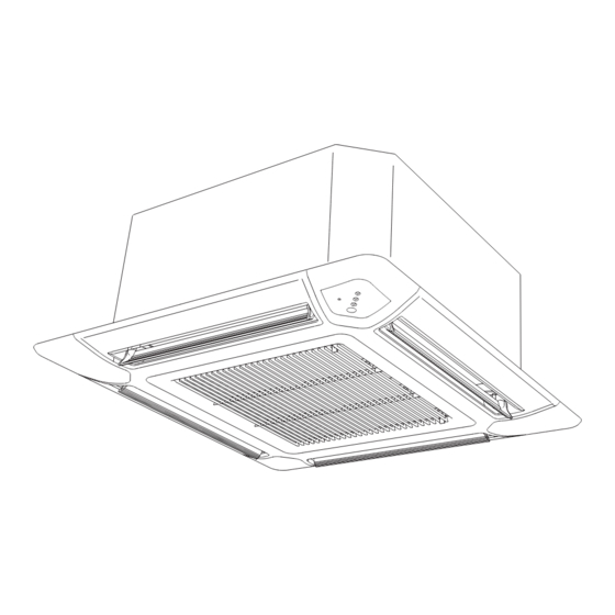
AIR CONDITIONER
INDOOR UNIT
Cassette type
INSTALLATION MANUAL
For authorized service personnel only.
Contents
1.
SAFETY PRECAUTIONS ............................................. 2
2.
2.1. Precautions for using R410A refrigerant.............. 2
2.2. Special tool for R410A ......................................... 2
2.3. Accessories ......................................................... 3
2.4. Decoration panel accessories ............................. 3
2.5. Optional parts ...................................................... 3
3.
3.1. Selecting an installation location ......................... 4
3.2. Installation dimension .......................................... 4
3.3. Installation the unit............................................... 4
4.
4.1. Selecting the pipe material .................................. 5
4.2. Pipe requirement ................................................. 6
4.3. Flare connection (pipe connection) ..................... 6
4.4. Installing heat insulation ...................................... 7
5.
INSTALLING DRAIN PIPES ......................................... 7
6.
6.1. Electrical requirement .......................................... 8
6.2. Wiring method ..................................................... 9
7.
7.1. Load batteries (R03/LR03 × 2) .......................... 10
7.2. Installing the Remote control unit holder ........... 11
8.
8.1. Remove the intake grille .................................... 11
8.2. Installing the panel to indoor unit ....................... 12
8.3. Attaching the intake grille................................... 12
9.
FUNCTION SETTING
9.1. Operation method .............................................. 13
9.2. Function setting ................................................. 14
9.4. Special installation methods .............................. 16
10. TEST RUN .................................................................. 18
11. CHECK LIST ............................................................... 19
12. ERROR CODES ......................................................... 19
13. CUSTOMER GUIDANCE ........................................... 20
PART NO. 9379124003-02
Advertisement
Table of Contents

Subscribe to Our Youtube Channel
Related Manuals for Fujitsu RCF24LBL


Summary of Contents for Fujitsu RCF24LBL
-
Page 1: Table Of Contents
AIR CONDITIONER INDOOR UNIT Cassette type INSTALLATION MANUAL For authorized service personnel only. Contents SAFETY PRECAUTIONS ..........2 REMOTE CONTROLLER SETTING 7.1. Load batteries (R03/LR03 × 2) ......10 ABOUT THE UNIT 7.2. Installing the Remote control unit holder ... 11 2.1. -
Page 2: Safety Precautions
1. SAFETY PRECAUTIONS 2.2. Special tool for R410A • Be sure to read this Manual thoroughly before installation. WARNING • The warnings and precautions indicated in this Manual con- • To install a unit that uses R410A refrigerant, use dedicat- tain important information pertaining to your safety. -
Page 3: Accessories
2.3. Accessories 2.4. Decoration panel accessories WARNING Name and Shape Q’ty Description Connector cover For covering connector • For installation purposes, be sure to use the parts sup- plied by the manufacturer or other prescribed parts. The use of non-prescribed parts can cause serious ac- cidents such as the unit to fall, water leakage, electric shock, or fi... -
Page 4: Installation Work
3. INSTALLATION WORK 3.2. Installation dimension • The ceiling rear height as shown in the fi gure. Especially, the installation place is very important for the split type air conditioner because it is very diffi cult to move from Strong and durable ceiling place to place after the fi... -
Page 5: Pipe Installation
3.3.1. Position the ceiling hole and hanging bolts 3.3.3. Leveling Using a level, or vinyl hose fi lled with water, fi ne adjust so that Ceiling openings and hanging bolt installation diagram. the body is level. WARNING • When fastening the hangers, make the bolt positions uniform. -
Page 6: Pipe Requirement
Pipe outside Width across fl ats Width across 4.2. Pipe requirement diameter [mm (in.)] of Flare nut [mm] 6.35 (1/4) CAUTION 9.52 (3/8) • Refer to the Installation Manual of the outdoor unit for 12.70 (1/2) description of the length and the diameter of connecting 15.88 (5/8) pipe or for difference of its elevation. -
Page 7: Installing Heat Insulation
ith two wrenches. 5. INSTALLING DRAIN PIPES ng wrench Note Install the drain pipe. Torque wre • Install the drain pipe with downward gradient (1/50 to 1/100) and so there are no rises or traps in the pipe. • Use general hard polyvinyl chloride pipe (VP25) [outside di- Indoor unit pipe ameter 32 mm (1-1/4”)] and connect it with adhesive (polyvi- Connection pipe... -
Page 8: Electrical Wiring
6. ELECTRICAL WIRING 6.1. Electrical requirement Power supply cable WARNING Earth cable Transmission cable • Electrical work must be performed in accordance with Conductor size this Manual by a person certifi ed under the national or 1.5(MIN.) regional regulations. Be sure to use a dedicated circuit for the unit. -
Page 9: Wiring Method
6.2.2. Connection cable preparation 6.2. Wiring method • Keep the earth wire longer than the other wires. 6.2.1. Connection diagrams (Standard pair) Power supply cable or Earth wire Transmission cable Wired remote Transmission cable controller Indoor unit Outdoor unit How to connect wiring to the terminals. Black (For strand wiring) White... -
Page 10: Remote Controller Setting
6.2.3. Wiring procedure 7. REMOTE CONTROLLER SETTING Remove the control box cover and install each connection wire. Refer to the installation manual enclosed with the remote con- Control box cover Screw trol unit when the wired remote control unit (option ) is used. 7.1. -
Page 11: Installing The Remote Control Unit Holder
8. DECORATION PANEL INSTALLATION 7.2. Installing the remote control unit holder • Installation according to the Installation instruction sheet CAUTION Decoration panel. • Check that the indoor unit correctly receives the signal • Be sure to confi rm there is no gap between the panel and from the remote control unit, then install the remote main unit after installing the Decoration panel. -
Page 12: Installing The Panel To Indoor Unit
Connect the connector. 8.2. Installing the panel to indoor unit Wire (display): WHITE Install the decoration panel on the indoor unit. Wire (louver): WHITE Wire (louver): RED “DRAIN” mark “PIPE” mark Indoor unit side • Arrange the wires as illustrated below. •... -
Page 13: Operation Method
The remote control unit resets to signal code A when the 9. FUNCTION SETTING batteries in the remote control unit are replaced. If you use a signal code other than signal code A, reset the signal code CAUTION after replacing the batteries. •... -
Page 14: Function Setting
Setting Other Functions 9.2. Function setting • The following settings are also possible, depending on the operating conditions. (The setting value is factory-set to Setting the Ceiling Height “00”.) • Select the setting values in the table below according to the height of the ceiling. -
Page 15: Selecting The Remote Control Unit Signal Code
Indoor unit setting 9.3. Selecting the remote control unit signal Jumper wire Remote control unit code signal code Connect Connect A (Primary setting) [When using the wireless remote controller] Disconnect Connect When two or more air conditioners are installed in a room and Connect Disconnect the remote control unit is operating an air conditioner other... -
Page 16: Special Installation Methods
Remote controller setting 9.4. Special installation methods Turn on all of the indoor units. When the indoor units are turned on, error codes 01 This possible only the wired remote control. (Option) and 31 will be displayed; however, these error codes will be deleted by setting the remote controller. - Page 17 9.4.2. Group control system Function Indoor unit Unit number Setting Value Number A number of indoor units can be operated at the same time ① using a single remote controller. ② (1) Wiring method (indoor unit to remote controller) ∼ ∼...
-
Page 18: Test Run
9.4.3. Dual remote controllers 10. TEST RUN • Two separate remote controllers can be used to operate the indoor units. CHECK ITEMS • The timer and self-diagnosis functions cannot be used on the Is operation of each button on the remote control unit slave unit of remote controller. -
Page 19: Check List
The OPERATION, TIMER and FILTER Lamp operate as fol- 11. CHECK LIST lows table according to the error contents. Pay special attention to the check items below when install- OPERATION TIMER FILTER Error contents Lamp ing the indoor unit(s). After installation is complete, be sure to Lamp Lamp ○... -
Page 20: Customer Guidance
[Troubleshooting at the remote control LCD](Op- 13. CUSTOMER GUIDANCE tion) This is possible only on the wired remote control. Explain the following to the customer in accordance with the [Self-diagnosis] operating manual: If an error occurs, the following display will be shown. Starting and stopping method, operation switching, tem- (“EE”...
Need help?
Do you have a question about the RCF24LBL and is the answer not in the manual?
Questions and answers