Makita ER2650LH Technical Information
Petrol string trimmer
Hide thumbs
Also See for ER2650LH:
- Instruction manual (184 pages) ,
- Original instruction manual (56 pages) ,
- Instruction manual (20 pages)
Table of Contents
Advertisement
T
ECHNICAL INFORMATION
Models No.
Description
C
ONCEPT AND MAIN APPLICATIONS
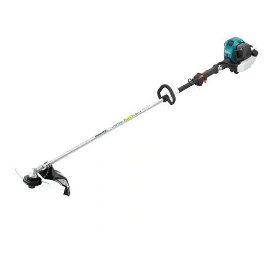
Model ER2650LH is a petrol string trimmer equipped with
25.4cm³ 4-stroke engine in compliance with
all known exhaust emission regulations.
S
pecification
Model
Type
Displacement: cm³ (cu.in.)
Engine
Fuel
Max. output: kW (PS)
Max. torque: N.m
at max. output power
Speed:
at no load
min.
¹=spm
ˉ
with nylon cutting head
(nylon cord diameter: mm)
Engine oil
Carburetor
Starting system
Fuel tank capacity: L (US oz)
Primer pump
Clutch
Spindle size
Cutting width: mm (")
Handle style
Rapid start
Dry weight*
: kg (lbs)
2
*1: However, equipped with mechanical decompression
*2: without guard, cutting tool
S
tandard equipment
Nylon cutting head .......................................................................................... 1
Socket wrench (for 10-16) .............................................................................. 1
Hex wrench 4 .................................................................................................. 1
Pin 4 ................................................................................................................ 1
Accessory bag ................................................................................................. 1
Oil set (oil bottle containing 80mL engine oil) ............................................... 1
Note: The standard equipment for the tool shown may vary by country.
O
ptional accessories
Nylon cutting heads [Bump & feed 4, Ultra Auto 4]
ER2650LH
Petrol String Trimmer
EH026
4-stroke
25.4 (1.5)
Straight unleaded gasoline
0.77 (1.1)
1.1 (at 5,500 min.
7,000
10,000
7,900
(2.4)
SAE10W-30 oil
in the Class SF or higher of API classification
Diaphragm
Recoil starter, with mechanical decompression
0.6 (20.3)
Yes
Yes
M8 x 1.25, Right-handed
412 (16-1/4)
Loop handle
No*
1
4.8 (10)
H
W
L
Dimensions: mm (")
Length (L)
1,621 (64)
Width (W)
310 (12-1/4)
Height (H)
479 (18-7/8)
¹)
ˉ
PRODUCT
P 1/ 14
Advertisement
Table of Contents

Related Manuals for Makita ER2650LH


Summary of Contents for Makita ER2650LH
- Page 1 P 1/ 14 Models No. ER2650LH Description Petrol String Trimmer ONCEPT AND MAIN APPLICATIONS Model ER2650LH is a petrol string trimmer equipped with 25.4cm³ 4-stroke engine in compliance with all known exhaust emission regulations. Dimensions: mm (") Length (L) 1,621 (64)
- Page 2 (2) Clean the matching surface where the gasket is placed to maintain its sealing performance. [3] LUBRICANT / ADHESIVE APPLICATION (1) Apply Makita grease N No.2 to Spiral spring in Recoil starter and the spline ends of Shaft. (2) Apply Liquid gasket; ThreeBond 1215, to the matching surface of Crank case and Cylinder block when assembled.
- Page 3 P 3/ 14 epair [4] DISASSEMBLY/ASSEMBLY [4]-2. Engine and Shaft DISASSEMBLING (1) Disconnect lead wire and grounding wire by removing each connector after Air cleaner cover is removed. (Fig. 1) (2) Remove Control cable from Insulator by loosening nuts of the adjust screw and disconnecting inner cable from Swivel of Carburetor.
- Page 4 P 4/ 14 epair [4] DISASSEMBLY/ASSEMBLY [4]-3. Shaft pipe complete DISASSEMBLING (1) Loosen two M5x25 Hex socket head bolts and remove Clamp cover B and Loop handle. (Fig. 7) (2) Remove 4x18 Tapping screws (4pcs) and M5x14 Hex socket head bolts, then separate Lever case R and L.
- Page 5 P 5/ 14 epair [4] DISASSEMBLY/ASSEMBLY [4]-4. Head case complete (cont.) DISASSEMBLING (2) Disaasemble Cutter shaft and Ball bearings from Head case complete. (Fig. 10) Fig. 10 2. Fix Head case with vise and lock Cutter 1. Make Hex wrench 5 square shape by grinding its two diagonal edges holder with 1R308.
- Page 6 P 6/ 14 epair [4] DISASSEMBLY/ASSEMBLY [4]-5. Clutch DISASSEMBLING Disassemble Clutch by removing Shoulder hex bolt M6x25 (2pcs) with Cordless impact driver using 13mm Socket bit. (Fig. 12) Fig. 12 13mm Note: Socket bit • Clutch is removed with Cordless impact driver without locking Piston.
- Page 7 P 7/ 14 epair [4] DISASSEMBLY/ASSEMBLY Fig. 15 [4]-7. Ignition Plug cap CHECKING PLUG CAP (1) Remove Plug cap from Spark plug and test the continuity Earth terminal between Plug cap spring in Plug cap and Earth terminal of Ignition coil. Plug cap spring It is in order when Tester shows 2.0kΩ±0.5kΩ.(Fig.
- Page 8 P 8/ 14 epair [4] DISASSEMBLY/ASSEMBLY [4]-8. Flywheel DISASSEMBLING Remove M8 Flange nut and pull out Fly wheel with 1R364. (Fig. 20) Fig. 20 1. Remove M8 Flange nut by turning it counterclockwise using Cordless impact driver with 13mm Socket bit. Note: •...
- Page 9 Reel. Set Inner hooked end of and Knob, then make knots at both ends Spiral spring on the rib inside of Reel. 2. Apply Makita grease N No.2 a little to the entire Spiral spring. Approx. 10mm Starter knob...
- Page 10 P 10/ 14 epair [4] DISASSEMBLY/ASSEMBLY [4]-10. Carburetor Fig. 24 DISASSEMBLING 1. Remove Air cleaner cover. 2. Remove Air cleaner elements. Cleaner plate Air cleaner (1) Remove Air cleaner cover and Air cleaner assembly element disassemble Air cleaner. (Fig. 24) Air cleaner cover (felt)
- Page 11 P 11/ 14 epair [4] DISASSEMBLY/ASSEMBLY [4]-10. Carburetor (cont.) Fig. 26 ASSEMBLING (Nipple to connect yellow tube of Tank) Carefully assemble each part in right direction and order. (Fig. 25) 1R127 AIRTIGHT TEST Connect 1R127 to the nipple of Carburetor as drawn in Fig. 26. Give air pressure from 1R127 and check if the pressure gauge indicates Nipple of Carburetor to connect 0.05Mpa for around 10 seconds, then there is no problem with Carburetor.
- Page 12 P 12/ 14 epair [4] DISASSEMBLY/ASSEMBLY [4]-13. Spark arrester MAINTENANCE (1) Remove Cylinder cover. Fig. 31 (2) Remove Exhaust Muffler. Exhaust muffler Spark arrester (3) Remove Spark arrester from Exhaust muffler and sweep it if dirt or soot is on Spark arrester. (Fig. 31) Replace it with a new one if spark arrester has a breakage or fray.
- Page 13 1. Insert Piston pin through Piston and Rod of Crankshaft, and fix it with Clip by using an awl. Note: • Apply Makita grease N No.2 a little to Needle bearing in Rod of Crankshaft. • Piston is bilateral symmetry and can be fixed in either direction.
- Page 14 P 14/ 14 epair [4] DISASSEMBLY/ASSEMBLY [4]-14. Engine block (cont.) ASSEMBLY (3) Adjust the valve clearance by following the steps in Fig. 35. Fig. 35 3. Assemble Cam lifter (2pcs), Rod 2.5 (2pcs) and Rocker arm assembly 1. Align the markings on Ignition coil (2pcs) to Cylinder block assembly.
Need help?
Do you have a question about the ER2650LH and is the answer not in the manual?
Questions and answers