GE JKS10 Technical Service Manual
27-in. built-in wall ovens
Hide thumbs
Also See for JKS10:
- Installation instructions manual (40 pages) ,
- Owner's manual (24 pages) ,
- Brochure (24 pages)

Related Manuals for GE JKS10


Summary of Contents for GE JKS10
- Page 1 GE Consumer & Industrial Technical Service Guide June 2008 27-in. Built-In Wall Ovens JKS10 JKP30 JKP35 JKP55 JKP70 JKP75 JKP90 PK916 PK956 ZEK938 ZEK958 31-9163 GE Appliances General Electric Company Louisville, Kentucky 40225...
- Page 2 If grounding wires, screws, straps, clips, nuts, or washers used to complete a path to ground are removed for service, they must be returned to their original position and properly fastened. GE Consumer & Industrial Technical Service Guide Copyright © 2008 All rights reserved.
-
Page 3: Table Of Contents
Table of Contents Auxiliary Control Board ..............................38 Bake Element ..................................42 Broil Element ..................................34 Component Locator Views ............................25 Control Board Testing ..............................56 Control Compartment Access .............................36 Control Features ................................06 Control Panel Assembly ..............................37 Control Voltage ..................................50 Convection Bake Element .............................36 Convection Fan Blade ..............................35 Convection Fan Motor ..............................45 Cooling Fan ..................................43... -
Page 4: Introduction
Introduction The new 27-in. wall ovens have superior style and performance. These ovens feature electronic controls that utilize the precision of modern digital technology. Additional features include: • Convection Bake (Multi-Rack) ― Provides ideal convection baking for multiple racks of food, ensuring superb results •... -
Page 5: Nomenclature
J K P 5 5 S M 1 S S Product Color SS = Stainless Steel GE Cooking Product ZE = Monogram Electric P = Profi le J = GE Series Indicator for Engineering and Confi guration Product Service Only K = 27-in. Wall Oven GE Confi guration only... -
Page 6: Control Features
Control Features Models ZEK938 and ZEK958 Double oven control shown. (Appearance may vary.) Features 1 BAKE. Press to select the bake function. 9 COOK TIME. Use for Timed Bake, Timed Convection Bake and Timed Convection 2 BROIL HIGH/LOW. Press to select the Roast operations. - Page 7 Models PK956 and PK916 Double oven control shown. Oven Control, Clock and Timer Features and Settings Bake Pad Delay Start Pad Press to select the bake function. Use along with Cooking Time or Self Clean Std/Low pads to set the Broil Hi/Lo Pad oven to start and stop automatically at a Press to select the broil function.
- Page 8 Throughout this manual, features and appearance may vary from your model. Double oven control shown. Oven Control, Clock and Timer Features and Settings Bake Pad Self Clean Pad Press to select the bake function. Press to select self-cleaning function. See the Using the self-cleaning oven section.
- Page 9 Throughout this manual, features and appearance may vary from your model. Double oven control shown Oven Control, Clock and Timer Features and Settings Bake Pad Delay Start Pad Press this pad to select the bake function. Use along with Cooking Time or Self Clean pads to set the oven to start and stop Broil Hi/Lo Pad automatically at a time you set.
- Page 10 Model JKP90 Lower Oven Control, Clock and T Display Shows the time of day, oven temperature, whether the oven is in the bake, broil or self-cleaning mode and the times set for the timer or automatic oven operations. NOTE: The time on the lower oven display is shown in hours and minutes (1:30 is one hour, 30 minutes).
- Page 11 How to Set the Oven for Baking or Roasting Press the Bake pad. Rack Position Type of Food 27” Oven 30” Oven On models with number pads, press them in order to set the desired Frozen pies B or C C or D temperature.
- Page 12 Using the clock and timer. ge.com To Set the Clock The clock must be set to the correct time Press the Clock pad. of day for the automatic oven timing On models with number pads, press functions to work properly. The time of...
-
Page 13: Using The Probe
Using the probe. For many foods, especially roasts and poultry, internal food temperature is the best test for doneness. The temperature probe takes the guesswork out of roasting by cooking foods to the exact doneness you want. NOTE: Double oven models have a probe in the upper oven only. - Page 14 How to Set the Oven for Convection Roasting when Using the Probe The display will flash PROBE and the oven When the internal temperature of the meat reaches the number you control will signal if the probe is inserted into the outlet, and you have not set a have set, the probe and the oven For best results when roasting large turn off and the oven control...
- Page 15 Using the convection oven. Convection Bake ■ NOTE: The convection fan will cycle on and off Ideal for evenly browned baked foods cooked on multiple racks. while cooking to best distribute hot air in the ■ oven. Good for large quantities of baked foods. ■...
- Page 16 Using the timed features for convection cooking. ge.com On double oven models, you can use timed baking or roasting in one oven while using self-clean in the other; you can also use timed baking or roasting in both ovens at the same time.
- Page 17 Adjust the oven thermostat—Do it yourself! You may find that your new oven cooks differently than the one it replaced. Use your new oven for a few weeks to become more familiar with it. If you still think your new oven is too hot or too cold, you can adjust the thermostat yourself. Do not use thermometers, such as those found in grocery stores, to check the temperature setting of your oven.
- Page 18 Using the self-cleaning oven. (on some models) ge.com The oven door must be closed and all controls must be set correctly for the cycle to work properly. Before a Clean Cycle ■ We recommend venting your kitchen On models with press pad controls...
-
Page 19: Special Features Of Your Oven Control
Special features of your oven control. ge.com Your new press pad control has additional features that you may choose to use. The following are the features and how you may activate them. The special feature modes can only be activated while the display is showing the time of day. They remain in the control’s memory until the steps are repeated. - Page 20 Tone Volume (on some models) This feature allows you to adjust the tone For each time the level is changed, volumes to a more acceptable volume. There are a tone will sound to provide an three possible volume levels. indication of the volume level. Press the Bake and Broil Hi/Lo pads Choose the desired sound level (1 BEEP, 2 BEEP, 3 BEEP).
- Page 21 Changing the Speed of the + or – Pads (on some models) As you use the + or – pads when setting a Press any + pad to increase the time or temperature, you may notice the display speed up to the number 5. changes slowly.
- Page 22 Using the Sabbath Feature. (Designed for use on the Jewish Sabbath and Holidays.) (on some models) The Sabbath feature can be used for baking/roasting only. It cannot be used for convection, broiling, self-cleaning or Delay Start cooking. NOTE: The oven light comes on automatically (on some models) when the door is opened and goes off when the door is closed. The bulb may be removed.
- Page 23 How to Set the Oven for Warming How to Set the Oven for Proofi ng Warm keeps cooked foods warm for up to The proofing feature maintains a warm 3 hours after the cooking function is finished, environment useful for rising yeast-leavened or it can be activated independently to keep products.
-
Page 24: Operational Notes
• The oven and the oven interior lights will turn on Sales Mode immediately and stay on until the oven is turned off. The oven control can be operated in SALES MODE. When the unit is connected to 120 VAC from L1–N, •... -
Page 25: Bake Element
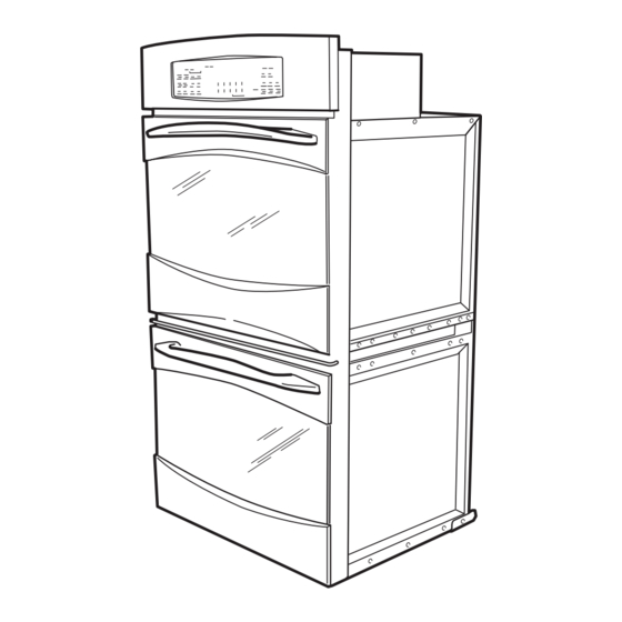
Component Locator Views Double Wall Oven (Profi le shown) Control Panel Door Lock Meat Probe Outlet Broil Element Light Oven Temperature Sensor Convection Fan Oven Door Gasket Hidden Bake Element Oven Door Door Lock Broil Element Light Oven Temperature Sensor Hidden Bake Element Oven Door Gasket Oven Door... - Page 26 Control Compartment Top of Oven (Double Oven Shown) Cooling Fan Capacitor Metal Air Divider Auxiliary Control Board Electronic Oven Control (EOC) Door Lock Assembly and Thermal Switches (Double Oven Shown) Metal Air Divider Door Lock Thermal Switch (Continued next page) –...
- Page 27 Back of Oven ( Double Oven Shown, All Rear Covers Shown Removed) Convection Fan Thermal Line Break Thermal Cutout (TCO) Bake Element Cooling Fan Thermal Line Break Thermal Cutout (TCO) Bake Element – 27 –...
-
Page 28: Oven Component Access Chart
Oven Component Access Chart WARNING: • The single and double wall ovens are heavy and require two people to remove them from the installation. Care should be taken when removing and installing. • Sharp edges may be exposed when servicing. Use caution to avoid injury. Wear Kevlar gloves or equivalent protection. -
Page 29: Door Assembly
Oven Components To replace the door: Door Assembly With the door at the same angle as the removal The oven door can be separated into 2 assemblies. position, seat the indentation of the hinge arm The outer assembly consists of the outer panel into the bottom edge of the hinge slot. - Page 30 To remove the outer door assembly: 2. Remove the four T-15 Torx screws (2 on each side) that attach each door hinge to the inner Remove the door. door. Carefully turn the door over and remove both door hinges. Place the inner door assembly, gasket side up, on a protective surface.
- Page 31 Remove the six ¼-in. hex-head screws that hold Arrows on the side of the inner glass assembly the heat barrier to the inner door. Remove the indicate the direction in which the inner oven door barrier. glass is installed. The arrows should be pointing toward the oven cavity.
-
Page 32: Oven Removal
4. Pull the oven slightly forward to access some Oven Removal components (See Oven Component Access Chart or, if removing it completely, utilize a table or The replacement of certain components require platform in front of the oven and pull the oven oven removal. -
Page 33: Oven Separation (Jkp90 Only)
3. Remove the ¼-in. hex-head screws that hold the Oven Separation (JKP90 Only) side access panel to the oven. The double wall oven has 17 hex-head screws on the top side Oven separation is only necessary on the JKP90 panel and 14 hex-head screws on the bottom Micromod Wall Oven. -
Page 34: Control Board Testing
Oven Temperature Sensor Broil Element The oven temperature sensor can be tested from Note: The resistance of this component can be the EOC. (See .) The resistance Control Board Testing tested from the EOC. (See Control Board Testing of the temperature is: The broil element will not work if the temperature Ω... - Page 35 Vent Tube/Smoke Eliminator Convection Fan Blade The oven vent tube/smoke eliminator is located in The convection fan blade is located on the back wall the top left front corner of the oven cavity above of the oven cavity and is removed separately from the broiler element shield.
-
Page 36: Control Compartment Access
Convection Bake Element Control Compartment Access Note: The resistance of this component can be Note: It may be necessary to partially remove the tested from the EOC. (See oven from the installation to avoid damage to the Control Board Testing customer's woodwork. -
Page 37: Control Panel Assembly
Open the microwave door. key panel. 3. Remove two T-20 torx screws from control panel Note: The GE, Profi le, and Monogram series control assembly. panels are slightly different. Verify the model number of the unit before making any repairs or tests. -
Page 38: Auxiliary Control Board
To remove the auxiliary control board: PK916 Series Control Panel Shown Gain access to the control compartment. (See To disassemble the GE series control panel: Control Compartment Access 1. Disconnect and remove the ribbon connector Mark and disconnect all connectors from the from the electronic oven control and the key auxiliary board. -
Page 39: Lock Assembly
The cam on the motor performs two functions: Lock Assembly Positions the lock hook in the door to prevent The motorized door lock assembly is located above opening during the cleaning operation. the oven. The assembly consists of a lock motor cam and switch assembly, lock hook, mounting Operates the lock switches, which tell the plate, cooling fan switch, spring, plunger, and oven... - Page 40 Door Lock - Unlocked Position Hold the control panel and open the oven door. Place the control panel on the protected oven door as shown. Strip Circuit Lift the metal air divider. LOW TEMP THERMAL SW UNLOCK SW Mark and disconnect the connectors from the LOCK SW lock assembly.
-
Page 41: Thermal Switches
To remove the lock assembly on lower double Thermal Switches ovens and JKP90: The thermal switches are located on the fl oor of the 1. On JKP90, remove the microwave trim from the component compartment in front of the fan motor. microwave. - Page 42 6. Disconnect the wires from the bake element. Bake Element 7. Carefully move the insulation to access and Note: The resistance of this component can be remove the ¼-in. hex-head screw that holds the tested from the EOC. (See Control Board Testing bake element to the oven.
- Page 43 To remove the cooling fan in the lower oven: Cooling Fan Remove the oven from the installation and A cooling fan is located above each oven. On upper remove the rear access panels. (See Oven and single ovens, the cooling fan is in the rear wall Removal.) on the left side of the control compartment.
-
Page 44: Door Hinge Receivers
3. Remove four ¼-in. hex-head screws and the Door Hinge Receivers duct cover from the oven. To remove the door hinge receivers: Remove the side access panels. (See Oven Removal. Carefully lift the insulation from the outside of the oven. Duct Cover Remove the four T-15 screws (2 on each side) that hold each hinge receiver to the oven frame. -
Page 45: Convection Fan Blade
Disconnect the convection fan motor wire Convection Fan Motor harness. Note: The resistance of this component can be Remove the three ¼-in. hex-head screws that tested from the EOC. (See Control Board Testing hold the convection fan motor to the back of the oven. -
Page 46: Oven Light Assembly
Pull the oven light housing from the oven liner. Oven Light Assembly The GE and Profi le series ovens have one light assembly in each oven cavity. The Monogram series oven has two light assemblies in each cavity. The halogen light assembly is located on the top of the oven. -
Page 47: Electronic Oven Control (Eoc)
Electronic Oven Control Overview The Electronic Oven Control (EOC) system consists of the control, key panel, oven sensor, and door lock assembly. Caution: Components are electrically HOT on the control when voltage is connected to the range. Note: Voltage must be present across terminals L1 and N for the control to operate. Note: Temperature/Mode Selection is necessary for the operation of the relay contacts. -
Page 48: Cooling Fan
Electronic Oven Control for Single Wall Oven RY502 RY500 RY501 RY620 RY540 RY650 RY655 RY630 RY660 RY650 Door Lock Motor Switch Meat Probe, Door Switch Relay, Thermal Switch, Oven Sensor RY540 Double Line Break L1 Power to EOC RY630 Cooling Fan Convection Fan RY620 Oven Light Convection Fan... - Page 49 Electronic Oven Control for Double Wall Oven Ribbon Cable to Key Panel Upper Broil Relay Upper Door Lock Motor Switch, Temperature Upper Bake Relay Sensor, and Meat Probe Lower Broil Relay Lower Door Lock Motor Switch, Temperature Lower Bake Relay Sensor, and Meat Probe Upper Lock Motor Relay L1 Power to Transformer...
-
Page 50: Diagnostics And Service Information
Voltage must be present across terminals L1 to N for the control to operate. • Temperature/Mode Selection is necessary for the operation of the relay contacts. Models JKS10, JKP30, & JKP35 *If the oven light is not working, make the following TERMINALS... - Page 51 Model JKP70, PK916, & ZEK938 *If the oven light is not working, make the following TERMINALS VOLTAGE checks: L1-N 120 VAC all the time • Check the oven light bulb to verify it works. COM to N 120 VAC all the time L1-L2 240 VAC all the time •...
-
Page 52: Key Panel Test
• Check the capacitor. Key Panel Test Models JKS10, JKP30, & JKP35 Note: The key panel and the electronic control are a single component. Press each pad on the key panel followed by the Clear/Off pad. If the key panel is functioning properly, the following should occur: •... - Page 53 Model JKP55 Note: The key panel and the electronic control are separate components and must be tested individually. Press each pad on the key panel followed by the Clear/Off pad. If the key panel is functioning properly, the following should occur: •...
-
Page 54: Oven Sensor And Door Switch Test
Resistance Measurement Chart Terminals Models Circuit Connector Ohms Upper Lower 1080 Ω @ Rm. Temp. JKS10 Oven Sensor 4 to 6 1080 Ω @ Rm. Temp. JKP30 Oven Sensor 4 to 6 JKP35 0 Ω 1 to 3... -
Page 55: Error Codes
F code is stored (F2 and F8 are 1 minute or less). On the JKS10, JKP30, JKP35, & JKP55, the F codes can be recalled by pressing the Timer, Clock, and Min Down buttons simaltaneously. While F codes are displayed, pressing Min Up and Hr Down simaltaneously will clear them. - Page 56 Control Board Testing The resistance of various components can be checked from the electronic oven control by the service technician to quickly identify failed or improper operation of certain oven components. Note: Colored dots on relays match color of wire. Hidden Bake Element To test the hidden bake element, the resistance should read approximately 27...
- Page 57 Line Voltage Testing To test the line voltage at the board, the black wire is L1, The white wire is neutral, and the red wire is L2. The voltage should be approximately 120 VAC between L1 and N and approximately 240 VAC between L1 and L2.
-
Page 58: Schematics And Wiring Diagrams
Schematics and Wiring Diagrams WARNING: Disconnect electrical power before servicing. Caution: Label all wires prior to disconnection. Wiring errors can cause improper and dangerous operation. Verify operation after servicing. Model JKS10 RELAY COILS 850 Ω 24 VDC (Continued Next Page) – 58 –... - Page 59 Model JKP30 ° ° ° ° OVEN TEMP ° 1100 Ω @ ROOM TEMP 2650 Ω @ CLEAN TEMP (Continued Next Page) – 59 –...
- Page 60 Model JKP35 (Continued Next Page) – 60 –...
- Page 61 Model JKP55 (Continued Next Page) – 61 –...
- Page 62 Models JKP70, PK916, & ZEK938 ° ° (Continued Next Page) – 62 –...
- Page 63 Models JKP75, PK956, & ZEK958 (Continued Next Page) – 63 –...
- Page 64 Model JKP90 RELAY COILS 650Ω, 24 VDC ° ° ° ° OVEN TEMP 1100 Ω @ ROOM TEMP 2650 Ω @ CLEAN TEMP ° ° Ω , ROOM TEMP Ω , ROOM TEMP – 64 –...
-
Page 65: Warranty
This warranty is extended to the original purchaser and any succeeding owner for products purchased for home use within the USA. If the product is located in an area where service by a GE Authorized Servicer is not available, you may be responsible for a trip charge or you may be required to bring the product to an Authorized GE Service location for service. - Page 66 – 66 –...
Need help?
Do you have a question about the JKS10 and is the answer not in the manual?
Questions and answers