Advertisement
Visit www.carrier.com
Installation and Start-Up Instructions
ZONE
HOLD
I
NFINITY
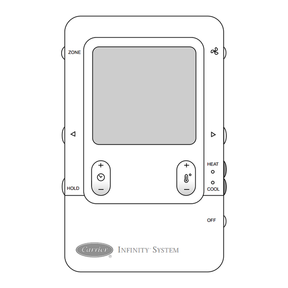
Infinity™ Zone Control
SYSTXCCUIZ01
NOTE: Read the entire instruction manual before starting the
installation.
This symbol → indicates a change since the last issue.
TABLE OF CONTENTS
SAFETY CONSIDERATIONS .....................................................1
INTRODUCTION ..........................................................................1
INSTALLATION AND START-UP OVERVIEW ......................1
INSTALLATION ...........................................................................2
INITIAL POWER-UP....................................................................5
QUICK START..............................................................................7
INSTALL / SERVICE MENUS....................................................8
OPERATIONAL INFORMATION.............................................13
TROUBLESHOOTING ...............................................................14
SAFETY CONSIDERATIONS
Read and follow manufacturer instructions carefully. Follow all
local electrical codes during installation. All wiring must conform
to local and national electrical codes. Improper wiring or installa-
tion may damage the Infinity™ Zone System. Recognize safety
information. This is the safety-alert symbol
symbol on the equipment and in the instruction manual, be alert to
the potential for personal injury. Understand the signal words
DANGER, WARNING, and CAUTION.
Manufacturer reserves the right to discontinue, or change at any time, specifications or designs without notice and without incurring obligations.
Book 1 4
PC 101
Catalog No. 809-50025
Tab misc. misc.
HEAT
COOL
OFF
S
™
YSTEM
A03149
. When you see this
Printed in U.S.A.
Infinity™ Zone Control
These words are used with the safety-alert symbol. DANGER
identifies the most serious hazards, which will result in severe
personal injury or death. WARNING signifies a hazard, which
could result in personal injury or death. CAUTION is used to
identify unsafe practices, which may result in minor personal
injury or product and property damage. NOTE is used to highlight
suggestions which may result in enhanced installation, reliability,
or operation.
INTRODUCTION
The Infinity Zone System consists of several intelligent commu-
nicating components which includes the Infinity Zone Control (or
User Interface), Smart Sensors, Damper Control Module, variable-
speed furnace or FE fan coil, 2-speed AC or HP, which continually
communicate with each other via a four-wire connection called the
ABCD bus. Commands, operating conditions, and other data are
passed continually between components over the ABCD bus. The
result is a new level of comfort, versatility, and simplicity.
All Infinity furnaces or fan coils are variable-speed and multi stage
for maximum flexibility, efficiency, and comfort. They support
controlled ventilation, humidification, dehumidification, and air
quality control. Either an Infinity dual capacity (communicating),
or a standard 24 vac controlled outdoor unit may be used.
When using conventional outdoor units, the Infinity furnace or fan
coil provides the 24 volt signals needed to control them. Also, the
Infinity™ Damper Control Module (P/N SYSTXCC4ZC01) al-
lows connection of a conventional HRV or ERV without the need
for a separate wall control.
All system components are controlled through the wall mounted
Infinity™ Zone Control, which replaces the conventional thermo-
stat and provides the homeowner with a single wall control for all
features of the system.
INSTALLATION AND START-UP OVERVIEW
This instruction covers installation of the Infinity™ Zone Control
only. Physical installation instructions for the indoor and outdoor
equipment, Damper Control Module, and accessories are provided
with each unit.
Setup, commissioning, operation, and troubleshooting of the
Infinity Zone System is covered only in this installation instruc-
tion. It is the guide to connecting the system components and
commissioning the system once all physical components are
installed. Special screen prompts and start-up capabilities are
provided in the Infinity System to simplify and automate the initial
commissioning of the system.
• Install Infinity™ Zone Control according to this instruction.
• Install indoor unit, outdoor unit, and accessories according to
their instructions.
• Wire complete system according to this instruction.
• Setup, commission, and operate system according to this
instruction to assure a smooth and trouble free start-up.
Form UIZ01-1SI
Pg 1
SYSTXCCUIZ01
03-04
Replaces: NEW
Advertisement

Subscribe to Our Youtube Channel
Related Manuals for Carrier Infinity SYSTXCCUIZ01


Summary of Contents for Carrier Infinity SYSTXCCUIZ01
-
Page 1: Table Of Contents
SYSTXCCUIZ01 Infinity™ Zone Control Visit www.carrier.com Installation and Start-Up Instructions These words are used with the safety-alert symbol. DANGER identifies the most serious hazards, which will result in severe personal injury or death. WARNING signifies a hazard, which ZONE could result in personal injury or death. CAUTION is used to identify unsafe practices, which may result in minor personal injury or product and property damage. -
Page 2: Installation
INSTALLATION WIRING CONSIDERATIONS — Ordinary thermostat wire is recommended. Use 22 AWG or larger for normal wiring applica- STEP 1 — CHECK EQUIPMENT AND JOB SITE tions. Continuous wire lengths over 100 ft. should use 20 AWG or INSPECT EQUIPMENT — File claim with shipping company, larger. - Page 3 A04017 Fig. 5—Thin Decorative Backplate Fig. 2—Infinity Zone Control A03185 Recessed terminal block in wall 1 ˝ wide by 2 ˝ high Recessed Mount Interlocking Tabs (4) A03190 Fig. 6—Recessed Mount Assembly A03186 Fig. 3—Recessed Mount Backplate Surface Mount Backplate to wall Interlocking Tabs (4) A03191 Fig.
- Page 4 A03193 Fig. 10—4–Wire ABCD Connector ELECTRICAL OPERATION HAZARD Failure to follow this caution may result in equipment damage or improper operation. Improper wiring of the ABCD connector will cause the Infinity Zone System to operate improperly. Check to make A03188 sure all wiring is correct before proceeding with installation Fig.
-
Page 5: Initial Power-Up
indoor furnace or fan coil OAT terminals. When OAT sensor is HUMIDIFIER CONNECTION — A 24vac bypass or fan applied, the Infinity System will provide enhanced system features powered humidifier may be installed. and benefits. NOTE: Do Not Use a traditional humidistat to control humidifier See wiring diagram Fig. - Page 6 NOTE: If the variable-speed indoor equipment (furnace or fan SECTION 4 — SELECTING ACCESSORIES coil) cannot be found, the User Interface will display ″CANNOT Once the indoor and outdoor equipment have been found or COMMUNICATE WITH INDOOR UNIT″. This MUST be entered, the following screens will appear allowing the Installer to corrected before the initial power up sequence can continue.
-
Page 7: Quick Start
SECTION 6 — EQUIPMENT SUMMARY 9. Adjust desired heating humidity level using either (+/−) button. EQUIPMENT SUMMARY 10. Press the blue COOL button to select cooling humidity. SETUP FURNACE 58MVP0100-12 38TDB036300 COMPLETE! 11. Adjust desired cooling humidity level using FILTER HUMIDIFIER either(+/−)button. -
Page 8: Install / Service Menus
INSTALL MENU 11. Exit the scheduling mode by either closing the door or pressing the SCHEDULE button. 12. If changes are made, you will be asked to ″SAVE CHANGES INSTALL YES/NO″ TO ADD, UNINSTALL OR RE-INSTALL EQUIPMENT, INSTALL / SERVICE MENUS PRESS RIGHT SIDE BUTTON INSTALL/SERVICE... - Page 9 SMART RECOVERY: OFF DELAY: • On or Off, (default=On) • 90 seconds Applies to programmable operation only. Will start recovery 90 • 120 seconds (default) minutes prior to schedule change in both heating and cooling • 150 seconds mode. • 180 seconds ENGLISH/METRIC DISPLAY: Amount of time the blower will continue to run after heating has •...
- Page 10 ELECT HEAT LOCKOUT / LOCKOUT TEMP: VENTILATOR: NOTE: Only appears if ventilator is installed. • NONE (default) • +5 to 55 deg. F CLEAN INTERVAL: Outside temperature above which the electric heat will not operate. • 60 to 180 days of actual operation (default=90) In dual fuel applications, heat pump will not operate below Interval at which the Clean Ventilator Pre-filter notification will selected temperature.
- Page 11 Checkout = HEAT PUMP HEATING AIRFLOW LIMITS: • HIGH HEAT RUNTIME: 5 min. • Low • LOW HEAT RUNTIME: 5 min. • Medium • DEFROST: NO • High (default) The heat pump heating mode can be exercised with this menu •...
- Page 12 LOCKOUT TIMER: Service = ZONING STATUS • Seconds ZONE STATUS: If a lockout timer is active, this will show the current time value. This screen will show each zone in the system with the corre- See furnace manual for details on lockout timers. sponding damper position (POS), and CFM being delivered to each zone.
-
Page 13: Operational Information
OPERATIONAL INFORMATION Heat/Cool Set points (Desired Temperatures) Zone Selection: A minimum difference of 2° (default) is enforced between heating and cooling desired temperatures. This is done by allowing one • Press top left ZONE button to select zones. setting to ″push″ the other to maintain this difference. This Continuous Fan Operation difference is adjustable via the Install/Service menu under Ther- Pressing FAN button will scroll through the following:... -
Page 14: Troubleshooting
TROUBLESHOOTING CRITICAL MALFUNCTION SCREEN Infinity Zone Control™ does not power up. OUTSIDE: 94 FAN: AUTO 1. Recheck wiring to ABCD on all devices. ˚ ALERT ! 2. Make sure all colors match for every terminal. 3. Make sure power is applied to the indoor unit, and the amber HVAC SERVICE 1 800 555-1212 LED is lit on indoor control circuit board. - Page 15 TWO-SPEED OUTDOOR UNIT Defrost Error (defrost signal on for more than 15 minutes) Code 85 - VC voltage at standby The user can press the right side button to dismiss the notice. The regular run mode screen will then appear except ″SYSTEM Code 86 - High capacity compressor lockout MALFUNCTION″...
- Page 16 Copyright 2004 CARRIER Corp. • 7310 W. Morris St. • Indianapolis, IN 46231 uiz01-1si Manufacturer reserves the right to discontinue, or change at any time, specifications or designs without notice and without incurring obligations. Book 1 4 Tab misc. misc. PC 101 Catalog No.
Need help?
Do you have a question about the Infinity SYSTXCCUIZ01 and is the answer not in the manual?
Questions and answers