Advertisement
Table of Contents
- 1 Rules for Safe Operation
- 2 Electrical Requirements
- 3 Identification of Main Parts and Components
- 4 On/Off Switch
- 5 Unpacking and Setup
- 6 Installation and Assembly
- 7 Basic Adjustments & Controls
- 8 On /Off Power Switch
- 9 Changing Spindle Speed
- 10 Tailstock Movement
- 11 Periodic Maintenance
- 12 Recommended Optional Accessories
- 13 Parts List
- Download this manual
SETUP & OPERATION MANUAL
FEATURES
Quick lock control levers easily position
tool rest.
Large 12" inboard bowl turning capacity.
Stable cast-iron frame, head & tailstock to
reduce chatter and vibration for smoother
turning.
Maximum distance of 17 5⁄16" between
centers.
Maximum distance of 49" between cen-
ters with optional bed extension (Item #25-
205).
Quick release belt tension lever for faster,
easier speed changes.
Three variable speed ranges: 300 to 900,
600 to 1800 & 1200 to 3600 rpm.
Digital spindle speed display.
12" tool rest with sturdy 1" diameter sup-
port post.
Forward/reverse switch.
Features positive spindle indexing in 10°
increments - total 36 index positions.
SPECIFICATIONS
SPINDLE SPEED
(VARIABLE) 300 TO 3600 RPM
SWING OVER BED
12" (304 MM)
SWING OVER TOOL REST
9 ¼" (236 MM)
SWING OVER SIDE BED
19 ¼" (490 MM)
SWING OVER SIDE TOOL REST
16 ⅝" (424 MM)
DISTANCE BETWEEN CENTERS
17 5⁄16" (440 MM)
SPINDLE THREAD
1" (25.4 MM) - 8 TPI
TAILSTOCK THROUGH HOLE
⅜" (10 MM)
MORSE TAPER
MT #2
2 ⅛" (55 MM)
SELF EJECTING TRAVEL
TOOL REST
12" (305 MM)
3 ⅛" (80 MM)
FACE PLATE
INDEXING POSITION
36 X 10°
MOTOR M1
¾ HP , 110 V, 8 A, 2500 RPM
WEIGHT
146 LBS (66.5 KG)
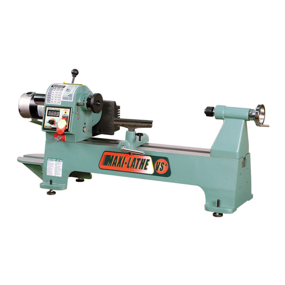
"MAXI-LATHE VS+"
12" X 17" WOOD LATHE
variable speed
MODEL
#25-200
VERSION 2_REVISION 1 - November 04/13 (S/N:25855611)
© Copyright General® International 11/2013
Advertisement
Table of Contents

Subscribe to Our Youtube Channel
Related Manuals for General International MAXI-LATHE VS+ 25-200

Summary of Contents for General International MAXI-LATHE VS+ 25-200
- Page 1 SETUP & OPERATION MANUAL “MAXI-LATHE VS+” 12″ X 17″ WOOD LATHE FEATURES Quick lock control levers easily position variable speed tool rest. Large 12″ inboard bowl turning capacity. Stable cast-iron frame, head & tailstock to reduce chatter and vibration for smoother turning.
- Page 2 GENERAL® INTERNATIONAL 8360 Champ-d’Eau, Montreal (Quebec) Canada H1P 1Y3 Telephone (514) 326-1161 • Fax (514) 326-5555 • www.general.ca THANK YOU for choosing this Variable Speed Maxi Lathe VS+ model 25-200 by ® General International. This unit has been carefully tested and inspected before shipment and if properly used and maintained, will provide you with years of reliable service.
-
Page 3: Rules For Safe Operation
RULES FOR SAFE OPERATION To help ensure safe operation, please take a moment to learn the machine’s applications and limitations, as well as poten- tial hazards. General® International disclaims any real or implied warranty and holds itself harmless for any injury that may result from improper use of its equipment. -
Page 4: Electrical Requirements
ELECTRICAL REQUIREMENTS BEFORE CONNECTING THE MACHINE TO THE POWER SOURCE, VERIFY THAT THE VOLTAGE OF YOUR POWER SUPPLY CORRE- SPONDS WITH THE VOLTAGE SPECIFIED ON THE MOTOR I.D. NAMEPLATE. A POWER SOURCE WITH GREATER VOLTAGE THAN NEEDED CAN RESULT IN SERIOUS INJURY TO THE USER AS WELL AS DAMAGE TO THE MACHINE. IF IN DOUBT, CONTACT A QUAL- IFIED ELECTRICIAN BEFORE CONNECTING TO THE POWER SOURCE. -
Page 5: Identification Of Main Parts And Components
VARIABLE SPEED MAXI-LATHE VS+ 25-200 IDENTIFICATION OF MAIN PARTS AND COMPONENTS ON/OFF SWITCH Ù HEADSTOCK (KEY SWITCH) TOOL REST FACE PLATE TOOL REST CARRIAGE BELT GUARD TOOL REST LOCKING LEVER BELT TENSION RELEASE LEVER TOOL REST CARRIAGE LEVER BELT TENSION LOCK LEVER LIVE CENTER MOTOR TAILSTOCK LOCKING LEVER... -
Page 6: Unpacking And Setup
Carefully unpack and remove the wood lathe and its components from the box and check for damaged or miss- ing items as per the list of contents below. NOTE: Please report any damaged or missing items to your General International distributor immediately. LIST OF CONTENTS... -
Page 7: Installation And Assembly
INSTALLATION & ASSEMBLY For your convenience this lathe is shipped from the factory partially assembled and requires only minimal assem- bly and set-up before being put into service. Before starting the assembly, make sure that the switch is in the “OFF” position and that the power cord is unplugged. - Page 8 Top View Side View Release the headstock locking lever A and pull the Use the 2 mounting bolts and lock washers D to headstock pivot pin B outwards and pivot the attach the outboard bed extension to the bed as headstock 180º.
-
Page 9: Basic Adjustments & Controls
Install the supplied tool rest locking lever on to the tool rest extension post and set the post aside for use during outboard turning. BASIC ADJUSTMENTS & CONTROLS ON /OFF POWER SWITCH: The wood lathe is equipped with a rocker type ON/OFF switch located on the headstock A, that is equipped with a lock-out key. To prevent unwanted or unauthorized start-up or usage remove the lock-out key and store it in a safe place B. -
Page 10: Changing Spindle Speed
CHANGING SPINDLE SPEED: This model 25-200 MAXI-LATHE VS + is equipped with an electronic variable speed controller allowing the user to change the speed of the spindle (within the 3 different spindle speed ranges: 300-900, 600-1800 & 1200-3600 rpm) by simply turning the speed control dial. - Page 11 7. To verify the belt positioning and ensure the belt will run smooth on the pulleys; rotate the fly wheel A by hand to turn the spindle while observing the belt movement. If the belt moves smoothly re-install the belt guard – if the belt wobbles between the pulleys repeat steps 3-6 as needed.
-
Page 12: Tailstock Movement
Back View 2. To remove the live center from the tailstock quill, loosen the tailstock quill locking lever F and move the quill out by turning the quill movement handwheel G until the quill end is nearly inside the tailstock and the live center can be re- moved by hand. - Page 13 3. With the face plate removed from the lathe, mount the workpiece onto the faceplate with wood screws (not included) through the mounting holes on the face plate. Make sure the screws are not so long that they will enter the area of the workpiece where the material is to be removed.
-
Page 14: Periodic Maintenance
PERIODIC MAINTENANCE • Keep the unit clean and free of dust by wiping with a cloth or vacuuming off any woodchips or dust after each use. • All bearings are sealed and permanently lubricated and no further lubrication is required. •... -
Page 15: Recommended Optional Accessories
RECOMMENDED OPTIONAL ACCESSORIES A large range of optional aftermarket accessories can be used with this lathe. Your local dealer may be able to offer suggestions based on what is readily available in your area. Key issues to keep in mind when shopping for aftermarket accessories are: Headstock and tailstock feature a MT#2 taper –... -
Page 16: Parts List
PARTS LIST 25-200 IMPORTANT: When ordering replacement parts, always give the model number, serial number of the machine and part number. Also a brief description of each item and quantity desired PART N0. REF. N0. DESCRIPTION SPECIFICATIONS 25200-001 910092-000 MOTOR DC90V/0.75HP 25200-002 921457-000... - Page 17 PARTS LIST 25-200 PART N0. REF. N0. DESCRIPTION SPECIFICATION 25200-051-3 572469-000 CONTROL BOX LABEL GENERAL 25200-051-4 937338-000 SAFETY SWITCH 25200-051-5 172302-000 CONTROL BOX COVER 25200-051-6 021501-000 RELIEF 10 X 14 X 3.5 25200-051-7 240057-000 VR KNOB 25200-051-8 490464-000 B50K 25200-051-9 001101-205 TAP SCREW M3 X 1.06P X 6...
- Page 18 PARTS LIST - 25-200 PART N0. REF. N0. DESCRIPTION SPECIFICATIONS 25200-096 040003-000 ALLEN WRENCH 3 MM 25200-097 042602-000 SAFETY GOGGLES 25200-098 040002-000 ALLEN WRENCH 2.5 MM 25200-099 380764-902 INDEX PIN 25200-100 000303-202 ROUND HEAD SCREW M5 X 0.8P X 8 25200-101 380765-906 CHAIN...
- Page 19 29 30 62 63...
- Page 20 MODEL #25-200 8360 Champ-d’Eau, Montreal (Quebec) Canada H1P 1Y3 Tel.: (514) 326-1161 Fax: (514) 326-5565 - Fax: (514) 326-5555 - Parts & Service / Order Desk orderdesk@general.ca www.general.ca Follow us:...
Need help?
Do you have a question about the MAXI-LATHE VS+ 25-200 and is the answer not in the manual?
Questions and answers