Table of Contents
Advertisement
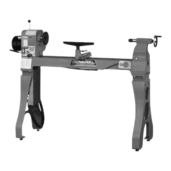
SETUP & OPERATION MANUAL
FEATURES
Specifically designed and built for profes-
sionals who want superior performance.
Heavy-duty, cast-iron bed and stand for
added stability and minimal vibration.
Headstock swivels 360° with positive stops
at 45°, 90°, 135°, 180° and 270° and quick-
lock for outboard turning.
Electronic inverter for variable speed
adjustment between 45 and 3750 RPM.
Digital spindle speed readout.
Forward or reverse rotation.
Movable emergency switch can be
placed to suit the operator.
Quiet, highly efficient, low power consump-
tion motor.
Low/High speed change lever for quick
belt position changing.
14" tool rest and a 6" face plate included.
SPECIFICATIONS
SPINDLE SPEEDS (VARIABLE)
45 - 1000, 85 - 2000, 150 - 3750 RPM
SWING OVER BED CAPACITY
16" (406 MM)
SWING OVER TOOL REST CAPACITY
14" (356 MM)
DISTANCE BETWEEN CENTERS
43" (1092 MM)
SPINDLE THREAD
1 1⁄4" (32 MM) - 8 TPI
TAILSTOCK THROUGH HOLE
3⁄8" (10 MM)
HEADSTOCK TAPER
MT2
SPINDLE CENTER LINE TO FLOOR
44 1⁄2" (1130 MM)
HEADSTOCK MOVEMENT
PIVOT 360° AND SLIDE
INDEXING POSITIONS
36 X 10°
OVERALL DIMENSIONS (L X W X H)
64" X 15" X 48" (1626 X 381 X 1219 MM)
MOTOR
2 HP , 220 V, 3 PH, 6.2 A
INPUT POWER
110 V, 1PH ONLY
WEIGHT
418 LBS (190 KG)
16" x 42" WOOD TURNING LATHE
MODEL
#
25-650ABC M1
VERSION 1_REVISION 1 - SEPTEMBER 13/11 (25905211)
© Copyright General® International 09/2011
Advertisement
Table of Contents

Related Manuals for General International 25-650ABC M1

Summary of Contents for General International 25-650ABC M1
- Page 1 HEADSTOCK TAPER MODEL SPINDLE CENTER LINE TO FLOOR 44 1⁄2” (1130 MM) HEADSTOCK MOVEMENT 25-650ABC M1 PIVOT 360° AND SLIDE INDEXING POSITIONS 36 X 10° OVERALL DIMENSIONS (L X W X H) 64” X 15” X 48” (1626 X 381 X 1219 MM) MOTOR 2 HP , 220 V, 3 PH, 6.2 A...
- Page 2 General ® International model 25-650ABC M1 16” X 42” Wood Lathe. This wood lathe has been carefully tested and inspected before ship- ment and if properly used and maintained, will provide you with years of reliable service. For...
- Page 3 GENERAL & GENERAL INTERNATIONAL WARRANTY ® ® All component parts of General®, General® International and Excalibur by General International ® products are carefully inspected during all stages of production and each unit is thoroughly inspected upon completion of assembly. Limited Lifetime Warranty Because of our commitment to quality and customer satisfaction, General®...
-
Page 4: Table Of Contents
TABLE OF CONTENTS Rules for safe operation ............Electrical requirements . -
Page 5: Rules For Safe Operation
RULES FOR SAFE OPERATION To help ensure safe operation, please take a moment to learn the machine’s applications and limitations, as well as poten- tial hazards. General® International disclaims any real or implied warranty and holds itself harmless for any injury that may result from improper use of its equipment. -
Page 6: Electrical Requirements
(45-1000, 85-2000 and 150 -3750 RPM) with digital spindle speed display, the 25-650ABC M1 is ideal for turnings such as chair or table legs and columns, as well as bowls of various sizes. A sim- ple belt re-positioning on the drive pulleys, allows the operator to select the desired speed range and the electronic speed controller allows for further fine-tuning within each speed range. -
Page 7: Identification Of Main Parts And Components
16" X 42" WOOD TURNING LATHE 25-650ABC M1 IDENTIFICATION OF MAIN PARTS AND COMPONENTS HEADSTOCK A- MOTOR N- TOOL REST B- HEADSTOCK O- TOOL REST SWIVEL ARM C- BELT TENSION RELEASE LEVER P- TOOL REST SWIVEL ARM LOCKING D- INDEXING PIN... -
Page 8: Unpacking
NOTE: Please report any damaged or missing items to your General International distributor immediately. LIST OF CONTENTS A - WOOD LATHE ........1 B - STAND CABINET . -
Page 9: Placement Within The Shop
PLACEMENT WITHIN THE SHOP THIS MODEL 25-650ABC 16" X 42" WOOD LATHE IS VERY HEAVY. DO NOT OVER-EXERT. THE HELP OF AT LEAST TWO ASSISTANTS WILL BE NEEDED FOR THE FOLLOWING STEP . TO LIMIT THE RISK OF SERIOUS INJURY OR DAMAGE TO THE MACHINE, ANY EQUIPMENT USED TO LIFT THIS MACHINE (HOIST OR FORKLIFT) SHOULD HAVE A RATED CAPACITY IN EXCESS OF 418 LBS (190 KG). -
Page 10: Assembly Instructions
ASSEMBLY INSTRUCTIONS For your convenience this lathe is shipped from the factory partially assembled and requires only minimal assem- bly and set-up before being put into service. SERIOUS PERSONAL INJURY COULD OCCUR IF YOU CON- NECT THE MACHINE TO THE POWER SOURCE BEFORE YOU HAVE COMPLETED THE INSTALLATION AND ASSEMBLY STEPS. -
Page 11: On/Off Power Switch
To stop the lathe: Press the OFF (red) button I. CHANGING SPINDLE SPEED RANGE 3 SPEED RANGES High: 150-3750 RPM This model 25-650ABC M1 is equipped with an electronic variable speed controller (See Frequency Inverter abo- Medium: 85-2000 RPM ve) allowing the user to change the spindle speeds in Low: 45 to 1000 RPM conjunction with the (3) drive belt positions. -
Page 12: Changing Spindle Speed
To change the speed range: 1. Unplug the machine from the power source. 2. Open the belt guard cover A located on top of the headstock. 3. Loosen the motor tension lock knob B and pull the belt tension release lever C towards you. 4. -
Page 13: Mounting & Removing The Headstock Spur Center
MOUNTING & REMOVING THE HEADSTOCK SPUR CENTER The headstock spindle has an MT#2 taper hole into To remove the headstock spur center: which the spur center fits A. Knock it out from the opposite end of the spindle D Note: The spur center can be installed with the face plate using the supplied knock-out-bar C. -
Page 14: Tailstock Movement
TAILSTOCK MOVEMENT The tailstock is used to support the other end of the work- piece to be turned and can be moved along the bed sideways to suit the length of the workpiece H. To move the tailstock on the bed: 1. -
Page 15: Mounting A Workpiece To The Face Plate
INDEXING For advanced turners, the indexing features on this 25-650ABC M1 lathe allows the user to lock the spindle in place at 36 evenly spaced 10° intervals while the workpiece is installed between the centers. There are 3 threaded holes and 1 unthreaded hole placed in various positions around the spindle. -
Page 16: Periodic Maintenance
To lock the spindle: 1. Thread the spindle lock/index pin into one of the threaded holes around the spindle, A. 2. Rotate the flywheel B slowly by hand until the pin finds the groove and bottoms out in the indexing hole. 3. -
Page 17: Recommended Optional Accessories
We also offer a large variety of products to help you increase convenience, productivity, accuracy and safety when using your wood lathe. Here’s a small sampling of optional accessories available from your local General International dealer. For more information about our products, please visit our website at www.general.ca 4”... - Page 18 WOOD LATHE...
- Page 19 STAND 119A 105E 174A...
- Page 20 PARTS LIST – 25-650ABC PART N0. DESCRIPTION SPECIFICATION 25-650ABC-1A 58" 25-650ABC-2A HEADSTOCK 16" 25-650ABC-3 HEADSTOCK COVER 25-650ABC-4 HEADSTOCK SIDE COVER 25-650ABC-5 PHILLIPS HEAD SCREW #10-24-UNC X 3/8 25-650ABC-6 HANDLE 25-650ABC-7 SET SCREW 1/4" X 3/8" 25-650ABC-8 QUILL MOVEMENT HANDWHEEL 5" 25-650ABC-9 LOCK LEVER 5/16"...
- Page 21 PARTS LIST – 25-650ABC PART N0. DESCRIPTION SPECIFICATION 25-650ABC-51 SPRING WASHER 3/8" 25-650ABC-52 FLAT WASHER 3/8" X 21 X 2.5 25-650ABC-93AB FREQUENCY INVERTER 110V 25-650ABC-95 STRAIN RELIEF 25-650ABC-96 HOSE 1-1/4 " 25-650ABC-97 POWER WIRE 25-650ABC-98 MOTOR WIRE 25-650ABC-99 SPEED CONTROL SET (VR) 25-650ABC-100A MOTOR 2 HP...
- Page 22 PARTS LIST – 25-650ABC PART N0. DESCRIPTION SPECIFICATION 25-650ABC-178 BUTTON(RED) 25-650ABC-184A MOTOR LABEL 25-650ABC-185 POWER CORD 32CM 25-650ABC-192 CAP SCREW 3/8"-16UNC-1" 25-650ABC-193 CAST-IRON STAND 25-650ABC-194 FREQUENCY INVERTER PLATE 25-650ABC-195 FLAT WASHER 25-650ABC-196 HEX HEAD SCREW 3/8"-16UNC-2" Notes...
- Page 23 Notes...
- Page 24 MODEL 25-650ABC M1 8360 Champ-d’Eau, Montreal (Quebec) Canada H1P 1Y3 Tel.: (514) 326-1161 Fax: (514) 326-5565 - Fax: (514) 326-5555 - Parts & Service / Order Desk orderdesk@general.ca www.general.ca IMPORTANT When ordering replacement parts, always give the model number, serial number of the machine and...
Need help?
Do you have a question about the 25-650ABC M1 and is the answer not in the manual?
Questions and answers