Table of Contents
Advertisement
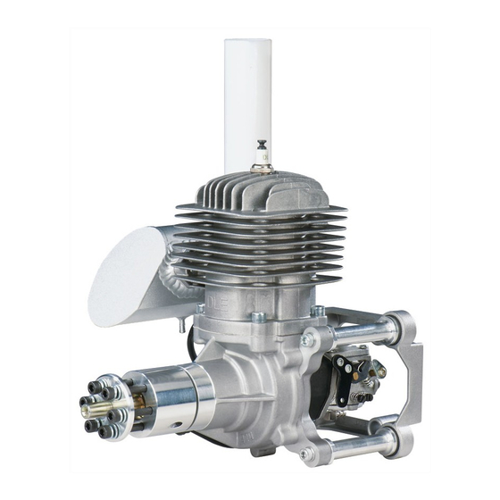
DLE - 85
Operator's Manual
Specifications
Recommended Propellers:
1
© 2014 Hobbico
Displacement:
Performance:
Idle Speed:
Ignition Style:
Sparkplug Type:
Diameter × Stroke:
Compression Ratio:
Carburetor:
Weight:
™
Fuel:
®
, Inc.
84.88cc 5.18 cu in
8.5HP/7,500 RPM
1,500RPM
Electronic Ignition
25×10, 26×9, 27×8
NGK CM6
(Gap) 0.018in.– 0.020 in. [0.45mm – 0.51mm]
2.05in(52mm) × 1.57in(40mm)
9.5: 1
DLE with Manual Choke
Main Engine – 68oz [1930g]
Muffler – 8.8oz [250g]
Electronic Ignition – 4.58oz [110g]
Engine Mount Standoffs – 28oz [454g]
87− 93 Octane Gasoline with a 30:1
gas/2-stroke (2-cycle) oil mixture
DLEG0085 Mnl
Advertisement
Table of Contents

Related Manuals for DLE DLE-85


Summary of Contents for DLE DLE-85
-
Page 1: Specifications
(Gap) 0.018in.– 0.020 in. [0.45mm – 0.51mm] Diameter × Stroke: 2.05in(52mm) × 1.57in(40mm) Compression Ratio: 9.5: 1 Carburetor: DLE with Manual Choke Weight: Main Engine – 68oz [1930g] Muffler – 8.8oz [250g] Electronic Ignition – 4.58oz [110g] Engine Mount Standoffs – 28oz [454g] ™... -
Page 2: Parts List
Safety Tips and Warnings ● This engine is not a toy. Please place your safety and the safety of others paramount while operating. DLE will not be held responsible for any safety issues or accidents involving this engine. ● Operate the engine in a properly ventilated area. - Page 3 ● During the break-in period, it is recommended that the engine be installed on the aircraft or a test stand with an appropriate shock absorber. Otherwise it is probable that vibration could rebound back to the engine and serious damages may occur during the break-in period.
- Page 4 Keep the surface of the engine clean to ensure proper heat dissipation. ● To avoid permanent damage to the electronic ignition system, NEVER rotate the propeller on your DLE engine with the electronic ignition system switched on and the plug not installed in the plug cap.
-
Page 5: Installation Instructions
Installation Instructions Prepare the engine for installation 1. Check to see that all screws and bolts are tight. Check carefully for any cracks, broken, or missing parts. Tighten or replace any damaged or missing parts before proceeding. 2. Install the silicone wire cover over the pick up lead coming from the engine (cut the excess silicone wire cover) and connect the lead to the pick–up lead from the Electronic Ignition Module. - Page 6 4. Connect the ignition module battery to the kill switch. Any 4.8-8.4 V, 1000 mAh and above capacity battery will work well for this. Use heat shrink tubing to secure this connection. Optional: Install the TX activated gas engine kill switch (DLEG9205) between the manual on/off switch and the ignition as shown above.
- Page 7 Use triangle stock and pin the fi rewall with hardwood dowels to reinforce the fi rewall glue joints. Never install the DLE-85 onto a fi rewall thinner than specifi ed because it may fail due to the power of the engine.
- Page 8 5. Install the standoffs to the mount by inserting (4) 5x25mm SHCS and (4) 5x19mm fl at washers through the backside isolation mount. Mount the engine standoffs and isolation mount to the fi rewall by installing the (4) 5x25mm SHCS through the isolation mount and into the fi...
- Page 9 4. Install the manual on/off switch on the aircraft so that it is easily accessible from outside the plane. 5. Install the throttle servo at least 305mm [12"] away from the engine. Make sure that you get the carburetor’s full range of rotation with your servo travel.
- Page 10 Drill and Install the Propeller The easiest way to drill the propeller to fi t the hub is to use a DLE drill guide (DLEQ1111). If you do not have a drill guide, you can use the following method to drill your propellers.
- Page 11 4. Place the propeller on the crankshaft at the one o’clock position. 5. Mark the location of one of the outer holes. Use a GPM Dead Center H o l e L o c a t o r (GPMR8130) to center and start the hole.
-
Page 12: Starting Procedures
There are two recommended ways to start the DLE-85: A. Manual Starting Note: When hand starting the DLE-85, use a thick glove or heavy duty starter stick to protect your hand. 1. The propeller should be installed on the drive washer so that it is at the one o’clock position and at the beginning of the compression... - Page 13 B. Electric Starter Starting 1. A 24 volt electric starter is recommended to start the DLE-85. Make sure you use a high quality, lightweight aluminum spinner. 2. Have someone help you hold the airplane while you start it. 3. Close the choke on the carburetor and open the throttle slightly from the idle position.
-
Page 14: Engine Troubleshooting
Engine Troubleshooting If your engine fails to start after the preceding starting procedures please check the following. Symptom Diagnosis Ignition battery low Charge or replace battery Battery wires faulty Replace wires or Re-connect/check connections Engine does not fire Faulty or fouled Replace spark plug spark plug or not or check for spark *... -
Page 15: Idle Adjustment
Adjustment of the Engine Each DLE Engine has been factory preset. However, elevation changes will infl uence the performance of the carburetor. To obtain optimum output of the engine, slight adjustment of the carburetor maybe necessary. Also, for safety reasons do not make adjustments to the carburetor while the engine is running. -
Page 16: Ignition Timing Adjustment
Smooth acceleration and deceleration is an indicator of proper engine performance. Ignition Timing Adjustment The ignition timing is preset on the DLE-85 at 44° before Top Dead Center (TDC). The ignition timing can be advanced or retarded by loosening the (2) ignition sensor phillips head screws and sliding the sensor to the full extent clockwise (45°... - Page 17 Problem 1. Engine stops at full throttle. 2. Engine hesitates when accelerated rapidly. 3. The engine will not come up to full rpm at full throttle. Solution The high-speed needle valve “H” is too lean. Open it 1/8 of a turn and try again.
-
Page 18: Engine Maintenance
Engine RPMs. Do not install or uninstall the Digital Tachometer while the engine is running. Many of the DLE Ignition modules have an addition lead to plug into the optional tachometer. If your ignition module does not have this additional lead, the digital tachometer can still be used. Simply used the included Y-harness (included with the Digital Tachometer) to connect to the pick-up lead from the engine. - Page 20 Warranty Information The DLE-85 has a two year limited warranty through Hobby Services beginning at date of purchase. Contact Us Hobby Services 3002 N. Apollo Drive Suite #1 Ph: 217-398-0007 Champaign, Il 61822 Fax: 217-398-7721 E-mail: hobbyservices@hobbico.com Web address: www.hobbyservices.com 5.51 in.
- Page 21 Notes...
-
Page 23: Replacement Parts
Replacement Parts Stock Stock Description DLEG8501 85-R1 Prop Washer DLEG8502 85-R2 Prop Drive Hub Nut DLEG8503 85-R3 Prop Drive Hub DLEG8504 85-R4 Bearing Front DLEG8505 85-R5 Crankcase DLEG8506 85-R6 Rubber Gasket DLEG8507 85-R7 Bearing Rear DLEG8508 85-R8 Woodruff Key DLEG8509 85-R9 Crankshaft DLEG8510... - Page 24 DLE-85 Mounting Pattern (for anti-vibration mount) 2.56 in. [65 mm] 2.56 in. [65 mm]...
Need help?
Do you have a question about the DLE-85 and is the answer not in the manual?
Questions and answers