Drazice OKH 100 NTR/HV Operation And Installation Manual
Storage tanks
Hide thumbs
Also See for OKH 100 NTR/HV:
- Operating and installation manual (17 pages) ,
- Operation and installation manual (12 pages)
Table of Contents
Advertisement
Quick Links
Advertisement
Table of Contents

Related Manuals for Drazice OKH 100 NTR/HV


Summary of Contents for Drazice OKH 100 NTR/HV
-
Page 1: Installation Manual
OPERATION AND INSTALLATION MANUAL STORAGE TANKS OKH 100 NTR/HV OKH 100 NTR OKH 125 NTR/HV OKH 125 NTR OKH 160 NTR Družstevní závody Dražice - strojírna s.r.o. Dražice 69, 294 71 Benátky nad Jizerou tel.: +420 / 326 370 990 fax: +420 / 326 370 980 e-mail: prodej@dzd.cz... -
Page 2: Table Of Contents
CONTENTS PRODUCT TECHNICAL SPECIFICATION ....................... 4 FUNCTION DESCRIPTION ........................4 ADVICE FOR CUSTOMERS ........................4 1.2.1 HOT WATER CONSUMPTION ..................... 4 1.2.2 ENERGY SAVING ......................... 4 DESIGN AND GENERAL DIMENSIONS ....................5 OPERATION AND FITTING INSTRUCTIONS ....................8 OPERATING CONDITIONS ........................8 PLUMBING FIXTURE ........................... - Page 3 CAREFULLY READ THIS MANUAL BEFORE INSTALLING THE STORAGE TANK! Dear Customer, The Works Cooperative of Dražice - Machine Plant, Ltd., would like to thank you for your decision to use a product of our brand. With this guide, we will introduce you to the use, construction, maintenance and other information on electrical storage tanks.
-
Page 4: Product Technical Specification
1 PRODUCT TECHNICAL SPECIFICATION 1.1 FUNCTION DESCRIPTION Storage tanks of NTR and NTR/HV series are used for hot service water preparation in conjunction with another source of heating water, most often a gas boiler. Their nominal performance provides sufficient amount of hot water for large flat units, premises, restaurants, and similar establishments. In case of increased hot water consumption, these tanks heat water continuously, operating similarly to flow heaters. -
Page 5: Design And General Dimensions
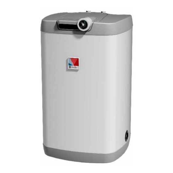
8 Circulation 9 Mg anode 10 Hot water drain pipe 11 Electric installation cover Figure 1 Technical desription: OKH 100 NTR/HV, OKH 125 NTR/HV 1 Thermometer 2 Enamelled steel receptacle 3 Storage tank shell 4 Polyurethane freon-free insulation 5 Tubular heat exchanger... - Page 6 1047 1232 *Height from the bottom heater's edge to the end of the water inlet and outlet Figure 3 tubes. OKH 100 NTR/HV, OKH 125 NTR/HV OKH 100 NTR/HV OKH 125 NTR/HV 1052 1047 *Height from the bottom heater's edge to the end of the water inlet and outlet tubes.
- Page 7 SPECIFICATIONS OKH 100 OKH 125 OKH 160 OKH 100 OKH 125 TYPE NTR/HV NTR/HV VOLUME MAX WEIGHT WITHOUT WATER HEAT TRANSFER 1,08 1,45 1,45 1,08 1,45 SURFACE MAX. TANK PRESSURE MAX. PRESSURE OF EXCHANGER MAX. TEMPERATURE °C OF HSW RECOMMENDED HSW °C TEMPERATURE HSW CONNECTION...
-
Page 8: Operation And Fitting Instructions
2 OPERATION AND FITTING INSTRUCTIONS 2.1 OPERATING CONDITIONS The tank shall only be used in accordance with the conditions specified on the performance plate and in instructions for electric wiring. Besides legally acknowledged national regulations and standards, also conditions for connection defined in local electric and water works have to be adhered to, as well as the installation and operation manual. - Page 9 It is necessary to check the safety valve each time before putting it into operation. It is checked by manual moving of the membrane from the seat, turning the make-and-break device button always in the direction of the arrow. After being turned, the button must click back into a notch.
-
Page 10: Electric Wiring
2.3 ELECTRIC WIRING 2.3.1 ELECTRIC INSTALLATION GENERAL INFORMATION Check the insertion of the thermostat sensor in the thermowell, the so-called insertion all the way. The storage tank can be connected to any hot water heating boiler up to the power output of 50 kW. -
Page 11: Connection Of Storage Tank To Hot Water Heating System
2.4 CONNECTION OF STORAGE TANK TO HOT WATER HEATING SYSTEM It is recommended to install stop valves on the heating water inlet and outlet (for possible dismantling of the storage tank). The valves have to be as close to the storage tank as possible to avoid higher thermal losses The heating circuit is connected to marked inputs and outputs of the storage tank exchanger;... -
Page 12: First Commissioning
2.5 FIRST COMMISSIONING After connecting the storage tank to the water supply, the hot water heating system, the electric network, and after testing its safety valve (based on the valve manual attached), the storage tank may be put into operation. Before opening the power supply, the tank must be filled with water. -
Page 13: Inspection, Maintenance & Care For The Appliance
2.7 INSPECTION, MAINTENANCE & CARE FOR THE APPLIANCE During the heating process the water that increases its volume during the heating must drip off the safety valve outlet (in non-pressurised connection this water drips off the combination faucet valve). In full heating (about 65 C) the volumetric water gain is approx. -
Page 14: Most Frequent Function Failures And Their Causes
2.8 MOST FREQUENT FUNCTION FAILURES AND THEIR CAUSES FAILURE SYMPTOM SOLUTION Water is constantly LED is not on input pressure is too high dripping off the safety faulty safety valve valve Table 3 Do not try to repair the failure yourselves. Seek either expert or service help. It does not take much for an expert to remove the defect. -
Page 15: Temperature Setting
3.1.2 TEMPERATURE SETTING Water temperature is set by turning the thermostat knob. The desired symbol is adjusted against the fixed point on the control panel (Figure 9). „Ideal“ temperature (about Upper temperature range 55°C) (about 80°C) Lower temperature range (about 5°C) „Anti-freezing“... -
Page 16: Product Accessories
Both the electric and water installation must follow and meet the requirements and regulations relevant in the country of use! Please note that the storage tank can't be switched on at the mains when working in the vicinity of flammable liquids (petrol, spot remover) or gases, etc.. 4.2 PRODUCT ACCESSORIES G3/4"...
Need help?
Do you have a question about the OKH 100 NTR/HV and is the answer not in the manual?
Questions and answers