Drazice OKC 80 Operation And Installation Manual
Tank-type water heaters for vertical mounting
Hide thumbs
Also See for OKC 80:
- Operation and installation manual (21 pages) ,
- Operating and installation manual (20 pages) ,
- Operating and installation manual (23 pages)
Table of Contents
Advertisement
Quick Links
OPERATION AND
INSTALLATION MANUAL
TANK-TYPE WATER HEATERS FOR VERTICAL
Družstevní závody Dražice - strojírna s.r.o.
Dražice 69, 294 71 Benátky nad Jizerou
tel.: +420 / 326 370 990
fax: +420 / 326 370 980
e-mail: prodej@dzd.cz
MOUNTING
Combined water heather
OKC 80
OKC 100
OKC 125
OKC 160
OKC 180
OKC 200
2
OKC 100/1 m
2
OKC 125/1 m
2
OKC 160/1 m
2
OKC 180/1 m
2
OKC 200/1 m
Advertisement
Table of Contents

Related Manuals for Drazice OKC 80


Summary of Contents for Drazice OKC 80
-
Page 1: Installation Manual
OPERATION AND INSTALLATION MANUAL TANK-TYPE WATER HEATERS FOR VERTICAL MOUNTING Combined water heather OKC 80 OKC 100 OKC 100/1 m OKC 125 OKC 125/1 m OKC 160 OKC 160/1 m OKC 180 OKC 180/1 m OKC 200 OKC 200/1 m Družstevní... -
Page 2: Table Of Contents
CONTENTS PRODUCT TECHNICAL SPECIFICATION ....................... 4 FUNCTION DESCRIPTION ........................4 ADVICE FOR CUSTOMERS ........................4 1.2.1 HOT WATER CONSUMPTION ..................... 4 1.2.2 ENERGY SAVING ......................... 4 DESIGN AND GENERAL HEATER DIMENSIONS ................... 5 OPERATION AND FITTING INSTRUCTIONS ....................8 OPERATING CONDITIONS ........................8 WALL MOUNTING .......................... - Page 3 READ CAREFULLY THE BELOW INSTRUCTIONS PRIOR TO THE INSTALLATION THE HEATER! Dear Customer, The Works Cooperative of Dražice – Machine Plant, Ltd., would like to thank you for your decision to use a product of our brand. With this guide, we will introduce you to the use, construction, maintenance and other information on electrical water heaters.
-
Page 4: Product Technical Specification
1 PRODUCT TECHNICAL SPECIFICATION 1.1 FUNCTION DESCRIPTION The heater is designed for accumulation heating of service water using electricity or thermal energy via an exchanger. Water is heated by an electric element or a heat exchanger in an enamelled thermally insulated accumulator at the time defined by the power supplier. -
Page 5: Design And General Heater Dimensions
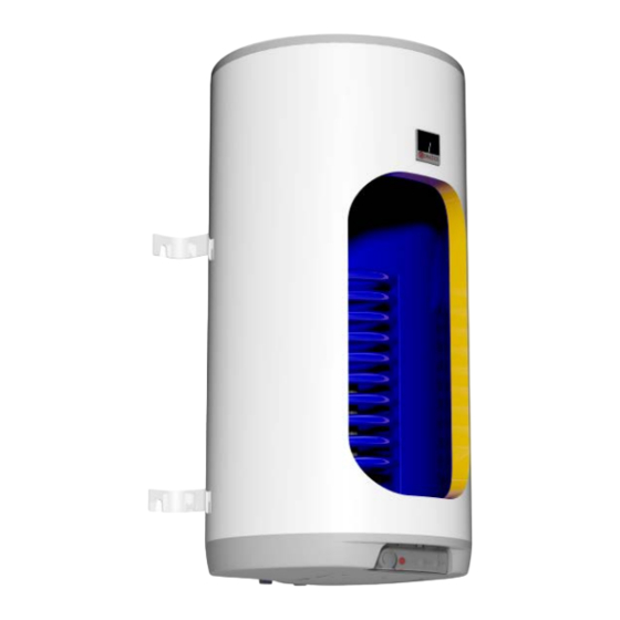
ELECTRICICTY CONSUMPTION FOR NOMINAL CAPACITY TIME OF CONTENT HEATING HEATER TYPE HEATING THE VOLUME (HOURS) FROM 15°C TO 65°C IN OKC 80 OKC 100; OKC 100/1 m OKC 125; OKC 125/1 m OKC 160; OKC 160/1 m OKC 180; 10,6 OKC 180/1 m OKC 200;... - Page 6 Technical description: OKC 80, OKC 100, OKC 125, OKC 160, OKC 180, OKC 200, OKC 100/1m , OKC 125/1m , OKC 160/1m , OKC 180/1m , OKC 200/1m Upper lower suspension Upper suspension 160,180,200L and support 4 anchor bolts 80-125L...
- Page 7 OKC 80 OKC 100 OKC 125 OKC 160 OKC 180 OKC 200 TYPE OKC 100/1 m OKC 125/1 m OKC 160/1 m OKC 180/1 m OKC 200/1 m VOLUME MAX OPERATING OVERPRESSURE IN THE TANK MAX MAXIMUM OPERATING OVERPRESSURE IN THE...
-
Page 8: Operation And Fitting Instructions
2 OPERATION AND FITTING INSTRUCTIONS 2.1 OPERATING CONDITIONS The tank shall only be used in accordance with the conditions specified on the performance plate and in instructions for electric wiring. Besides legally acknowledged national regulations and standards, also conditions for connection defined in local electric and water works have to be adhered to, as well as the installation and operation manual. -
Page 9: Plumbing Fixture
Figure 2 2.3 PLUMBING FIXTURE Connection of heaters to plumbing fixtures is illustrated on (figure 4, figure 6). For potential disconnection of the heater, the service water inlets and outlets must be provided with screw coupling Js 3/4“. The safety valve is mounted on the cold water inlet identified with a blue ring. - Page 10 system. No stop valves can be put between the heater and the safety valve. During assembly, follow the guide provided by the safety equipment manufacturer. It is necessary to check the safety valve each time before putting it into operation. It is checked by manual moving of the membrane from the seat, turning the make-and-break device button always in the direction of the arrow.
-
Page 11: Electric Installation
2.4 ELECTRIC INSTALLATION 2.4.1 ELECTRIC INSTALLATION GENERAL INFORMATION • The electric wiring scheme is attached to the water heater on the side of the electric installation guard (figure 4). • Connection, repairs, and wiring inspections may only be implemented by a company (person) authorised to such activity. - Page 12 the stop valve on the inlet to the exchanger has to be closed, which prevents heating water in the hot water heating system. b) Service water heating via thermal energy through heat exchanger Closing valves of the heat exchanger must be opened which ensures heating water flow from the hot water heating system.
-
Page 13: First Heater Commissioning
2.6 FIRST HEATER COMMISSIONING After connecting the heater to the water supply, the hot water heating system, the electric network, and after testing its safety valve (based on the valve manual attached), the heater may be put into operation. Before opening the power supply, the tank must be filled with water. -
Page 14: Inspection, Maintenance & Care For The Appliance
entire cold water supply piping. It is therefore advisable to drain all fittings and piping that carry water, up to the part where the house water meter is installed (connection of the house to water main) which is not jeopardised by frost. When the tank is to be used again, it has to be filled with water and one needs to make sure that the water flowing out at the hot water valves did not contain any bubbles. -
Page 15: Most Frequent Function Failures And Their Causes
2.9 MOST FREQUENT FUNCTION FAILURES AND THEIR CAUSES Další možné poruchy -Table 6. FAILURE SYMPTOM INDICATOR SOLUTION Water is cold • • Light on The temperature set on the thermostat is too low • • Light off Heating element failure •... -
Page 16: Operation Of Thermostat
3 OPERATION OF THERMOSTAT 3.1 SERVICING 3.1.1 OPERATING DEVICES OF THE HEATER Operating devices of heaters of 50 to 200 l capacity are located under the transparent guard of the control panel. Thermostat knob Electric circuit closing indicator lamp Tipping plastic guard Figure 6 3.1.2 TEMPERATURE SETTING Water temperature is set by turning the thermostat knob. -
Page 17: Important Notices
4 IMPORTANT NOTICES 4.1 INSTALLATION REGULATIONS Without a confirmation of performed electrical installation issued by an authorised company, the warranty certificate shall be void. Check and exchange the Mg anode regularly. You have to apply for approval of a local power supplier to connect the heater. No stop valves can be put between the heater and the safety valve. -
Page 18: Product Accessories
5 PRODUCT ACCESSORIES The product is supplied with a safety valve, 2 – 4 fastening screws M 12x30, 2-4 washers φ 13 brackets), and a thermometer. The above parts are packed and placed in the packaging in the top part of the heater. It is in your own interest to check the completeness of the accessories.
Need help?
Do you have a question about the OKC 80 and is the answer not in the manual?
Questions and answers