Table of Contents
Advertisement
Quick Links
Advertisement
Table of Contents

Subscribe to Our Youtube Channel
Related Manuals for Koden ESR-140Mk II


Summary of Contents for Koden ESR-140Mk II
-
Page 2: Declaration Of Conformity
Declaration of Conformity (As required by Article 7 (1) of Directive 89/336/EEC) Declares under his sole responsibility that the produced Color Sonar manufactured by Koden Electronics Co., Ltd. 5278 Uenohara Uenohara-Shi Yamanashi-Ken 409-0112, Japan Telephone +81 554 20 5865 Telefax +81 554 20 5880 ESR-140MkⅡ... - Page 3 No part of this publication may be reproduced, transmitted, translated in any form by any means without the written permission of Koden Electronics Co., Ltd. The technical descriptions contained in this publication are subject to change without notice. Koden assumes no responsibility for any errors, incidentals or consequential damages caused by misinterpretation of the descriptions contained in this publication.
- Page 4 INTRODUCTION Thank you for purchasing the ESR-140 MkⅡSearchlight Sonar. We are confident you will enjoy using your unit for many years to come. This manual provides complete information on safely operating the ESR-140 MkⅡ. Please carefully read and follow the safety information so that the ESR-140 MkⅡ will perform to the utmost of its ability.
-
Page 5: Safety Instruction
SAFETY INSTRUCTION SYMBOLS The following symbols are used in this manual. Please read this manual carefully and take note of these symbols. indicates an imminently hazardous situation which, if not avoided, DANGER will result in death or serious injury. indicates a potentially hazardous situation which, if not avoided, WARNING could result in death or serious injury. -
Page 6: For Your Safety
FOR YOUR SAFETY INSTALLATION SITE REQUIREMENTS Keep the unit away from the flammable gas. WARNING Otherwise it causes a fire. Follow the below proposed conditions for the installation. CAUTION Otherwise it cases a fire or an electrical shock. Away as much as possible from areas where the unit is likely to be exposed to direct water spray and free as much as possible from shocks and engine vibration. - Page 7 FOR YOUR SAFETY HANDLING Do not operate the unit while steering. DANGER Otherwise it will cause wrecks. Do not open the case cover. There is a risk of electrical shock if you touch the high voltage conductors. Only qualified personnel should work inside the unit. Care for sufficient reinforcement and being watertight should be taken when installing the hoist.
-
Page 8: Table Of Contents
CONTENTS INTRODUCTION………………………………………………………………….……. SAFETY INSTRUCTION……………………………………………………………… FOR YOUR SAFETY………………………………………………………………….. CONTENTS…………………………………………………………………………….. COMPONENTS…………….………………………………………………………….. CHAPTER 1 SONAR SYSTEM SUMMARY……………………………... 1 - 1 1 - 2 Sonar Mode……………………………………………………… 1 - 4 Tilt Angle…………………………………………………………. 1 - 5 Tilt Angle and Display…………...…………………………….. 1 - 6 Bottom Scan Mode…………………………………………….. 1 - 7 Echo Sounder Mode……………………………………………... - Page 9 3 - 5 Function settings……………………………………………………………………. 3 - 6 Setting Functions Gain Up…………………………………….. 3 - 7 TVG Curve…………………….…..……….. 3 - 7 Dynamic Range……………….….……….. 3 - 8 Pulse Width………………….…….………. 3 - 8 TX Power……………………….…….……. 3 - 9 Reduction Interference Reduction……..…………….. 3 - 9 Noise Reduction…….………………….….
-
Page 10: Components
COMPONENTS COMPONENTS - ** VM110 ** VM030 CODE POWER SUPPLY KNOB DISPLAY CABINET COVER CABLE DISPLAY UNIT BRACKET BOLT PART 2m P./No ESR-1401 A30MB10411 CW-206-2M A30MB10370.1 A30MB10250 1 1 1 2 1 ** VM121 CODE OPERATION FUSE MANUAL PART 6 A 8... - Page 11 COMPONENTS ** VN120 ** VN110 GASKET BOLT SET ×4 PART ×4 ×8 ×4 35612D M20×80 Assy P./No 1 1 - ** VN140 CODE FASTENING LOCK NUT BAND JOINT PIPE DAMPER 2 PIPE CAP PART 35608C 35609D 35611D SD-2050 35624D P./No 1...
-
Page 12: Sonar System Summary
CHAPTER 1 SONAR SYSTEM SUMMARY This chapter provides some basic information of the PPI (Plan Position Indicator) searchlight sonar. SONAR MODE 1 - 2 ……………………………………………………... TILT ANGLE 1 - 4 ………………………………………………………… TILT ANGLE AND DISPLAY 1 - 5 ………………..….………………. BOTTOM SCAN MODE. 1 - 6 ……………………………….……….. -
Page 13: Sonar Mode
SONAR SYSTEM SUMMARY SONAR MODE A sonar system uses the transmitter-receiver as well as an echo sounder. An echo sounder is only able to search in one direction, down. However a sonar has a movable transducer and therefore can freely search the entire around a ship, not just the area directly beneath the ship. - Page 14 SONAR SYSTEM SUMMARY An echo sounder is only able to search in one direction within some beam angle, beneath the ship. A sonar, however, can freely search the broad range, since the transducer’s angle can be varied not only the horizontal direction but also the vertical direction. SONAR DISPLAY RANGE ECHO SOUNDER DISPLAY RANGE HORIZONTAL ANGLE (SECTOR) 180°...
-
Page 15: Tilt Angle
SONAR SYSTEM SUMMARY TILT ANGLE The tilt angle shows the direction to which the sound 5゜ wave is emitted. The tilt angle can be set in step of 1° 0゜ from 0° to +5° (upward) to 0° to 90° (downward). TILT ANGLE Find out the suitable tilt angle for a given depth and SETTING RANGE... -
Page 16: Tilt Angle And Display
SONAR SYSTEM SUMMARY TILT ANGLE AND DISPLAY In the shallow water the bottom reflection is prominent, so it is important to be able to distinguish fish echoes from the bottom echo. Therefore the setting of the tilt angle is important to find out the suitable tilt angle. ③... -
Page 17: Bottom Scan Mode
SONAR SYSTEM SUMMARY BOTTOM SCAN MODE OWN SHIP POSITION When this mode is selected, the transmitter/ receiver does not rotate like a sonar, but sweeps from side to side like a pendulum FISH when the sound wave is emitted. The reflected echo from the sea SCHOOL bottom is displayed on the screen sequentially. -
Page 18: Echo Sounder Mode
SONAR SYSTEM SUMMARY ECHO SOUNDER MODE The transmitter/receiver faces the sea bottom, and emits the ultra-sound beam. The reflected ECHO SOUNDER DISPLAY echo from the sea bottom is displayed on the screen. The image is displayed like a usual echo sounder. DETECTS DIRECTLY UNDER THE SHIP CHENGES THE TILT ANGLE The tilt angle and the direction can be changed. -
Page 19: Sample Display Of Sonar Mode
SONAR SYSTEM SUMMARY SAMPLE DISPLAY OF SONAR MODE COMPASS DISP. R A N G E COLOR SCALE 160m B E A R I N G S 0゜ SEA BOTTOM OPERATION W S E C T O R CROSS CURSOR MODE 360゜... -
Page 20: Sample Display Of Echo Sounder Mode
SONAR SYSTEM SUMMARY SAMPLE DISPLAY OF ECHO SOUNDER MODE DIRECTION SURFACE TIME MARKER R A N G E 160m TILT ANGLE B E A R I N G 0゜ OPERATION S E C T O R ---゜ MODE T I L T -60゜... -
Page 21: Sonar Operation
Chapter 2 SONAR OPERATION This chapter provides you the description of operation dials and keys for the ESR-140MkⅡ Sonar OPERATION PANEL…………………………………………………… 2 - 2 OPERATION KEYS Power On/Off Key………………..……………………………….. 2 - 3 Sensor Lamp……………………………………………………….. 2 - 3 Hoist Keys………………………………...………………………... 2 - 3 Sonar Mode key……………………………………………………. -
Page 22: Operation Panel
OPERATION PANEL 6 5 4 6 3 7 1 2 8 1 9 0 1 0 ON 2 5 4 6 3 7 2 8 1 2 3 OFF 1 9 0 1 0 4 5 7 8 9 NAME ACTION SENSOR LAMP The Sensor Lamp lights while the soundome is... -
Page 23: Operation Keys
OPERATION KEYS POWER ON/OFF KEY To turn on the power, press [ON] key. When power is applied, the Soundome lowers automatically and the following will occur. The sensor lamp is lighted on. The sensor lamp mark appears on the down left corner of the screen. The sign “WAITING”... -
Page 24: Sonar Mode Key
OPERATION KEYS SONAR MODE KEY Displays the Sonar Mode. Tilt angle is adjusted by the Tilt keys. RANGE BEARING page 2-6 SECTOR TILT MARKER Sector angle is adjusted by the + CURSOR Sector keys. SHIP’S POSITION page 2-8 The scanning direction is adjusted by the Bearing keys. -
Page 25: Bearing Keys
OPERATION KEYS BEARING KEYS Use these keys to define the center of current scanning sector in the Sonar Mode. The bearing angle of the display is shifted with every 5° steps. Displays the center of Rotates the center of Rotates the center of the sector angle. -
Page 26: Tilt Keys
OPERATION KEYS TILT KEYS Use these keys to control the tilt angle in the Sonar Mode. The tilt angle can be set in increments of 1° from 0° to 5° (upward) to 0° to 90° (downward). 5゜ 0゜ Changes this angle. RANGE BEARING SECTOR... - Page 27 OPERATION KEYS Use these keys to control the tilt angle in the Echo Sounder Mode. The tilt angle can be set in increments of 1° from 0° to 5° (upward) to 0° to 90° (downward). TILT DIRECTION RA NG E This angle is adjusted DIRECTION ANGLE BE AR IN G...
-
Page 28: Sector Keys
OPERATION KEYS SECTOR KEYS Changes the sector angle (horizontal angle) in the Sonar Mode. Displays the selected angle. R A NG E B EA RI NG S EC TO R T IL T M AR KE R CU R SO R Changes this angle. -
Page 29: Range Keys
OPERATION KEYS RANGE KEYS Changes the basic range (the basic depth) Displays the selected values and units. RANGE BEARING SECTOR TILT MARKER CURSOR Changes this distance. SCALE MARKER 20 selectable ranges are available. Each press of the Range [ △ ] key makes the range value smaller. -
Page 30: Operation Mode Keys
OPERATION KEYS OPERATION MODE KEYS Use these keys to select one of 2 kinds of operation mode you have created. (You may be able to create 4 kinds of operation mode by FUNCTION SETTINGS. page 3-15) By pressing one of these keys, the desired operation mode can be set immediately. To memorize the setting in the Operation Mode key, the following procedure is required. -
Page 31: Cursor Keys
OPERATION KEYS CURSOR KEYS By using these keys, the horizontal range, depth and bearing to the target can be measured. Use [Cursor Selection] key to select a cursor and [ ↑ ↓ ← → ] keys move the cursor in any direction on the screen. - Page 32 OPERATION KEYS When the Ring Marker is selected (the Cross Cursor is in red or not displayed,) SONAR MODE :HORIZONTAL DISTANCE (“a” in the below drawing) :SLANT DISTANCE (“b” in the below drawing) MARKER :DEPTH (“c” in the below drawing) This key lengthens the distance.
-
Page 33: Target Lock Key
OPERATION KEYS TARGET LOCK KEY When pressing the Target Lock key in the Sonar Mode, the direction of sweep of the sonar beam is reversed. (When MENU / TARGET LOCK / MODE 0 is selected.) When pressing the Target Lock key in the Sonar Mode, the sonar beam tracks the echo automatically. -
Page 34: Menu Key
OPERATION KEYS MENU KEY Use this key to set the basic functions. Pressing this key displays MAIN MENU M A I N M E N U on the right of the screen. + Refer to Chapter 3 “FUNCTION SETTINGS” for more details. By pressing this key again, MAIN MENU disappears. -
Page 35: Operation Dials Brightness Dial
OPERATION DIALS BRIGHTNESS DIAL Turn this dial clockwise to increase the screen brightness and “10” is 5 4 6 the brightest. 3 7 2 8 1 9 0 1 0 GAIN DIAL Adjusts the sensitivity of the received signal and turn this dial 5... -
Page 36: Function Settings
Chapter 3 FUNCTION SETTINGS This chapter provides you the main functions of the ESR-140MkⅡ Sonar and describes the primary controls. It also suggests settings to use for initial start up. INITIAL SETTINGS Factory Settings…………………………………………………. 3 - 2 Return to Factory Settings…………………...………………... 3 - 3 User Settings………...………………………………………….. - Page 37 INITIAL SETTINGS FACTORY SETTINGS The ESR-140MkⅡ is shipped from the factory with the functions under the settings listed below. Before using it, please enter the functions to the desired setup. FUNCTIONS FACTORY SETTINGS (in the item □ FUNCTION SET page 3-5 GAIN UP ・...
-
Page 38: Return To Factory Settings
INITIAL SETTINGS RETURN TO FACTORY SETTINGS First press the Power [OFF] key, then press [ON] key while pressing both the Bearing keys [ ← → ] at the same time. Keep pressing the Bearing keys [ ← → ] until the beep sound stops. Activating this operation will erase all settings excluding "Train Correct"... -
Page 39: Menu
MENU FUNCTION SET MENU Basic functions may be briefly described in the following. Before first using the ESR-140MkⅡ, customizing the functions to suit individual needs. The following function items can be customized in the function set menu. MAIN MENU FUNCTION SET :GAIN UP :TVG CURVE :DYNAMIC RANGE... -
Page 40: Function Settings
FUNCTION SETTINGS Press the Menu key to display the menu below. Use the Cursor Shift key [ ↑ ] or [ ↓ ] to highlight the item you wish to change. By pressing the Cursor Shift key [ ← ] or [ →... -
Page 41: Gain Up
FUNCTION SETTINGS 1. GAIN UP This function makes it possible to display a clearer picture of the full range and control the sensitivity at various depths. Each press of [ ← ] or [ → ] key changes the setting, "OFF, +10dB, +20dB, +30dB, +40dB."... -
Page 42: Tvg Curve
FUNCTION SETTINGS 2. TVG CURVE TVG offsets the effects of propagation loss of sound as it passes through the water. Propagation loss of sound is the sum of spreading and attenuation losses. The TVG curve is adjusted to counter the loss. Each press of [ ←... -
Page 43: Pulse Width
FUNCTION SETTINGS 4. PULSE WIDTH The transmitted pulse width can be set. The transmitted pulse can be set to these three (narrow, normal, wide), where the optimum setting will be applied according to the range automatically. Or it can be set manually, if a specific pulse width (0.1 ~... -
Page 44: Noise Reduction
FUNCTION SETTINGS REDUCTION REDUCTION INTERFERENCE RED NOISE REDUCTION Use the Cursor Shift key [ ↑ ] or [ ↓ ] to highlight the item you wish to change. Press [ ← ] or [ → ] key to select the desired setting. -
Page 45: Display Item Selection Step (Sonar)
FUNCTION SETTINGS DISPLAY ITEM SELECTION DISP ITEM SEL. STEP (SONAR) 10° STEP (BOTTOM SCAN) 5° OFF-CENTER POS. FORE Use the Cursor Shift key [ ↑ ] or [ ↓ ] to SCALE DOTS highlight the item you wish to change. COMPASS DISP. -
Page 46: Step (Bottom Scan)
FUNCTION SETTINGS 2. STEP (BOTTOM SCAN) The step angle (scanning angle) in the Bottom Scan Mode may be selected. Each press of [ ← ] or [ → ] key changes the setting, "3° or 5°." Select the desired step angle, and then press the Enter key. 3°... -
Page 47: Scale Display
FUNCTION SETTINGS 4. SCALE DISPLAY The scale dots display under the Sonar Mode can be turned on / off. Each press of [ ← ] or [ → ] key changes the setting, "ON or OFF." Select ON or OFF, and then press the Enter key. When the scale dots display OFF is selected, no scale appears on the screen in the SONAR / OFF-CENTER... -
Page 48: Others Target Lock
FUNCTION SETTINGS OTHERS OTHERS TARGET LOCK MODE 0 OPERATION MODE DEPTH UNIT Use the Cursor Shift key [ ↑ ] or [ ↓ ] to TEMP. UNIT °C highlight the item you wish to change. SPEED UNIT Press [ ← ] or [ →... - Page 49 FUNCTION SETTINGS MODE 1 R A N G E ***m By pressing the Target Lock key, the Sonar beam will track the echo automatically left and right. T A R G ET L O C K "TARGET LOCK" will be displayed at the right of the screen.
-
Page 50: Operation Mode
FUNCTION SETTINGS 2. OPERATION MODE 4 kinds of operation mode can be memorized by switching the function setting number “0” or “1” with the operation mode [1] and [2] keys. Each press of [ ← ] or [ → ] key changes the setting, “0 or 1.” Select the desired function setting number, and then press the Enter key. -
Page 51: Hoist Auto Up
FUNCTION SETTINGS 6. HOIST AUTO UP The Soundome can be retracted automatically when the ship speed is over a specified speed by connecting to an external equipment. Each press of [ ← ] or [ → ] key changes the setting, “OFF, 10kt (18km/h).” Select the desired value, and then press the Enter key. -
Page 52: Color
FUNCTION SETTINGS 8. COLOR The display tone (COLOR BAR) and the background color may be selected as desired from 4 optional patterns, “A-1, A-2, B-1, B-2.” And the tone range may be specified freely on C-1 and C-2 in Color Palette function. (The initial setting of the color tone for C-1 is the same as A-1 and C-2 is the same as B-1.) Each press of [ ←... -
Page 53: Language
FUNCTION SETTINGS 9. LANGUAGE The choice of language Each press of [ ← ] or [ → ] key changes the setting, “English, French, Portugal, Italian, Greek” 3-18... -
Page 54: Installation
Chapter 4 INSTALLATION This chapter explains the installation for sonar monitor and hull unit. INSTALLATION POSITION…………………………...………………. 4 - 2 DIMENSIONS…………………………………………………………… 4 - 3 TRUNK PIPE INSTALLATION 1. Maintenance Space…………………………………………….. 4 - 4 2. Installation Conditions…………………………………………. 4 - 5 HOIST/LOWER UNIT ASSEMBLY 1. - Page 55 INSTALLATION Fully discussion and agreement are required with the ship owner and dockyard in deciding the location for the hull unit. Give careful considerations on mounting. INSTALLATION POSITION Select an area where noise, bubbles and interference from turbulences are minimal. The point at 1/3 to 1/2 of the ship’s length from the bow is the best.
-
Page 56: Dimensions
INSTALLATION DIMENSIONS BOW SIDE HOIST/LOWER UNIT 14 3 11 5 25 8 TRUNK PIPE SUS304TP-S-C STPG38-S-C 100A×Sch40 (φ114.3×t6) φ1 14 .3 φ97 DISPLAY UNIT 4-3... -
Page 57: Trunk Pipe Installation
INSTALLATION TRUNK PIPE INSTALLATION 1. MAINTENANCE SPACE When installing the Trunk Pipe, pay full attention to the safety (strength, water-tightness, etc.). At the same time, secure a space for maintenance and inspections. Since the Hoist unit is not a waterproof structure, keep it away from water drops and splashes. -
Page 58: Installation Conditions
INSTALLATION 2. INSTALLATION CONDITIONS The Trunk Pipe should be installed satisfying the following conditions. The position for installation should be within 1/3 to 1/2 of the overall length from the bow. It also should be on the keel or within 1 meter from the keel. FLANGE HOLE ANGLE There should be no obstacles 9... -
Page 59: Hoist/Lower Unit Assembly
INSTALLATION HOIST/LOWER UNIT ASSEMBLY 1. JOINT PIPE LENGTH Calculate necessary length of joint pipe from the length of Trunk pipe (Lt) and cut off the space portion if the shorter length than the standard 1,240mm is required. TRUNK PIPE LENGTH (Lt)+ 60mm 2. -
Page 60: Mounting Joint Pipe Into Soundome
INSTALLATION 3. MOUNTING JOINT PIPE INTO SOUNDOME When assembling the Joint Pipe into the Soundome, the Soundome must be fixed, and screw the Joint Pipe into the Soundome. Be sure not to damage the Joint Pipe thread or twist the Soundome cable. ①... -
Page 61: Attaching Soundome To Hoist
INSTALLATION 4. ATTACHING SOUNDOME TO HOIST Apply grease to the Flange bearing (figure ① ) where the Joint Pipe is passed through. Pass the Damper (figure ② ) through and mount it into the Joint Arm(figure ③ ) facing the bow mark toward ship’s bow. -
Page 62: Hoist/Lower Unit And Trunk Pipe Attachment
INSTALLATION 5. HOIST/LOWER UNIT AND TRUNK PIPE ATTACHMENT Use 4 Hexagonal Bolts (M20x80) to fit the Hoist/Lower Unit to the Trunk Pipe. Make tentative clamp and try to move the Soundome up and down for several times to confirm the alignment when making the final clamping evenly. The Hoist can be operated manually. -
Page 63: Adjustment Of Hoist Stroke
INSTALLATION ADJUSTMENT OF HOIST STROKE The stroke can be adjusted from 120mm at the minimum to the 200mm at the maximum by changing the position of the Limit Switches. Turn off the power for the motor before adjusting the Limit Switches. -
Page 64: Manual Raise/Lower Of Soundome
INSTALLATION MANUAL RAISE/LOWER OF SOUNDOME The Soundome can be raised or lowered manually when mounting the Hoist and the Trunk Pipe or adjusting the stroke. The manual operation is also available in case of a trouble that the Soundome can not be raised or lowered automatically. -
Page 65: Mounting Method Of Display Unit
INSTALLATION MOUNTING METHOD OF DISPLAY UNIT ① Fasten the Bracket to the place you selected with 4 tapping screws. ② Screw the Knob Bolts to the hole on both sides of the Display Unit. ③ Insert the Display Unit into the Bracket. ④... -
Page 66: Connections
INSTALLATION CONNECTIONS Prior to the connections between the Display Unit and the Hull Unit, read the following warning carefully to ensure its correct operation. WARNING Operating voltage: 20 to 30 volts DC Use the correct voltage, otherwise it will result in fire or electrical shock. Use the specified power supply cables. -
Page 67: Electrical Connections - Terminals
INSTALLATION ELECTRICAL CONNECTIONS - TERMINALS Explanation of the Terminals on the rear of the Display Unit TRIGGER OUTPUT TERMINAL NAV-IN TERMINAL LIMIT SWITCH TERMINAL 1 5 1 3 1 7 8 4 2 2 6 2 3 4 3 5 1: UPPER LIMIT SWITCH 1: TRIGGER OUTPUT + 1: SIGNAL INPUT +... - Page 68 INSTALLAT AUDIO TERMINAL REMOTE CONTROL TERMINAL 1 5 1 4 2 2 5 4 3 3 Audio Box Remote controller OP-603 OP-1609 MONITOR TERMINAL 1:RVD 2:GVD 3:BVD 4:NC 5:GND 6:R-GND 7:G-GND 8:B-GND 9:NC 10:GND 11:NC 12:NC 13:H-SYNC 14:V-SYNC 15:NC 4-15...
-
Page 69: Chapter 5 Option
Chapter 5 OPTION This chapter provides you the explanation related to the optional kits. OPTION…………………………...…………………………………… 5 - 2 REMOTE CONTROLLER…………………………………………… 5 - 2 5-1... -
Page 70: Remote Controller
OPTION OPTION The ESR-140MkⅡ is designed to interface with the remote controller or the VGA output or the Audio output. (*optional kit is required) Parts No. NAME MEMO OP-1609 Remote Controller the cable included OP-603 Audio Box the audio cable included the audio plug included OP-603 does not include an audio speaker (4 ohm) and a speaker cable. - Page 71 OPTION REMOTE CONTROLLER SETTING 1. Press MENU KEY. “MENU” appears on the screen. 2. Use the cursor shift key 「↑」 「↓」 to highlight “REMOTE CONTROLLER SET” and by pressing the cursor shift key 「←」 「→」 the following appears on the screen. Use the cursor shift key 「↑」...
-
Page 72: Appendix
Chapter 6 APPENDIX This chapter describes you the daily maintenance, disposal, and specifications of the ESR-140MkⅡ Sonar. It also provides a memo of operation mode. DAILY MAINTENANCE……………………………………………… 6 - 2 DISPOSAL…………………………………………………………….. 6 - 3 SPECIFICATIONS……………………………………………………. 6 - 4 MEMO OF OPERATION MODE……………………………………. 6 - 5 6-1... -
Page 73: Daily Maintenance
LCD display lightly with an absorbent cotton or clean soft cloth after removing the filter. If there is dust you can not wipe away, contact your local dealer or KODEN head office. APPLYING GREASE Apply grease regularly to the Hoist Gears (figure A) and the Flange Opening (figure B). -
Page 74: Disposal
DISPOSAL WARNING This equipment contains the lithium battery of high-density energy. Careless disposal of the lithium battery causes electric shorts, impact, generation of heat, electrical shock, explosion, injury, or fire. DISPOSAL of EQUIPMENT Dispose of this equipment in accordance with local regulations. DISPOSAL of LITHIUM BATTERY Before disposing of the lithium battery, place a piece of adhesive tape across the plus and minus terminals as non-combustible garbage. -
Page 75: Specifications
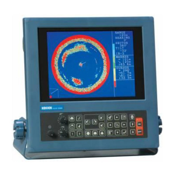
SPECIFICATIONS DISPLAY Display 10.4 " (TFT) Color LCD (640 x 480 pixels) Power Supply 20 ~ 30 VDC Weight Sonar Type Searchlight Sonar Display Range Meter 0 – 10 – 100 (10 steps) 100 – 300 (20 steps) Unit Fathom 0 –... -
Page 76: Memo Of Operation Mode
MEMO OF OPERATION MODE MENU AND OPERATION PANEL FUNCTIONS FACTORY SETTINGS (item in the box) FUNCTION SET GAIN UP OFF・+10dB・+20dB・+30dB・+40dB TVG CURVE OFF・10LOG・20LOG・30LOG・40LOG DYNAMIC RANGE 1dB・2dB・3dB PULSE WIDTH NARROW・NORMAL・WIDE・0.3ms TX POWER LOW・HIGH REDUCTION INTERFERENCE RED. OFF・1・2・3 NOISE REDUCTION OFF・ON DISP ITEM SEL. STEP (SONAR) 5°・10°... - Page 77 MEMO OF OPERATION MODE COLOR PALETTE OPERATION MODE KEY (0-1) [C-1] [C-2] ) ・ G ( ) ・ B ( ) ・ G ( ) ・ B ( 1: R ( 1: R ( ) ・ G ( ) ・ B ( ) ・...
Need help?
Do you have a question about the ESR-140Mk II and is the answer not in the manual?
Questions and answers