Table of Contents
Advertisement
It is of vital importance, before attempting to
operate your engine, to read the general
'SAFETY INSTRUCTIONS AND WARNINGS'
section on pages 2-6 of this booklet and to strictly
adhere to the advice contained therein.
Also, please study the entire contents of this
instruction manual, so as to familiarize yourself
with the controls and other features of the
engine.
Keep these instructions in a safe place so that
you may readily refer to them whenever
necessary.
It is suggested that any instructions supplied
with the aircraft, radio control equipment, etc.,
are accessible for checking at the same time.
CONTENTS
INTRODUCTION,BASIC ENGINE PARTS
2-6
7
8
9
10
10-12
ENGINE EXPLODED VIEWS & PARTS LIST
12
13-14
15-21
1
21
22-23
24
25-26
27-29
30
31
32-35
36-37
38-39
40
Advertisement
Table of Contents

Related Manuals for O.S. engine FS-30S


Summary of Contents for O.S. engine FS-30S
-
Page 1: Table Of Contents
It is suggested that any instructions supplied with the aircraft, radio control equipment, etc., are accessible for checking at the same time. CONTENTS RUNNING -IN SAFETY INSTRUCTIONS AND WARNINGS ABOUT YOUR O.S. ENGINE 22-23 CARBURETOR INTRODUCTION,BASIC ENGINE PARTS CARBURETOR AIR-BLEED ADJUSTMENT INSTALLATION... -
Page 2: Safety Instructions And Warnings About Your O.s. Engine
As owner, you, alone, are responsible for the safe operation of your engine, so act with discretion and care at all times. If at some future date, your O.S. engine is acquired by another person, we would respectfully request that these instructions are also passed on to its new owner. - Page 3 NOTES This engine was designed for model If you remove the glowplug from the engine aircraft. Do not attempt to use it for any and check its condition by connecting the other purpose. battery leads to it, do not hold the plug with bare fingers.Use an appropriate tool or a Mount the engine in your model securely, folded piece of cloth.
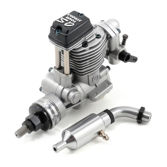
- Page 4 This manual handles the following two versions. BASIC ENGINE PARTS FS-30S, FS-40S Rocker Cover The FS Series engines are up-to-date overhead-valve four-stroke-cycle engines for Glow plug...
-
Page 5: Installation
3mm steel screw Steel washer Rigid hardwood for FS-30S (e.g. maple) 3.5mm steel screw At least 12mm At least 12mm (1/2") for FS-30S for FS-40S (1/2") for FS-30S At least Hardwood mounting beams 15mm(19/32") for FS-40S At least 15mm(19/32") for FS-40S... -
Page 6: Silencer
Battery leads Resistance coil (nichrome wire) 7 Fuel tank For installation in the model, a 150cc(5oz.) for FS-30S and FS-40S tank is suggested. These will allow 10 minute flight. Fuel bulb 8 Fuel bottle or pump Battery leads Fuel pumps For filling the fuel tank, a simple, polyethylene "squeeze"... -
Page 7: Fuel And Pressure Lines
9 Electric starter and starter battery Note: When cutting silicone tubing··· An electric starter is recommended Silicone tubing for starting. 10 Fuel can filter Install a filter in the outlet line of your refuelling container to prevent entry off oreign matter into Do not use wire cutters the fuel tank. -
Page 8: Starting The Engine
Do not run the engine too lean and do not leave the GLOWPLUG battery connected while adjusting the needle. The FS-30S and FS-40S are supplied with an O.S. Type F glowplug, specially designed for O.S. four- When to replace the glowplug stroke engines. - Page 9 Turn the needle-valve in the direction of arrow from the closed position. Turn the propeller 3 FS-30S (2 to 2-1/2 turns) to 4 turns counter- FS-40S (2-1/2 to 3 turns) clockwise smartly...
- Page 10 Check that the throttle is one-third open from the fully Needle-valve adjustment(1) closed position. Bring the starter into contact with the Slowly advance throttle to its spinner nut or spinner and depress the starter switch fully open position, then gradually close the needle- for one or two seconds.
-
Page 11: Running -In
Subsequent starting procedure On starting from cold, with the needle-valve Once the optimum needle-valve setting has been set at the rich starting position: established (see "Needle-valve adjustment- a good deal of white smoke is emitted. Summary") the procedure for starting is simplified as follows: As the needle-valve is closed and the r.p.m. -
Page 12: Carburetor
CARBURETOR These engines are equipped with a throttle type car- buretor which provides a wide range of engine speed control. With the throttle lever linked to a suitable servo in the model, movement of the throttle control on the transmitter will enable engine to be varied, proportionally, from idling speed to full power. -
Page 13: Carburetor Air-Bleed Adjustment
CARBURETOR AIR-BLEED ADJUSTMENT Start the engine. Pre-Flight Check Make sure that the throttle is fully open. Start engine and adjust needle- valve as previously described. ˚ 20-30 open from maximum Adjust the neede-valve. r.p.m. setting. Close the throttle gradually. Close the throttle gradually. Find the idling position. -
Page 14: Trouble Shooting When The Engine Fails To Start
TROUBLE SHOOTING WHEN THE ENGINE FAILS TO START Four key points For quick, reliable starting, the following four conditions are required. 1 Good compression. 2 Adequate "glow" at glowplug. 3 Correct mixture. 4 Sufficient electric starter rotating speed. If the engine fails to start, or does not keep running after being started, check symptoms against the following chart and take necessary corrective action. -
Page 15: Valve Adjusting
Note: VALVE ADJUSTING Valve clearances of all O.S. four-stroke-cycle ALL O.S. four-stroke engines have their valve(tappet) engines must be checked and reset ONLY WHEN clearances correctly set before they leave the factory. THE ENGINE IS COLD. However, if, after many hours of running time have Procedure is as follows: been logged, a loss of power is detected, or if the engine has to be disassembled or repaired as a result... -
Page 16: Care And Maintenance
Remove 0.04mm feeler, rotate prop through two Insert 0.04mm feeler gauge between valve stem and revolutions and recheck gap. rocker-arm and gently turn adjusting screw clockwise until it stops.(Fig.4.) If clearance is correct, loosen the locknut on the other rocker-arm and repeat steps 1 to 5 above. Turn with fingers until it stops. -
Page 17: O.s. Genuine Parts & Accessories
O.S. GENUINE PARTS & ACCESSORIES Valve Adjusting Propeller Locknut Set O.S.Glow Plug Radial Mount Set Tool Kit TYPE F For FS-30S (71908300) For FS-40S (45810100) For FS-40S (71906000) (72200060) (71615009) Flexible Exhaust Pipes Super Filter (L) NEEDLE VALVE EXTENSION 1010A (72108300) -
Page 18: Parts List
FS-30S ENGINE EXPLODED VIEW FS-30S PARTS LIST C.M2.6x12 Code No. Description 44113000 Screw Set 43004200 Rocker Cover C.M2.6x18 45761400 Rocker Support Assembly 45761410 Rocker Support ( C.M3x10 ) 45761600 Rocker Arm Retainer (2pcs.) 45761000 Rocker Arm Assembly (1pair) 45761100 Rocker Arm (1pc.) -
Page 19: Parts List
FS-40S ENGINE EXPLODED VIEW FS-40S PARTS LIST C.M2.6X12 Description Code No. 45213010 Screw Set 45204210 C.M3X18 Rocker Cover 45261400 Rocker Support Assembly 45261410 Rocker Support 45761600 Rocker Arm Retainer (2pcs.) 45261010 Rocker Arm Assembly (1pair) 45261110 Rocker Arm (1pc.) 45761200 Tappet Adjusting Screw 45260010 Valve Assembly (1pair) -
Page 20: Carburetor Exploded Views & Parts List
CARBURETOR EXPLODED VIEW & PARTS LIST TYPE 20N Description Code No. C.M2.6x7 22081408 Throttle Lever Assembly 22081313 Throttle Lever Retaining Screw N.+M3x6 Carburetor Rotor 45281200 43081100 Carburetor Body 45281700 Carburetor Retaining Screw(3pcs.) 22081811 Throttle Stop Screw 43081900 Needle-valve Assembly 45781970 Needle 43081960 Nozzle Assembly... -
Page 21: Three View Drawing
FS-30S THREE VIEW DRAWING Dimension(mm) Specification 4.89 cc ( 0.299 cu.in. ) Displacement 19.5mm ( 0.767 in. ) Bore 16.4mm ( 0.648 in. ) Stroke Practical R.P.M. 2,500-13,000 r.p.m. Power output 0.5ps / 10,000 r.p.m. 279g ( 9.56 oz. ) -
Page 22: Memo
MEMO 6-15 3-Chome Imagawa Higashisumiyoshi-ku Osaka 546-0003, Japan TEL. (06) 6702-0225 FAX. (06) 6704-2722 URL : http://www.os-engines.co.jp Copyright 2002 by O.S.Engines Mfg. Co., Ltd. All rights reserved. Printed in Japan. 080203...
Need help?
Do you have a question about the FS-30S and is the answer not in the manual?
Questions and answers