Makita BDF456 Technical Information
Hide thumbs
Also See for BDF456:
- User manual ,
- Instruction manual (49 pages) ,
- Instruction manual (53 pages)
Table of Contents
Advertisement
T
ECHNICAL INFORMATION
Model No.
Description
C
ONCEPT AND MAIN APPLICATIONS
Model BDF456 is the upgraded version of model BDF452, featuring:
More compact and lightweight design than BDF452
More comfortable operation will be provided by re-designed ergonomic grip
Compatible with the 18V Li-ion batteries equipped with the Battery protection circuit
designed to protect the battery from damages due to overdischarge, high temperature
or overload current
This product is available in the following variations.
Model No.
BDF456RHE
BDF456RHEW
BDF456RFE
BDF456RFEW
BDF456Z
BDF456ZW
BDF456SHE
BDF456SHEW
All models also include the accessories listed below in "Standard equipment".
S
pecification
Voltage: V
Capacity: Ah
Battery
Cell
Charging time (approx.):
Max output: W
No load speed:
min-
=rpm
1
Capacity of drill chuck: mm (")
Capacity: mm (")
Torque setting
Clutch torque setting: N.m (in.lbs)
Lock torque: N.m (in.lbs)
Max. fastening
torque: N.m (in.lbs)
Electric brake
Mechanical speed control
Variable speed control
Reversing switch
LED job light
Weight according to
EPTA-Procedure 01/2003*
*2 with Battery BL1815, *3 with Battery BL1830
*4 with the lightest battery available for the model
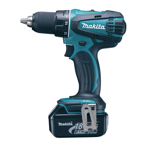
BDF456
Cordless Driver Drill
Battery
Battery
Type
Quantity
cover
BL1815
2
1
BL1830
2
1
No
No
No
BL1815
2
1
min.
High
Low
1.5 (1/16) - 13 (1/2)
Steel
Wood
16 stage + drill mode
1.0 - 5.0 (9 - 44)
Soft joint
Hard joint
1.5 (3.3)*
: kg (lbs)
4
Plastic
Charger
carrying case
DC18RA
Yes
DC18RA
Yes
No
No
DC18SD
Yes
18
1.3/ 3.0
Li-ion
15/ 22
with DC18RA
300
0 - 1,500
0 - 400
13 (1/2)
38 (1-1/2)
54 (480)
36 (320)
50 (440)
Yes
Yes (2 speed)
Yes
Yes
Yes
/ 1.7 (3.8)*
2
3
W
(with Battery BL1815)
Dimensions: mm (")
Housing
color
Length (L)
Makita blue
Width (W)
white
Height (H)
Makita blue
white
*2: with Battery BL1815
*3: with Battery BL1830
Makita blue
white
Makita blue
white
S
tandard equipment
+ - bit 2-45 ........ 1 pc
Belt clip ............ 1 pc
Note: The standard equipment for the tool
shown above may differ by country.
O
ptional accessories
Fast charger DC18RA
Charger DC18SD
Charger DC24SC
Automotive Charger DC18SE
Battery BL1815
Battery BL1830
Drill bits for wood
Drill bits for steel
Belt clip
Bit holder
OFFICIAL USE
for ASC & Sales Shop
PRODUCT
P 1/10
L
H
192 (7-9/16)
79 (3-1/8)
234 (9-1/4)*
2
251 (9-7/8)*
3
Advertisement
Table of Contents

Related Manuals for Makita BDF456


Summary of Contents for Makita BDF456
- Page 1 Description Cordless Driver Drill ONCEPT AND MAIN APPLICATIONS Model BDF456 is the upgraded version of model BDF452, featuring: More compact and lightweight design than BDF452 More comfortable operation will be provided by re-designed ergonomic grip Compatible with the 18V Li-ion batteries equipped with the Battery protection circuit...
- Page 2 P 2/10 epair CAUTION: Repair the machine in accordance with “Instruction manual” or “Safety instructions”. [1] NECESSARY REPAIRING TOOLS Code No. Description Use for Hex wrench 10 Removing / Assembling drill chuck Removing Drill chuck 1R359 Drill chuck removing tool (Use this tool if Drill chuck cannot be removed by the method described in “...
- Page 3 P 3/10 epair [3] DISASSEMBLY/ASSEMBLY [3]-1. Drill chuck (cont.) DISASSEMBLING (2) Remove Drill chuck. (Fig. 4) Fig. 4 *Note: The rotational direction is viewed from operator. 1. Grip Hex wrench 10 with Drill chuck and hold Machine. Important: Be sure to hold the grip of Machine tightly with sufficient counterclockwise* force against clockwise* recoil force of Machine.
- Page 4 P 4/10 epair [3] DISASSEMBLY/ASSEMBLY [3]-1. Drill chuck (cont.) ASSEMBLING (3) Tighten Drill chuck. (Fig. 7) Fig. 7 *Note: The rotational direction is viewed from operator 4. Open Keyless drill chuck fully, then drive M6x22 Flat head screw 1. Grip Hex wrench 10 with Drill chuck and hold Machine. by turning counterclockwise* Important: with Impact driver.
- Page 5 P 5/10 epair [3] DISASSEMBLY/ASSEMBLY [3]-2. Gear assembly and Motor section DISASSEMBLING (3) Disassemble Gear assembly and Motor section. (Fig. 9) Fig. 9 3. Unscrew nine 3x16 Tapping screws, 4. Remove the assembly of 5. Remove Speed change lever, then remove Housing (R). Motor section and Gear section.
- Page 6 P 6/10 epair [3] DISASSEMBLY/ASSEMBLY [3]-2. Gear assembly and Motor section (cont.) ASSEMBLING (3) Put Leaf spring in place on the inside of Housing (L). (Fig. 10) Fig. 10 Housing (L) Leaf spring Be sure to put Leaf spring in place as drawn on the right. (4) Insert Armature into Yoke unit carefully and connect Motor section to Gear assembly.
- Page 7 P 7/10 epair [3] DISASSEMBLY/ASSEMBLY [3]-2. Gear assembly and Motor section (cont.) ASSEMBLING (5) Engage the notch of Yoke unit with the projection inside of Housing (L) when mounting the assembly of Gear section and Motor section to Housing (L). (Fig. 12) Fig.
- Page 8 P 8/10 epair [3] DISASSEMBLY/ASSEMBLY [3]-3. Speed change lever ASSEMBLING Assemble Speed change lever to Gear assembly. (Fig. 14) Fig. 14 1. Be sure to put two 2. Mount Speed change lever to 3. Set Speed change lever to either Gear assembly.
- Page 9 P 9/10 ircuit diagram Fig. D-1 Color index of lead wires' sheath Black White Yellow Brush holder job light complete FET (Field effect transistor) Line filter Line filter is not used for some countries. Switch Connector Terminal...
- Page 10 P 10/10 iring diagram Fig. D-2 Lead wire wiring of Brush holder complete 2. Assemble Receptacles to 1. Pass Lead wires of Brush holder complete Lead wires. through Line filter if it is used. Line filter Line filter Line filter is not used Receptacle for some countries.
Need help?
Do you have a question about the BDF456 and is the answer not in the manual?
Questions and answers