Table of Contents
Advertisement
Quick Links
Advertisement
Table of Contents

Related Manuals for Akai ADV-55DR


Summary of Contents for Akai ADV-55DR
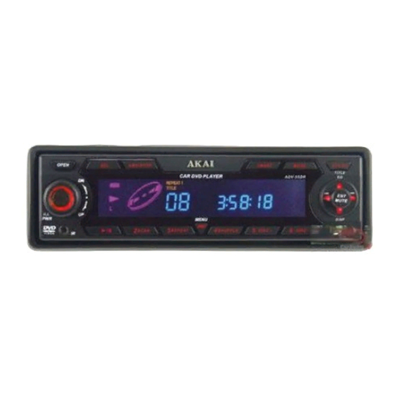
- Page 1 DVD/CD/MP3–RECIVER Model: ADV55DR SERVICE MANUAL www.akai.ru...
-
Page 2: Table Of Contents
CONTENTS Page Disassembly Instructions ............................3 Disassembly Diagram............................. 4 Operation Check..............................5 Block Diagram ................................ 6 Alignment Locations ............................... 7 Alignment Procedures ............................8 Printed Circuit Boards............................10 Exploded Views (Panel)............................18 Exploded View Parts Lists (Panel)........................19 Exploded Views (Cabinet) ............................ 20 Exploded View Parts Lists (Cabinet) ........................ -
Page 3: Disassembly Instructions
DISASSEMBLY INSTRUCTIONS 1. Using the unlock key that came with the unit or a similar tool, unlock the Mounting Box and remove toward the rear of the unit. 2. Remove two screws (A) located on the rear of the top cabinet then remove the Top Cabinet. 3. -
Page 4: Disassembly Diagram
DISASSEMBLY DIAGRAM... -
Page 5: Operation Check
OPERATION CHECK GENERAL SPECIFICATIONS OF SIGNAL Standard frequency 98.1 MHz (87.5, 108 MHz) 1000 kHz (522, 1620 kHz) 200 kHz (144, 288 kHz) Signal output 1 mV 5 mV 5 mV Modulation 400 Hz 30% MOD. FM Stereo 1 kHz 75 kHz DEV. -
Page 6: Block Diagram
BLOCK DIAGRAM (RADIO SECTION) - Page 7 BLOCK DIAGRAM (DVD SECTION)
-
Page 8: Alignment Locations
ALIGNMENT LOCATIONS MITSUMI TUNER... -
Page 9: Alignment Procedures
ALIGNMENT PROCEDURES FM ADJUSTMENT Equipment Required AM IF/RF signal generator Solid-state voltmeter (SSVM) Regulated DC power supply 2-CH voltmeter Distortion meter FM Alignment Using FM Signal Generator Note: Press the radio power switch to on the radio. Signal generator output must be kept as low as possible to avoid overload and clipping. -
Page 10: Printed Circuit Boards
PRINTED CIRCUIT BOARDS MAIN BOARD TOP VIEW... - Page 11 MAIN BOARD BOTTOM VIEW...
- Page 12 KEY BOARD TOP VIEW...
- Page 13 KEY BOARD BOTTOM VIEW...
- Page 14 CD SERVO BOARD TOP VIEW...
- Page 15 CD SERVO BOARD BOTTOM VIEW...
- Page 16 REMOTE BOARD TOP VIEW...
- Page 17 REMOTE BOARD BOTTOM VIEW...
-
Page 18: Exploded Views (Panel)
EXPLODED VIEW PANEL... -
Page 19: Exploded View Parts Lists (Panel)
EXPLODED VIEW PARTS LIST PANEL Ref. No. Description RS Part No. Mfr’s Part No. Lens: DVD-F1628X12.2.2.5/SW (SPY BLK/WHT) 53-G6230-37W T. Panel DVDF1628X12.2.2.5 (S. OP1202/B) W/O Brand 51-G6220-871 Bottom Cabinet 51-G6221-00 Open Knob For FD (S. OP1202/Black) 52-G6224-81B Open Knob Spring 36-00101-00 VOL Knob Cover (Electroplate-Silver) 52-G6223-90E... -
Page 20: Exploded Views (Cabinet)
EXPLODED VIEW CABINET... -
Page 21: Exploded View Parts Lists (Cabinet)
EXPLODED VIEW PARTS LIST CABINET Ref. No. Description RS Part No. Mfr’s Part No. Panel Ring (S. OP1202) 51-16228-80S Base N/Reset (DVD162) 51-H6230-00 Rear Bracket (Wire) (RDS) 61-D0406-00 DVD MECH. Slot Type (HPD-60) 94-02780-00 Heat Sink (CD100/104) Y/Wire 61-B0110-00 Top Cabinet 61-B0105-00 Bottom Cabinet (For Wire) 61-B0114-00... - Page 22 Ref. No. Description RS Part No. Mfr’s Part No. 12V DC FAN 30X30X7 49-03012-12 Hexagon Nut M2.0 35-40026-00 Wire Clip 1.0MM 39-B1415-00 Screw Ø5 X 18 HH 40-05018-04 Spring Washer M5 35-50001-00 Hexagon Nut M5 39-12620-00 Antenna Clip 1.0MM G.S.S. 39-A1526-00 Camera Screw M2X3 P/H (Black) 40-60203-20...
-
Page 23: Schematic Diagram
SCHEMATIC DIAGRAM (MAIN BOARD) - Page 24 SCHEMATIC DIAGRAM (MPEG)
- Page 25 SCHEMATIC DIAGRAM (KEY BOARD)
- Page 26 SCHEMATIC DIAGRAM (CD SERVO BOARD)
- Page 27 SCHEMATIC DIAGRAM (REMOTE BOARD) BATTERY 1.5Vx2...
-
Page 28: Electrical Parts List
ELECTRICAL PARTS LIST Ref. No. Part No. Description Q’ty PC BOARD ASSY, MAIN BOARD QC1,5,7,9,QP6,QM1 01-00106-00 KRA106S (SOT-23) QC4,6,8,QP2,3,5,QR1,13/4 01-00106-10 KRC106S (SOT-23) Q803~6,QA1,2 01-00231-00 KRC231S (SOT-23) 01-01132-00 TR. CHIP 2SB1132Q ROHM Q807/9,QC2,QR12 01-01298-00 KTA1298 (SOT-23) Q812 01-01385-00 KTA1385D (DPAK) Q801,QR11 01-03265-00 TR. - Page 29 ELECTRICAL PARTS LIST - CONTINUED Ref. No. Part No. Description Q’ty XC1,XR2 04-00072-00 CRYSTAL 7.2MHZ 04-00270-00S CRYSTAL 27MHZ (HC-49/US) ±5PPM 04-00433-04 CRYSTAL 4.332MHZ (HC-49/µS) CR17 05-16225-00 TAN CAP 2.2µF 16V C805~8,CA8,9,CC1,2,CR3,6 05-63102-00 CHIP 1000PF ±5% NPO 0603 SMT CR5,11,26,31 05-63103-01 CHIP 0.01µF ±10% X7R 0603 SMT C717,903/7,CR27,32,CV1,2,10/1/3,CC5,7, 05-63104-02...
- Page 30 ELECTRICAL PARTS LIST - CONTINUED Ref. No. Part No. Description Q’ty RR4,10,40/1,RM13 07-63100-00 CHIP RES 10Ω ±5% 0603 SMT RC14/5/7/8,26,44,RR7,9,42 07-63101-00 CHIP RES 100Ω ±5% 0603 SMT RN1,2 07-63101-04 CHIP CN34J RES 100Ω (0603X4 SMT) R703~10,801~4,852,913,RR1,2,8,14/5,36 07-63102-00 CHIP RES 1kΩ ±5% 0603 SMT ~9,43,RA10/1,RC16,RP2 R403/4,711,813,837/9,845/8,851/3,RR16, 07-63103-00...
- Page 31 ELECTRICAL PARTS LIST - CONTINUED Ref. No. Part No. Description Q’ty 09-70470-02 AX TYPE 4.7µH CHOKE COIL W/TC 11-10040-027 DVD1004 RDS MB D/S 182.4X151.3X1.2 15-05026-01 TRANS XDN-457A-T50-26B 16-00035-04 Ø3.5MM JACK (4PIN) W/SW 16-00035-10 Ø3.5MM JACK 4PIN BLACK 16-00035-20 Ø3.5MM JACK 4PIN YELLOW 20-10200-05 SINGLE RCA CABLE 200MM GREEN 20-20360-01...
- Page 32 ELECTRICAL PARTS LIST - CONTINUED Ref. No. Part No. Description Q’ty 07-63513-00 CHIP RES. 51kΩ ±5% 0603 SMT R12,26 07-63681-00 CHIP RES. 680Ω ±5% 0603 SMT 07-63751-00 CHIP RES. 750Ω ±5% 0603 SMT 07-63752-00 CHIP RES. 7.5kΩ ±5% 0603 SMT 07-63822-00 CHIP RES.
- Page 33 ELECTRICAL PARTS LIST - CONTINUED Ref. No. Part No. Description Q’ty C105 05-63470-00 CHIP CAP 47PF ±5% NPO 0603 SMT C113/4 05-63471-00 CHIP CAP 470PF ±5% NPO 0603 SMT C222,401 05-63472-01 CHIP 4700PF ±10% X7R 0603 SMT C102,112,214 05-63473-01 CHIP 0.047µF ±10% X7R 0603 SMT C111,231,309 05-63474-00 CHIP CAP 0.47µF Y5V +80%...
- Page 34 ELECTRICAL PARTS LIST - CONTINUED Ref. No. Part No. Description Q’ty R105,117,202 07-63512-00 CHIP RES 5.1kΩ ±5% 0603 SMT R108 07-63513-00 CHIP RES. 51kΩ ±5% 0603 SMT R103 07-63563-00 CHIP RES. 56kΩ ±5% 0603 SMT R203,220 07-63822-01 CHIP RES 8.2kΩ ±5% 0603 SMT L21/2 09-00100-54 INDUCTOR 10µH SMD 0805...
- Page 35 ELECTRICAL PARTS LIST - CONTINUED Ref. No. Part No. Description Q’ty PC BOARD ASSY, JB. EL DRIVER SECTION 01-00435-00S TR BD435S NPN TO-126 FAIRCHLD 01-03875-07 TRANSISTOR 2SC3875G DD1~3,QC21 02-04148-02 DIO CHIP RLS4148 1206 ROHM ZD1,2 02-50068-54 CHIP ZENER DIODE 6.8V (LL-34) 02-50100-02 CHIP ZENER DIODE 10V ±5% (LL-34) 05-05474-00F...
-
Page 36: Specifications
SPECIFICATIONS T. H. D............................Less than 0.35% Signal to Noise Radio ........................More than 60 dB Channel Separation ........................More than 60 dB Frequency Response ........................20Hz - 20kHz Stereo Separating (FM) ........................30 dB (at 1kHz) Signal to Noise Ratio (FM) ......................Better than 50 dB Output Power.............................
Need help?
Do you have a question about the ADV-55DR and is the answer not in the manual?
Questions and answers