Table of Contents
Advertisement
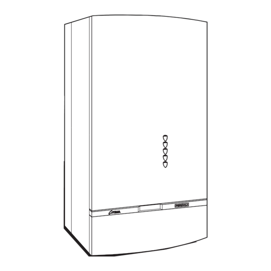
FAN ASSISTED, GAS COMBINATION BOILER
Phone numbers:
Installer
Service Engineer
Serial No.
Stockton Close, Minworth Industrial Park, Minworth, Sutton Coldfield, West Midlands B76 18DH
WALL MOUNTED, ROOM SEALED,
ALL SPECIFICATIONS SUBJECT TO CHANGE
Sales: 0121/3523500 - Fax 0121/3523510
601
INSTALLATION
INSTRUCTIONS
FERROLI HELPLINE
FOR SERVICE INFORMATION OR
HELP TELEPHONE: 0121 3523500
ALWAYS QUOTE YOUR SERIAL NUMBER
FOR IMMEDIATE ASSISTANCE
05/97
Advertisement
Table of Contents

Related Manuals for Ferroli optima 601


Summary of Contents for Ferroli optima 601
- Page 1 05/97 WALL MOUNTED, ROOM SEALED, FAN ASSISTED, GAS COMBINATION BOILER INSTALLATION INSTRUCTIONS FERROLI HELPLINE Phone numbers: FOR SERVICE INFORMATION OR HELP TELEPHONE: 0121 3523500 Installer ALWAYS QUOTE YOUR SERIAL NUMBER FOR IMMEDIATE ASSISTANCE Service Engineer Serial No. ALL SPECIFICATIONS SUBJECT TO CHANGE...
-
Page 2: Table Of Contents
page INDEX General Description Preparing the Flue Assembly Related Documents Connecting the Boiler Technical Data Fitting the Flue Assembly Appliance Dimensions Electrical Installation Boiler Flow Diagram Commissioning & Testing Key of boiler flow diagram Filling the Central Heating System Installation Details Filling the Domestic Hot Water System Location of Boiler Electricity Supply... -
Page 3: General Description
General Description The Ferroli 601 is a wall mounted, room sealed, fan assisted, combination boiler for Central Heating (C.H.) and domestic Hot Water (D.H.W.). The boiler is of light weight construction and the heat exchanger provides Central Heating and Domestic Hot Water from an integrally designed unit. -
Page 4: Technical Data
Technical Data Nominal Heat Input D.H.W. & C.H. (gross) 28.6 kW 28.0 kW Minimum Heat Input D.H.W. & C.H. (gross) 12.8 kW 12.5 kW Nominal Heat Input D.H.W. & C.H. (net) 25.8 kW 25.8 kW Minimum Heat Input D.H.W. & C.H. (net) 11.5 kW 11.5 kW Nominal Heat Output D.H.W. -
Page 5: Appliance Dimensions
Appliance Dimensions FRONT VIEW LEFT SIDE VIEW REAR VIEW 97.5 77.5 1. Electricity cable entry Fig. 1 2. Gas supply 8 - TOP VIEW 3. Domestic Hot Water outlet 4. Domestic Cold Water inlet 5. Central Heating Pressure relief valve 6. -
Page 6: Boiler Flow Diagram
Boiler Flow Diagram Fig. 2... - Page 7 nal) 1. Fixing point 42. D.H.W. temperature sensor 5. Room sealed compartment 43. Air pressure switch 6. Control panel 44. Combination gas valve 7. Gas inlet 45. Knob gas valve 8. Domestic hot water outlet 46. Operator gas valve 9. Cold water inlet 47.
-
Page 8: Installation Details
Installation Details Gas Safety (Installation & Use) Regulations: 1994 In the interest of safety, it is the law that all gas appliances are installed by a competent person in accordance with the above Regulations, Building Regulations/Building Standards Scotland, Codes of Practice, current I.E.E. -
Page 9: Minimum Clearance
Terminal Position Minimum Clearance mm NOTES * Access to the front of the boiler must be available for maintenance (min. 600 mm). -
Page 10: Flue System
Flue system The boiler allows the flue outlet to be taken from the rear of the boiler or from either side. A standard flue length of 0.75 metres is provided. Alternative lengths of two or three metres can be supplied (equivalent to wall thicknesses of up to 565, 1815 and 2815 mm for rear flues and deduct 91 mm plus distance from side wall for side outlet flues). - Page 11 Cold water Additional expansion vessel C.H. (if required) Filling point C.H. Bypass Fig. 6 NOTE: A bypass must be fitted as far as possible from the boiler if thermostatic radiator valves are fitted throughout. 1. Filling point C.H. 2. Temporary connection Fig.
- Page 12 Built-in Central Heating Water Circulating Pump The pump head available for circulating the water is given in fig. 8. N.B. - The pump is factory set at position 3. The pump is a Grundfos type 25-50 UPS series. Grunfos Pump performance graph Note - Minimum flow through boiler heat exchanger at any time should not fall below 6 litres per minute.
- Page 13 Installation Note - To mount the boiler on the wall, a two person lift will be needed. UNPACKING The appliance is delivered in 2 cartons. The large carton contains the boiler, and the Installation/Servicing and Users Instructions. The second carton contains the mounting jig assembly, complete with isolating valves, the assembly fixing screws and wall plugs (x4), the boiler mounting nuts and washers (x2), drilling template, flue assembly and flue bend.
-
Page 14: Gas Supply
Flush out the water system. Note - The maximum inlet cold water pressure must not exceed 10 bar (145 P.S.I.) and a water governor or a pressure reducing valve will be required if the pressure is in excess of 5 bar (72 P.S.I.). Ensure all pipework is adequately supported. - Page 15 PREPARING THE FLUE ASSEMBLY Rear Flue Outlet (fig. 12) Important - The aluminium flue pipe must protrude into the outside grill by 60 mm, never cut it to the same length as the plastic air pipe (aluminium flue pipe = plastic air inlet pipe + 70 mm !). Aluminium flue pipe length = Plastic air inlet pipe length plus 70 mm longer.
- Page 16 Place the boiler on its back. Remove the boiler base plate, four screws (fig. 16). Remove the plugs fitted to the boiler water connections. Remove the bag of sealing washers from the boiler pipework. Remove the front panel by gripping on both sides, sliding up and pulling away from the main boiler.
- Page 17 Fixing points Fig. 15 Lift here Fixing screws Fig. 16 Fig. 17...
- Page 18 FITTING THE FLUE ASSEMBLY With Sufficient Clearance To Insert Assembly From Inside 6.1.1 Insert the flue assembly into the wall. 6.1.2 Insert the flue bend in the top plate of the boiler 6.1.3 Secure the flue bend. 6.1.4 Fully insert the flue assembly into the boiler flue bend. Insert the self tapping screw supplied. Fully tighten. 6.1.5 Check the terminal relationship with the wall as shown in fig.
- Page 19 COMMISSIONING AND TESTING Filling the Central Heating System Burner pressure Automatic air vent Vent cap test point Heat exchanger vent Pump D.H.W. expansion pressure gauge vessel (optional) Low water pressure switch C.H. pressure relief valve Gas inlet pressure test point D.H.W.
- Page 20 Pilot viewing opening C.H. pressure gauge C.H. boiler thermostat Gas valve control knob fig. 21 8.5 To Light the Boiler (fig. 21) a. Open controls panel door. b. Switch on electricity supply. c. Adjust room thermostat and all external controls to «ON». Check operation of pump. d.
- Page 21 Burner Pressure C.H. and D.H.W. To Range Rate the Boiler C.H. (not required on standard installations). The boiler can be range rated for an output from 9.7 kW up to 23.3 kW. When the boiler is supplied it is factory set at the maximum output 23,3 kW. Procedure a.
- Page 22 Honeywell VR 4600 N 4002 valve with V7335A4014 Modureg Gas pressure Adjustment With the burner lit: Connect suitable pressure gauge to burner test point "B", and then: Disconnect air pressure compensation tube "H"; Disconnect the wires from coil "C" of the Modureg; Remove protective cover "D";...
- Page 23 2.7 mbar +/- 0.5 mbar. If the burner pressure is not as stated check the inlet working pressure (fig. 22) which should be minimum 20 mbar. If that is correct, consult Ferroli. No attempt should be made to alter D.H.W. burner pressure.
-
Page 24: Spare Parts List
Spare Parts List Item No.G.C. Part No.Makers Part NoNo. OffDESCRIPTION 386816 800130 C.H. safety valve 372310 803860 Complete fan 372176 815850 Main injector (Natural Gas) 815870 Main injector (L.P.G.) 390210 801170 Thermocouple 386575 801090 Spark electrode 386586 800270 Pilot 386814 800600 Central heating pump 386818... -
Page 25: Domestic Hot Water Performance
Domestic Hot Water Performance Fig. 1 - D.H.W. Pressure Drop VS. flow A = Standard with cold water Flow Restricter B = Cold Water Flow Restricter Removed Fig. 2 - D.H.W. temperature VS. flow A = Cold Water 15°C Fig. 1 B = Cold Water 5°C Fig. - Page 26 24 V 230V ~ 50 Hz. NOTE: THE TRANSFORMER ON THE P.C.B. HAS A BUILT-IN OVERHEAT PROTECTION. IF THIS IS OPEN, ALL LED'S WILL BE OFF BUT THE C.H. PUMP (32) WILL RUN SWITCH OFF THE BOILER FOR AT LEAST 20 MINUTES 230V CONNECTOR X7 1-2 = 230 V...
- Page 27 General Notes - For use on the fitted with VMF7 Printed Circuit Board *The pilot light can only be ignited after the Fan (16) has run for at least 20 seconds on full speed. *The central heating pump (32) will run to disperse heat if the temperature at the heat exchanger limit thermostat (50) is too high *The frost thermostat (51) will switch on the boiler for central heating if the temperature is too low.
- Page 28 Special Installation Possibilities: Two-pipe air intake/flue outlet Special Air Intake/Flue Outlet The standard Flue/air intake hood on top of the boiler can be replaced by a special two pipe flue adapter. Ø80 Ø80 = Special two pipe flue adapter 823071 = remove air intake cover Ø...
- Page 32 Phone numbers: Installer Service Engineer BECAUSE OF OUR CONSTANT ENDEAVOUR FOR IMPROVEMENT DETAILS MAY VARY SLIGHTLY FROM THOSE QUOTED IN THESE INSTRUCTIONS. ALL SPECIFICATIONS SUBJECT TO CHANGE Stockton Close, Minworth Industrial Park, Minworth, Sutton Coldfield, West Midlands B76 8DH Sales: 0121/3523500 - Fax 0121/3523510...
Need help?
Do you have a question about the optima 601 and is the answer not in the manual?
Questions and answers