Table of Contents
Advertisement
Quick Links
Professional Shop Manual
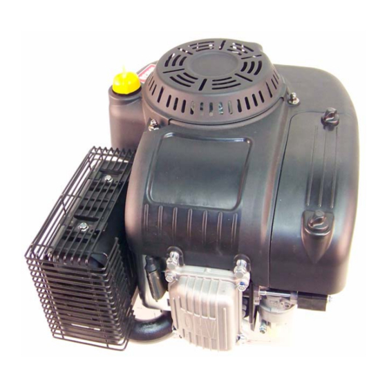
P90 Series Vertical Shaft Engines
NOTE: These materials are for use by trained technicians who are experienced in the service and repair of outdoor power
equipment of the kind described in this publication, and are not intended for use by untrained or inexperienced individuals.
These materials are intended to provide supplemental information to assist the trained technician. Untrained or inexperi-
enced individuals should seek the assistance of an experienced and trained professional. Read, understand, and follow all
instructions and use common sense when working on power equipment. This includes the contents of the product's Oper-
ators Manual, supplied with the equipment. No liability can be accepted for any inaccuracies or omission in this publication,
although care has been taken to make it as complete and accurate as possible at the time of publication. However, due to
the variety of outdoor power equipment and continuing product changes that occur over time, updates will be made to these
instructions from time to time. Therefore, it may be necessary to obtain the latest materials before servicing or repairing a
product. The company reserves the right to make changes at any time to this publication without prior notice and without
incurring an obligation to make such changes to previously published versions. Instructions, photographs and illustrations
used in this publication are for reference use only and may not depict actual model and component parts.
© Copyright 2011 MTD Products Inc. All Rights Reserved
Advertisement
Table of Contents
Troubleshooting

Related Manuals for MTD P90 series


Summary of Contents for MTD P90 series
- Page 1 Instructions, photographs and illustrations used in this publication are for reference use only and may not depict actual model and component parts. © Copyright 2011 MTD Products Inc. All Rights Reserved...
-
Page 3: Table Of Contents
Table of Contents Chapter 1: Introduction Professional Service Manual Intent ........1 Safety . - Page 4 Chapter 4: The Fuel System and Governor Inspecting the fuel ..........33 Test fuel for alcohol .
- Page 5 Chapter 8: Exhaust Spark arrestor (if equipped) ........79 Muffler removal/replacement .
-
Page 7: Chapter 1: Introduction
• Common sense in operation and safety is assumed. • In no event shall MTD be liable for poor text interpretation or poor execution of the procedures described in the text. • If the person using this manual is uncomfortable with any procedures they encounter, they should seek the help of a qualified technician or MTD Technical Support. - Page 8 P90 Series Vertical Shaft Engines • Be prepared in case of emergency: ! CAUTION ! CAUTION Keep a fire extinguisher nearby Keep a first aid kit nearby Keep emergency contact numbers handy • Replace any missing or damaged safety labels on shop equipment.
-
Page 9: Fasteners
Introduction Fasteners • Most of the fasteners used on the MTD engine are metric. Some are fractional inches. For this reason, wrench sizes are frequently identified in the text, and measurements are given in U.S. and metric scales. • If a fastener has a locking feature that has worn, replace the fastener or apply a small amount of releas- able thread locking compound such as Loctite®... - Page 10 P90 Series Vertical Shaft Engines MTD Vertical Engine Model Designators 1 P 6 1 M U A • Starter/Alternator 1=Recoil start Major Revision • 2=Electric start (12V) • 3=E. start/alt. 18W Change • 4=E. start/alt. 3A/5A • 5= AutoChoke/ Recoil Compliance •...
-
Page 11: Model And Serial Number
Introduction Model and serial number The model and serial number can be found on a white sticker with a bar code. The sticker is located between the dipstick and the muffler. See Figure 1.1. Model /serial number Oil screen Muffler Dipstick Figure 1.1 NOTE: The serial number will always start with the model number. -
Page 12: Spark Plugs
Cleaning the spark plug: NOTE: MTD does not recommend cleaning spark plugs. Use of a wire brush may leave metal deposits on the insulator that causes the spark plug to short out and fail to spark. Use of abrasive blast for cleaning may cause damage to ceramic insulator or leave blast media in the recesses of the spark plug. -
Page 13: Air Filter
The main function of the air filter is to trap air borne particles before they enter the engine. Dirt ingestion can cause serious internal engine damage. Air filters used on the MTD engine are designed to prevent particles larger than 3-5 micron from passing through into the engine. -
Page 14: Oil Type And Capacity
P90 Series Vertical Shaft Engines Oil type and capacity The recommended oil for MTD engines is an SAE 10W-30 oil with an SM API rating or better. The oil capacity for all of the P90 series engines is 57 fl.oz (1.7 liters). -
Page 15: Changing The Oil
Introduction Changing the oil The oil change interval is every 100 hrs. NOTE: The first oil change should be preformed at 8 hours. NOTE: The oil filter should be replaced when the oil is changed. To change the oil: Remove the cap from the oil drain. See Figure 1.5. Remove the dipstick. -
Page 16: Oil Filter
P90 Series Vertical Shaft Engines Oil filter To replace the oil filter: Drain the oil by following the steps described in the previous section of this chapter. Clean the area around the oil filter Remove the oil filter by turning it counter-clockwise, as seen from the left side of the engine. -
Page 17: Fuel System
Carefully slide the fuel lines off of the filter. If there are pieces of rubber on the barbs of the fuel filter, replace the affected fuel line. IMPORTANT: The P90 series engines uses low permeation fuel line to meet EPA guidelines. When replacing the fuel lines, they must be replaced with the same type of low permeation fuel line. -
Page 18: Valve Lash
P90 Series Vertical Shaft Engines Valve lash Valve lash is the clearance between the top of the valve stem and the rocker arm. The valve lash should be checked after the first 25 hours of use and every 100 hours after that. Valve lash can be checked and adjusted using the following steps:. - Page 19 Introduction .005” feeler gauge Check valve lash between each valve stem and rocker arm using a feeler gauge. Intake valve lash (top valve) should be 0.004” - 0.006” (0.10 - 0.15mm). See Figure 1.12. Figure 1.12 Exhaust valve lash (bottom valve) should be 0.006” - 0.008”...
-
Page 20: Exhaust System
P90 Series Vertical Shaft Engines Exhaust system The exhaust system is a frequently overlooked component of an engine. It is important to make sure the muffler is in good condition and free of blockage. NOTE: A blocked muffler will result in poor performance. If a muffler is completely blocked, the engine may not start. -
Page 21: Chapter 2: Basic Troubleshooting
Also check attachments for damage and make sure they are firmly mounted. Steps to troubleshooting NOTE: The steps and the order of the steps that follow are a suggested approach to troubleshooting the MTD engine. The technician does not necessarily have to follow them as described in this chapter. - Page 22 P90 Series Vertical Shaft Engines IV. Unusual exhaust tone There are tools that the technician can use in order to define the problem, such as: Interview the customer. 1a. Get a good description of their complaint. 1b. If it is an intermittent problem, verify what conditions aggravate the problem as best as possible.
-
Page 23: Identify Factors That Could Cause The Problem
ASIC ROUBLESHOOTING Identify factors that could cause the problem This is the second step in the troubleshooting process. Crankshaft will not turn. A. Starter not working. This can be an electrical failure or a mechanical failure. The likely suspects are: A dead battery. - Page 24 P90 Series Vertical Shaft Engines Run the engine with a spark tester in-line between the spark plug wire and the spark plug or use an oscilloscope and see if the spark goes away at the same time the engine dies.
- Page 25 ASIC ROUBLESHOOTING V. Makes unusual smoke when running a. Black smoke, usually heavy, usually indicates a rich air fuel mixture • Not enough air: air flow blockage or a partially closed choke. • Too much fuel: carburetor float or float valve stuck or metering / emulsion issues with the car- buretor.
- Page 26 P90 Series Vertical Shaft Engines chirping noise. • Confirm with a compression test and leak-down test. e. Unusual exhaust tone Splashy or blatty • Splashy idle usually indicates a slight rich condition. • May indicate an exhaust blockage, usually slightly muffled.
-
Page 27: Repairing The Problem
ASIC ROUBLESHOOTING Repairing the problem The third step in the troubleshooting process is to repair the problem. This step consists of: A. Form a diagnosis by using all of the information gathered from the troubleshooting that was performed. B. Physically perform the repair. The fourth, and hopefully final, step in the troubleshooting process is the follow through. -
Page 28: Prime Test
P90 Series Vertical Shaft Engines Prime test To perform a prime test: Prime the engine through the carburetor throat using a squirt bottle, filled with clean fresh gasoline. Make sure the throttle is in the run position. Attempt to start the engine. - Page 29 ASIC ROUBLESHOOTING Compare the results to the following chart. Leak-down Testing Results Symptom Possible cause Air escaping from Worn cylinder or piston rings. the breather Possible blown head gasket Air escaping from Leaking exhaust valve the exhaust Air escaping from Leaking intake valve the carburetor Gauge reading...
-
Page 30: Compression Test
P90 Series Vertical Shaft Engines Compression test To perform a compression test: NOTE: Compression should be in the range of 55 - 80 PSI (3.8 - 5.5 Bar). • Disconnect the high-tension lead from the spark plug and ground it well away from the spark plug hole. -
Page 31: Pcv Testing
The cause of this oil burning can be mistaken for a worn-out engine, if proper diagnosis (compression, leak- down, and case pressure) is not performed. Experimentation by MTD’s Training and Education Department has revealed the following characteristics of MTD engines: •... - Page 32 P90 Series Vertical Shaft Engines...
-
Page 33: Chapter 3: Air Intake System
A combination of the two are used on the MTD engine. See Figure 3.1. • Air filters used on the MTD engine are designed to prevent particles larger than 3-5 micron from pass- ing through into the engine. - Page 34 P90 Series Vertical Shaft Engines Lift the air filter cover off the engine. Remove the air filter assembly. Air filter Figure 3.3 Install the air filter by following the previous steps in reverse order. NOTE: The air filter housing is part of the blower cover.
-
Page 35: Blower/Air Filter Housing
NTAKE YSTEM Blower/air filter housing On the P90 series of engine, the air filter housing is part of the blower housing. To remove/replace the blower/air filter housing: Remove the air filter following the steps described in the previous section of this chapter. -
Page 36: Carburetor And Insulator
Disconnect the fuel line from the carburetor. NOTE: MTD uses low permeation fuel lines to meet EPA guidelines. Low permeation fuel lines are made with a soft membrane that lines the inside of the line. Any tear in this membrane will allow the fuel to get in between the membrane and the hose, choking off the fuel flow. - Page 37 NTAKE YSTEM Double nut the carburetor studs and remove them. See Figure 3.10. NOTE: The insulator block and gaskets may fall out when the studs are removed. NOTE: The most likely reason to remove the insulator block and its gaskets is to cure a lean running con- dition.
- Page 38 P90 Series Vertical Shaft Engines Install the carburetor by following the previous steps in reverse order. Gasket Gasket NOTE: Use new gaskets between the cylinder Gasket head, the insulator, the carburetor and the intake manifold. NOTE: Tighten the carburetor nuts to a torque of 62 Studs - 80 in lbs (7 - 9 Nm).
-
Page 39: Chapter 4: The Fuel System And Governor
YSTEM AND OVERNOR CHAPTER 4: THE FUEL SYSTEM AND GOVERNOR The function of the fuel system is to store fuel, mix the fuel with air in the correct ratio and deliver it to the intake port. The fuel system consists of the following components: •... -
Page 40: Test Fuel For Alcohol
This results in less power for the engine. A 10% ethanol (E10) mix is acceptable for MTD engines. Anything higher than that will result in performance issues. -
Page 41: Choke/Throttle Cable Adjustment
YSTEM AND OVERNOR Choke/throttle cable adjustment The choke/throttle cable will need to be adjusted any time the cable or the control panel is replaced. NOTE: The procedures to remove/replace the choke/throt- Choke lever tle cable can be found in the service manual for the piece of equipment that the engine is mounted to. -
Page 42: Carburetors
P90 Series Vertical Shaft Engines Carburetors If diagnosis indicates a fuel problem, inspect the carburetor. This is important even if problems are identified elsewhere in the fuel system. IMPORTANT: The fuel must be tested for alcohol content before diagnosing anything else on the engine. -
Page 43: Disassembly And Rebuilding The Carburetor
YSTEM AND OVERNOR Disassembly and rebuilding the carburetor Remove the carburetor by following the procedures described in Chapter 3: Air Intake System. NOTE: An insulator separates the carburetor from the cylinder head. • A bowl vent port is in a recessed passage on the end of the carburetor that faces the insulator. •... - Page 44 P90 Series Vertical Shaft Engines NOTE: Because the float valve is crucial to the func- Float tioning of the carburetor and the viton tip of the valve is subject to wear, technicians should replace the valve and spring any time the carburetor is disassembled for cleaning.
- Page 45 YSTEM AND OVERNOR Throttle stop screw The throttle stop screw has a large pliable lip around the head of the screw. That lip secures a metering Welch plug plug for the pilot and transition ports. Remove the screw to reach the plug. See Figure 4.11. Shot plug in feed bore Fuel feed leg...
- Page 46 P90 Series Vertical Shaft Engines Transition ports Pilot port NOTE: The pilot screw regulates how much of this pre-mixed fuel/air emulsion is allowed to Pilot screw enter the throat of the carburetor, to atomize (before head down-stream of the throttle plate. On current...
-
Page 47: Engine Speed Adjustment
YSTEM AND OVERNOR Engine speed adjustment To adjust the engine speed: Start the engine and let it reach operating tempera- ture. Move the throttle control lever to the full throttle posi- tion. Measure the engine’s speed using a tachometer. Bend the tab, that the governor spring is attached to, as needed to adjust the engine speed to 3,300 RPM + 100. -
Page 48: Afterfire Solenoid
P90 Series Vertical Shaft Engines Afterfire solenoid When an engine is turned off, the engine does not “instantly” stop spinning. As the engine slows down, it is still drawing fuel out of the carburetor. This raw fuel passes through the engine because the ignition system is grounded to prevent the spark plug from firing. - Page 49 YSTEM AND OVERNOR Old style NOTE: Early production engines have a simple bullet con- nector between the stator and the afterfire solenoid (power lead). Current production engines have locking bullet connectors. The two connectors are not interchangeable. All new stators and afterfire solenoids sold as service parts will have the new connectors.
-
Page 50: Testing The Afterfire Solenoid
P90 Series Vertical Shaft Engines Testing the afterfire solenoid An afterfire solenoid that is not working properly can prevent the engine from starting. The solenoid itself rarely fails, usually there is some type of fault in the wiring to the solenoid to prevent it from energizing. - Page 51 YSTEM AND OVERNOR With the ignition key in the “on” position, test for volt- Afterfire solenoid lead from main harness age at the power lead connection. See Figure 4.21. • If battery voltage is present, bench test the sole- noid. •...
-
Page 52: Governor
P90 Series Vertical Shaft Engines Governor The engine speed is controlled by a balance between the force applied by a spring (pulling the throttle open) and a flyweight mechanism within the engine apply- ing force to the governor arm (pushing the throttle closed). - Page 53 YSTEM AND OVERNOR Put an alignment mark on the governor arm and shaft. See Figure 4.26. Loosen the nut and T-bolt that secures the governor arm to the shaft. 10. Carefully spread open the seam on the arm. 11. Carefully slide the Governor arm off of the governor shaft.
-
Page 54: Governor Shaft
P90 Series Vertical Shaft Engines Governor shaft To remove or replace the governor shaft: Remove the engine from the equipment that it pow- ers. Remove the governor arm by following the proce- dures described in the governor arm section of this chapter. -
Page 55: Chapter 5: Lubrication
CHAPTER 5: LUBRICATION Oil type and quantity The recommended oil for MTD engines is an SAE 10W-30 oil with an SM API rating or better. The oil capacity for all of the P90 series engines is 57 fl.oz (1.7 liters). -
Page 56: Oil Dipstick
P90 Series Vertical Shaft Engines Oil dipstick To check the oil: Fully seat the dip stick Twist and remove the dipstick from the engine. before reading it Clean the oil off of the tip of the dipstick. Re-insert the dipstick and turn it until it is fully seated to get the oil level reading. -
Page 57: Lubrication System
Lubrication Lubrication system The 4P90 engine uses a combination pressurized and splash lubrication system. There is an oil pump in the Balance shaft sump that is driven by the balance shaft. The oil is drawn into the pump through a pre-screen. The pump pushes the oil through a relief valve then into the oil filter. - Page 58 P90 Series Vertical Shaft Engines Check the oil level. NOTE: Top off the oil as needed with an SAE 10W- 30 oil with an SM API rating or better Start the engine. Let the engine run until the oil reaches operating tempurature 176°...
-
Page 59: Positive Crankcase Ventilation Valve
Lubrication Positive crankcase ventilation valve The PCV valve is located under the flywheel and allows the crankcase pressure to escape. The function and test procedures for the PCV is covered in Chapter 2: Basic Troubleshooting. To service the PCV: Remove the flywheel by following the steps described PCV cover in the Chapter 7: Ignition System. - Page 60 P90 Series Vertical Shaft Engines Inspect the oil drain-back port. Make sure it will allow oil to drain back into the engine. Oil drain port See Figure 5.10. Reassemble the PCV valve. Tighten the cover bolts to a torque of 53 - 71 in lbs (6 - 8Nm).
-
Page 61: Chapter 6: Starter And Charging Systems
Starter and Charging System CHAPTER 6: STARTER AND CHARGING SYSTEMS Starter removal To remove/replace the starter assembly: Starter screws Disconnect the negative battery cable. Disconnect the starter cable using a 10 mm wrench. Remove the two screws that secure the starter to the engine using a 12 mm wrench. -
Page 62: Bench Testing The Electric Starter
P90 Series Vertical Shaft Engines Bench testing the electric starter IMPORTANT: Always bench test an electric starter before condemning it. To bench test an electric starter: Remove the starter by following the procedures described in the previous section of this chapter. -
Page 63: Rebuilding The Starter
Starter and Charging System Rebuilding the starter The starter motor used on the 4P90 engine is a perma- nent magnet dc motor with a radial commutator, similar to what is found in a repulser start motor. A radial commuta- tor means that the commutator plates are perpendicular to Springs the axis of the rotor. - Page 64 P90 Series Vertical Shaft Engines Slide the stator housing off of the starter. Pull the rotor out of the stator housing. NOTE: The rotor will be held to the stator by strong Rotor magnets. Inspect the rotor for signs of wear or damage.
- Page 65 Starter and Charging System 12. Remove the nut and washers from the cable stud using a 10 mm wrench. See Figure 6.10. Washers 13. Remove the cable stud and the positive brushes. 14. Remove the insulator seal. Seal Figure 6.10 15.Remove the bearing: 5/16”...
- Page 66 P90 Series Vertical Shaft Engines Remove the screw, indicated by the arrow in Figure 6.13., from the topside of the starter gear housing using a #2 phillips screwdriver. Figure 6.13 Separate the starter gear housing. See Figure 6.14. Remove the pinion gear.
- Page 67 Starter and Charging System Screw extractor 22. Remove the bushing from the clutch/pinion cover. See Figure 6.16. NOTE: A blind hole bearing puller with a 11mm arbor or an screw extractor can be used. Figure 6.16 23. Drive the rotor upper bearing out of the clutch/pinion cover using a flat tipped punch.
- Page 68 P90 Series Vertical Shaft Engines To re-assembly a starter motor: Press the bushing into starter gear housing until there is 0.055” (1.4 mm) sticking out. See Figure 6.18. 0.055” Figure 6.18 Press the rotor’s upper bearing into the clutch/pinion Bearing cover until it is flush with the cover.
- Page 69 Starter and Charging System Clutch/pinion gear assembly Insert the clutch/pinion gear assembly into the starter gear housing. See Figure 6.21. Figure 6.21 Install the pinion gear. See Figure 6.22. Pinion gear clutch/pinion cover Figure 6.22 Mount the clutch/pinion cover to the starter gear housing.
- Page 70 P90 Series Vertical Shaft Engines Clean the carbon from the commutator. NOTE: A pencil eraser is very effective in cleaning commutators. See Figure 6.24. Figure 6.24 Rotor assembly Insert the splined end of the rotor into the starter gear housing. See Figure 6.25.
- Page 71 Starter and Charging System 11. Press a new bushing into the end cap until it is flush with the casting. See Figure 6.27. Bushing is flush with casting Figure 6.27 positive brushes/cable stud assembly 12. Insert the seal into the end cap from the inside. 13.
- Page 72 P90 Series Vertical Shaft Engines NOTE: A special tool will be needed to compress the brushes for assembly of the motor. See Figure 6.30. To make the tool: 1 5/8” A. Cut a piece of sheet metal approximately 0.040” thick (19 or 20 gauge).
- Page 73 Starter and Charging System 22. Set the starter motor onto the end cap while keeping the brushes compressed into the brush holder. See Figure 6.33. 23. Carefully slide the brush holding tool out of the starter. 24. Rotate the end cap to line up the alignment marks with the stator housing.
-
Page 74: Charging System
P90 Series Vertical Shaft Engines Charging system The charging system used on MTD engines consists of a dual output alternator and a rectifier/regulator. The charging system has a 5 amp AC output and a 3.75 amp DC output. The alternator consists of two parts;... -
Page 75: Charging System Testing
Starter and Charging System Charging system testing To test the charging system: Locate the connection between the engine harness Engine harness and the main harness of the machine. connector See Figure 6.37. Start the engine and run it at full throttle. Check the engine RPMs. - Page 76 P90 Series Vertical Shaft Engines If the results do not match the specifications: 11a. Turn off the engine. 11b. Disconnect the regulator/rectifier. 11c. Start the engine again and run it at full throttle. Set the multimeter to read AC voltage.
-
Page 77: Stator
Starter and Charging System Stator To remove/replace the stator: Remove and ground the spark plug wire. Remove the flywheel by following the steps described in Chapter 7: Ignition System. Remove the starter by following the procedures described in the starter section of this chapter. Remove the two screws, indicated by the arrows in Figure 6.41., that secure the stator with a 10mm wrench. -
Page 78: Rotor
P90 Series Vertical Shaft Engines Rotor Rotor failures are extremely rare. To check the rotor: • Confirm that the magnets are firmly attached to the flywheel. • Hold a screwdriver or a similar tool made of fer- rous metal within a 1/4” of each magnet. -
Page 79: Chapter 7: Ignition System
Ignition System CHAPTER 7: IGNITION SYSTEM Troubleshooting the ignition system The purpose of the ignition system is to provide a spark in the combustion chamber at the proper time to efficiently ignite the fuel/air mixture. The steps in troubleshooting the ignition system are: Examine the spark plug(s) by following the steps described in the spark plug section of this chapter. -
Page 80: The Module
P90 Series Vertical Shaft Engines The module The coil in this ignition system is an inductive discharge magneto, contained in a single module. • The inductive discharge module has a two leg design. • The module is energized by the passing of a magnet mounted in the flywheel. -
Page 81: Module Removal
Ignition System Module removal Unplug the spark plug. Remove the blower/air filter housing by following the Afterfire solenoid lead steps procedures in Chapter 3: Air Intake System. Disconnect the module wire that goes to the system harness. See Figure 7.3. Module wire Figure 7.3 Remove the module using a 10 mm wrench. -
Page 82: Installing The Module And Setting The Air Gap
P90 Series Vertical Shaft Engines Installing the module and setting the air gap Plastic feeler gauge NOTE: If just setting the air gap, loosen the module mounting screws first then follow the proce- dures described below. Rotate the flywheel so that the magnets are away from where the module is mounted. -
Page 83: Flywheel
A sheared flywheel key will throw off the ignition timing. Sheared keys are uncommon on MTD engines. If one is found, check the crankshaft and flywheel for damage. -
Page 84: Spark Plug
P90 Series Vertical Shaft Engines Spark plug • The spark plug is a F6RTC, part #951-10292, gapped to 0.024” - 0.031” (0.6 - 0.8 mm). • Wear rate will vary somewhat with severity of use. If the edges of the center electrode are rounded-off, or any other apparent wear / damage occurs, replace the spark plug before operating failure (no start) occurs. -
Page 85: Chapter 8: Exhaust
Exhaust CHAPTER 8: EXHAUST The exhaust system is a frequently overlooked component of an engine. It is important to make sure the muffler is in good condition and free of debris and/or insects. NOTE: A blocked muffler will result in poor performance. If a muffler is completely blocked, the engine may not start. -
Page 86: Muffler Removal/Replacement
P90 Series Vertical Shaft Engines Muffler removal/replacement Remove the four screws, indicated by the arrows in Figure 8.2. that retain the muffler shield using a 10mm wrench and lift it off of the engine. Lift the muffler shield off of the engine. - Page 87 Clean all of the gasket material off of the cylinder head and the muffler. See Figure 8.6. NOTE: The MTD engine uses a graphite exhaust gasket. It is not reusable and must be replaced every time the muffler nuts are loosened.
-
Page 88: Catalytic Converter
P90 Series Vertical Shaft Engines Catalytic converter On engines equipped with a catalytic converter muf- fler, there is an air injector assembly on the cylinder head, as show in Figure 8.7. There is a passage from the air injector to the exhaust port. -
Page 89: Chapter 9: Cylinder Head
Cylinder head CHAPTER 9: CYLINDER HEAD Cylinder head removal The Cylinder head of the MTD engine can be removed without removing the engine from the piece of equipment. To remove the cylinder head: Disconnect and ground the spark plug high tension lead. - Page 90 P90 Series Vertical Shaft Engines Remove the two screws, indicated by the arrows in Figure 9.3, that secure the baffle to the cylinder using an 8 mm wrench. Remove the baffle. Figure 9.3 Remove the spark plug using a 13/16” or 21mm wrench.
- Page 91 Cylinder head Sealing surface 14. Lift the cylinder head off of the engine. 15. Carefully clean all sealing surfaces of all gasket resi- due. Do not scratch the sealing surfaces. surface See Figure 9.6. NOTE: If replacing the head, double-nut and remove the exhaust studs.
-
Page 92: Cylinder Head Installation
P90 Series Vertical Shaft Engines Cylinder head installation Place a new head gasket on the cylinder, allowing the alignment dowels to hold it in place. See Figure 9.7. NOTE: The 4P90 series of engines use a metal head gasket with rubber seals. -
Page 93: Valves
Cylinder head Valves The valves and valve seats can be serviced by grinding and lapping or the head can be replaced. Depending on local machine and labor costs, it is probably more economical to replace the cylinder head versus servicing the valves. - Page 94 P90 Series Vertical Shaft Engines Lift the springs off of the valve stems. Slide the valves out of the cylinder head. NOTE: Only the intake valve has a valve guide seal. See Figure 9.11. Seal Figure 9.11 Inspect the valve seat. See Figure 9.12.
- Page 95 Cylinder head Test the valves for leaks by: 11a. Place the cylinder head on a couple of wood blocks with the valves facing up. 11b. Pour a small amount of gasoline or parts cleaning solvent into the combustion chamber (just enough to cover the valves).
-
Page 96: Push Rod Guide Plate
P90 Series Vertical Shaft Engines Push rod guide plate The push rods move through a guide plate that aligns the push rods with the rocker arms. The guide plate also acts as a bushing for the push rods. Over time, the guide plate will wear out and need to be replaced. -
Page 97: Chapter 10: Crankshaft, Piston And Connecting Rod
Crankshaft, piston and connecting rod CHAPTER 10: CRANKSHAFT, PISTON AND CONNECTING ROD The exact procedure a technician uses to disassemble an engine depends on the type of repairs needed. This chapter is written as a set of procedures that should provide the user with sufficient information to complete any fea- sible repair to the engine short block assembly. - Page 98 P90 Series Vertical Shaft Engines Align the timing marks on the cam and the crank- shaft to allow easier removal of the cam and to help protect the compression relief from damage. See Figure 10.2. NOTE: The timing marks were filled in with red paint for the picture.
- Page 99 Crankshaft, piston and connecting rod 15. Match mark the connecting rod and cap. 16. Remove the connecting rod cap using a 10mm wrench. See Figure 10.5. NOTE: Rotating the crank shaft after the connecting rod bolts are removed will help to separate the con- necting rod from the cap.
-
Page 100: Crankshaft Inspection
P90 Series Vertical Shaft Engines Crankshaft inspection Inspect the crankshaft journals and the crank pin for galling, scoring, pitting or any other form of damage. NOTE: This is mostly a visual check. Measurement is to determine if it is within the specifications after it is found to be OK visually. -
Page 101: Piston Inspection
Figure 10.9 Top piston ring Install rings back onto the piston. NOTE: The compression rings on the MTD engine have Middle piston different profiles. It is important that the proper pro- ring filed ring is on the right groove. See Figure 10.10. - Page 102 P90 Series Vertical Shaft Engines Measure the gap between the ring and the ring land using a feeler gauge and compare the measure- ment to the chart at the end of this chapter. See Figure 10.12. Feeler gauge Figure 10.12 Measure the piston pin bore on both sides of the piston using telescoping gauges or vernier caliper.
-
Page 103: Connecting Rod Inspection
Crankshaft, piston and connecting rod Connecting rod inspection Inspect the connecting rod for cracks or any signs of Measure at damage. right angles Measure at Install the rod cap and tighten to a torque of 177 - 212 right angles in-lbs (20 - 24 Nm). -
Page 104: Balance Shaft
(the counter-weight piston, piston pin and one-third of the connecting rod). The crankshafts on MTD engines are not balanced. Extra Reciprocating weight is added to the crankshaft counter-weight to reduce mass the total reciprocating and rotational forces. -
Page 105: Reassembly
Crankshaft, piston and connecting rod Reassembly Clean the cylinder 1a. Remove all gasket material from all mating surfaces. 1b. Clean the cylinder and crank case cover. Oil seals 2a. Install a new oil seal in the cylinder block. 2b. Install a new seal in the crank case cover. Insert the crankshaft and bearing into the cylinder block. - Page 106 P90 Series Vertical Shaft Engines Install the balance shaft by: Timing marks Pre-lube the balance shaft with clean 10W-30 motor oil Rotate the crankshaft until the timing mark on the larger gear points to the 7:30 position. Insert the balance shaft, aligning the timing marks.
-
Page 107: Engine Specifications Chart
Crankshaft, piston and connecting rod Engine specifications chart Specification Minimum Maximum Service Limit Bore 3.544” 90.01 3.544” 90.02 3.553” 90.25 Cylindricity 0.000” 0.000 0.000” 0.008 0.000” 0.008 Cylinder taper 0.000” 0.000 0.000” 0.000 0.000” 0.000 Displacement 25.6 cu. in (420 cc) Crankshaft journal OD (flywheel end) 1.375”... - Page 108 P90 Series Vertical Shaft Engines Specification Minimum Maximum Service Limit Compression ring end gap 0.008” 0.20 0.016” 0.40 0.039” 1.00 Scraper (second) ring end gap 0.008” 0.20 0.016” 0.40 0.039” 1.00 Compression ring to land clearance 0.001” 0.02 0.002” 0.06 0.008”...
-
Page 109: Engine Torque Values Chart
Crankshaft, piston and connecting rod Engine torque values chart Fastener in lbs Blower housing studs 80 - 106 9 - 12 Breather cover 53 - 71 6 - 8 Carburetor drain bolt 49 - 80 5.5 - 9 Carburetor mounting nuts 62 - 80 7 - 9 Connecting rod cap bolts... - Page 110 P90 Series Vertical Shaft Engines...
-
Page 111: Chapter 11: Failure Analysis
Failure Analysis CHAPTER 11: FAILURE ANALYSIS A properly maintained engine will provide years of service. Occasionally an engine will fail. An important part of working on engines is being able to recognize the root cause of engine failures. Was it something the customer did? Was it a manufacturing defect? Did the engine just wear out? All of these questions need to be answered. - Page 112 P90 Series Vertical Shaft Engines When particles enter the combustion chamber, the Cross hatch polished off up and down motion of the piston grinds the parti- cles into the side of the cylinder walls and damages the cylinder wall, piston and piston rings.
- Page 113 Failure Analysis Because the oil suspends the particles, the engine components that are immersed in oil will show defi- nite signs of abrasive ingestion especially around the connecting rod and main bearing journals. See Figure 11.5. NOTE: Abrasives that are trapped in the oil will cause the lower portion of the combustion chamber to wear- ing more than the upper portion.
-
Page 114: Insufficient Lubrication
P90 Series Vertical Shaft Engines Insufficient lubrication The bearing surfaces in an engine are not smooth. The machining processes used to make the engine parts, leave little peaks and valleys that are only visible under a microscope. These peaks are called asperities. As the engine breaks in, the asperities break off leaving plateaus that become the bearing surface. - Page 115 Failure Analysis Discoloration Metal transfer is the primary indicator that the film of oil between two engine parts has been violated. If the damage is localized, a general failure of the lubri- cation system is probably not the cause. As an example: a piston skirt shows metal transfer to the cylinder wall.
-
Page 116: Engine Overspeed
P90 Series Vertical Shaft Engines Engine Overspeed The MTD engine is designed for a maximum speed of 3300 rpm. When the governor is unable to control the engine rpm, the engine can accelerate past the safe maximum speed. When an engine runs beyond its designed speed, a few things happen: As the piston moves up and down in the cylinder, it builds momentum. -
Page 117: Overheated
Overheated The MTD engines are air cooled engines. Because of this, cleanliness of the engine is very important to the life of the engine. Dirt, grass and sludge all form an insulating layer on the engine. This will trap the heat in the engine and cause it to over heat. -
Page 118: Mechanical Breakage/ Wear
P90 Series Vertical Shaft Engines Mechanical Breakage/ Wear Sometimes an engine fails because a part breaks. There are generally three causes of a broken part, outside of the previously discussed engine failures. They are abuse, wear, and manufacturing defects. Bent blade A very common sign of an abused engine is a bent crank shaft. - Page 120 MTD Products Inc - Product Training and Education Department FORM NUMBER - 769-06294 10/2011...
Need help?
Do you have a question about the P90 series and is the answer not in the manual?
Questions and answers