Table of Contents
Advertisement
Quick Links
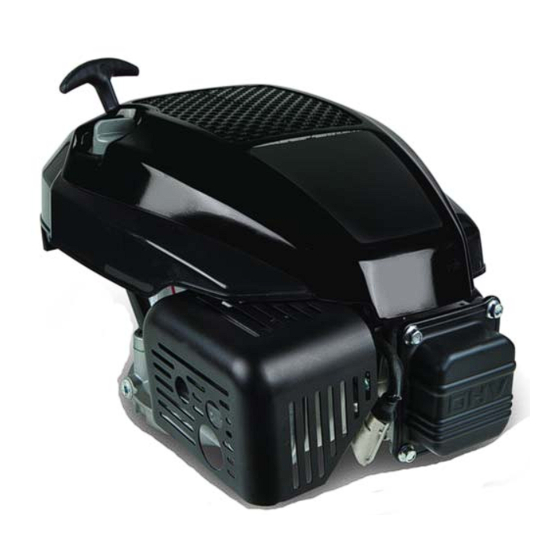
Professional Shop Manual
P71 Series Vertical Shaft Engines
NOTE: These materials are for use by trained technicians who are experienced in the service and repair of outdoor power
equipment of the kind described in this publication, and are not intended for use by untrained or inexperienced individuals.
These materials are intended to provide supplemental information to assist the trained technician. Untrained or inexperi-
enced individuals should seek the assistance of an experienced and trained professional. Read, understand, and follow all
instructions and use common sense when working on power equipment. This includes the contents of the product's Oper-
ators Manual, supplied with the equipment. No liability can be accepted for any inaccuracies or omission in this publication,
although care has been taken to make it as complete and accurate as possible at the time of publication. However, due to
the variety of outdoor power equipment and continuing product changes that occur over time, updates will be made to these
instructions from time to time. Therefore, it may be necessary to obtain the latest materials before servicing or repairing a
product. The company reserves the right to make changes at any time to this publication without prior notice and without
incurring an obligation to make such changes to previously published versions. Instructions, photographs and illustrations
used in this publication are for reference use only and may not depict actual model and component parts.
© Copyright 2013 MTD Products Inc. All Rights Reserved
MTD Products Inc. - Product Training and Education Department
Advertisement
Table of Contents
Troubleshooting

Subscribe to Our Youtube Channel
Related Manuals for MTD P71 Series


Summary of Contents for MTD P71 Series
- Page 1 Instructions, photographs and illustrations used in this publication are for reference use only and may not depict actual model and component parts. © Copyright 2013 MTD Products Inc. All Rights Reserved MTD Products Inc. - Product Training and Education Department...
-
Page 3: Table Of Contents
Table of Contents Chapter 1: Introduction Professional Service Manual Intent ..............1 Safety ........................ 1 Fasteners ......................3 Assembly instructions ..................3 Model and serial number .................. 5 Maintenance ..................... 5 Spark plugs ....................... 6 Air filter ......................7 Oil type and capacity..................8 Changing the oil .................... - Page 4 Chapter 4: The Fuel System and Governor Fuel Line ......................37 Inspect the fuel lines ..................37 Inspecting the fuel ................... 38 Test fuel for alcohol ..................38 Fuel filter ......................39 The fuel tank ....................40 Evaporative (EVAP) emissions system ............41 Troubleshooting the EVAP system ..............
- Page 5 Chapter 8: Exhaust Muffler ......................79 Exhaust manifold .................... 80 Chapter 9: Cylinder Head Cylinder Head Removal ................... 81 Valves ......................84 Push rod guides ....................86 Chapter 10: Crankshaft, piston and Connecting Rod Engine Dis-assembly ..................87 Crank shaft inspection ..................91 Piston Inspection .....................
-
Page 7: Chapter 1: Introduction
• Common sense in operation and safety is assumed. • In no event shall MTD be liable for poor text interpretation or poor execution of the procedures described in the text. • If the person using this manual is uncomfortable with any procedures they encounter, they should seek the help of a qualified technician or MTD Technical Support. - Page 8 P71 Series Vertical Shaft Engines • Be prepared in case of emergency: ! CAUTION ! CAUTION Keep a fire extinguisher nearby Keep a first aid kit nearby Keep emergency contact numbers handy • Replace any missing or damaged safety labels on shop equipment.
-
Page 9: Fasteners
Introduction Fasteners • Most of the fasteners used on the MTD engine are metric. Some are fractional inches. For this reason, wrench sizes are frequently identified in the text, and measurements are given in U.S. and metric scales. • If a fastener has a locking feature that has worn, replace the fastener or apply a small amount of releas- able thread locking compound such as Loctite®... - Page 10 P71 Series Vertical Shaft Engines MTD Vertical Engine Model Designators 1 P 6 1 M U A Major Revision Starter/Alternators 1=Recoil start Change 2=Electric start (12V) 3=E. start/alt. 18W 4=E. start/alt. 3A/5A 5= AutoChoke/ Recoil Compliance 6= AutoChoke/Electric Start 7= AutoChoke/Electric Start/Alt...
-
Page 11: Model And Serial Number
Introduction Model and serial number The model and serial number can be found on a white sticker with a bar code. The sticker is located behind the dipstick. See Figure 1.1. Model /serial number Dipstick Figure 1.1 NOTE: The serial number will always start with the model number. Maintenance The recommended maintenance intervals listed in this manual are a guideline. -
Page 12: Spark Plugs
Cleaning the spark plug: NOTE: MTD does not recommend cleaning spark plugs. Use of a wire brush may leave metal deposits on the insulator that causes the spark plug to short out and fail to spark. Use of abrasive blast for cleaning may cause damage to ceramic insulator or leave blast media in the recesses of the spark plug. -
Page 13: Air Filter
Introduction Air filter To remove/replace the air filter: Rotate the air filter housing counter clockwise, approximately a quarter turn. See Figure 1.3. Pull the housing off of the engine. Figure 1.3 Remove the air filter and foam pre-cleaner. Figure 1.4. Inspect the air filter and foam pre-cleaner. -
Page 14: Oil Type And Capacity
P71 Series Vertical Shaft Engines Oil type and capacity The recommended oil for MTD engines is an SAE 30 oil with an SM API rating or better. The oil capacity is 17.0- 20.3 fl.oz (0.5-0.6 liters). • Check the oil level daily and change the oil more frequently in severe operating conditions such as high ambient temperature, dusty conditions, or high load use in exceptionally thick grass. - Page 15 Introduction To check the oil: Fully seat the Twist and remove the dipstick from the engine. dip stick before reading it Clean the oil off of the tip of the dipstick. Re-insert the dipstick and turn it until it is fully seated to get the oil level reading.
-
Page 16: Changing The Oil
There are three methods of changing the oil. The application the engine is mounted to will determine which method to use: NOTE: There are four ways to drain the oil out of the P71 series of engines: • Drain plug in the bottom of the sump. - Page 17 Introduction Tip the engine and application over Drain the fuel from the fuel tank into an approved container Remove the air filter. NOTE: Any time the engine is tipped, the fuel inside the carburetor will leak out into the air filter. Place an approved oil drain pan on the ground.
-
Page 18: Fuel System
If there are pieces of rubber on the barb of the fuel tank nipple, replace the affected fuel line. Fuel filter IMPORTANT: All MTD engines use low permeation fuel line to meet EPA guidelines. When replac- ing the fuel lines, they must be replaced with the same type of low permeation fuel line. -
Page 19: Valve Lash
Introduction Valve lash Valve lash is the clearance between the top of the valve stem and the rocker arm. The valve lash should be checked after the first 25 hours of use and every 100 hours after that. Valve lash can be checked and adjusted using the following steps:. - Page 20 P71 Series Vertical Shaft Engines Check valve lash between each valve stem and rocker arm using a feeler gauge. Intake valve lash (top valve) should be 0.004” - 0.006” (0.10 - 0.15 mm). See Figure 1.13. 0.005” feeler gauge Figure 1.13 Exhaust valve lash (bottom valve) should be 0.006”...
-
Page 21: Exhaust System
Introduction Exhaust system The exhaust system is a frequently overlooked component of an engine. It is important to make sure the muffler is in good condition and free of blockage. NOTE: A blocked muffler will result in poor performance. If a muffler is completely blocked, the engine may not start. - Page 22 P71 Series Vertical Shaft Engines Useful Engine Specifications Description Metric Engine displacement 11.9 cubic inch 195cc Spark plug gap 0.024” - 0.031” 0.6 - 0.8 mm Spark plug torque 177 - 221 in lbs 20 - 25 Nm Ignition module air gap 0.004”...
-
Page 23: Chapter 2: Basic Troubleshooting
Also check attachments for damage and make sure they are firmly mounted. Steps to troubleshooting NOTE: The steps and the order of the steps that follow are a suggested approach to troubleshooting the MTD engine. The technician does not necessarily have to follow them as described in this chapter. - Page 24 P71 Series Vertical Shaft Engines IV. Unusual exhaust tone There are tools that the technician can use in order to define the problem, such as: Interview the customer. 1a. Get a good description of their complaint. 1b. If it is an intermittent problem, verify what conditions aggravate the problem as best as possible.
-
Page 25: Identify Factors That Could Cause The Problem
ASIC ROUBLESHOOTING Identify factors that could cause the problem This is the second step in the troubleshooting process. Crankshaft will not turn. A. Starter not working. This can be an electrical failure or a mechanical failure. The likely suspects are: A dead battery. - Page 26 P71 Series Vertical Shaft Engines Run the engine with a spark tester in-line between the spark plug wire and the spark plug or use an oscilloscope and see if the spark goes away at the same time the engine dies.
- Page 27 ASIC ROUBLESHOOTING V. Makes unusual smoke when running a. Black smoke, usually heavy, usually indicates a rich air fuel mixture • Not enough air: air flow blockage or a partially closed choke. • Too much fuel: carburetor float or float valve stuck or metering / emulsion issues with the car- buretor.
- Page 28 P71 Series Vertical Shaft Engines chirping noise. • Confirm with a compression test and leak-down test. e. Unusual exhaust tone Splashy or blatty • Splashy idle usually indicates a slight rich condition. • May indicate an exhaust blockage, usually slightly muffled.
-
Page 29: Repairing The Problem
ASIC ROUBLESHOOTING Repairing the problem The third step in the troubleshooting process is to repair the problem. This step consists of: A. Form a diagnosis by using all of the information gathered from the troubleshooting that was performed. B. Physically perform the repair. The fourth, and hopefully final, step in the troubleshooting process is the follow through. -
Page 30: Prime Test
P71 Series Vertical Shaft Engines Prime test To perform a prime test: Prime the engine through the carburetor throat using a squirt bottle, filled with clean fresh gasoline. Make sure the throttle is in the run position. Attempt to start the engine. - Page 31 ASIC ROUBLESHOOTING Attach the leak down tester to an air supply of 90 psi. Adjust the tester until the gauge’s needle is pointing to the set position. Connect the tester to the adapter. NOTE: If the engine rotates it was not at top dead center.
-
Page 32: Compression Test
P71 Series Vertical Shaft Engines Compression test To perform a compression test: NOTE: Compression should be in the range of 55 - 80 PSI (3.8 - 5.5 Bar). • Disconnect the high-tension lead from the spark plug and ground it well away from the spark plug hole. -
Page 33: Pcv Testing
Figure 2.5. NOTE: A typical reading, under no load, is around -10” (-25.4cm) of water. NOTE: Experimentation by MTD’s Training and Education Department has revealed the following character- istics of MTD engines: • A leaky PCV system will not build-up substantial case pressure. -
Page 34: Troubleshooting Flow Charts
P71 Series Vertical Shaft Engines Troubleshooting flow charts Ignition Troubleshooting Engine runs Engine will erratically or shuts not start off, restarts Check for spark Spark No Spark Replace spark plug Check for the correct spark plug Isolate engine from equipment and repeat... -
Page 35: Engine Operation Problems
ASIC ROUBLESHOOTING Engine Operation Problems ENGINE KNOCKS OVERHEATS Associated equipment loose or Excessive engine loading improperly adjusted Check for excessive carbon in Low oil level or wrong viscosity oil combustion chamber Cooling air flow obstructed or Loose flywheel examine key, key way and proper flywheel nut torque clogged cooling fins Ignition timing or... - Page 36 P71 Series Vertical Shaft Engines Engine Operation Problems SURGES OR RUNS UNEVENLY EXCESSIVE OIL CONSUMPTION Fuel cap vent obstructed Oil level above full Dirty carburetor or air filter Wrong viscosity oil Carburetor improperly adjusted Excessive engine speed Governor sticking, binding or...
- Page 37 ASIC ROUBLESHOOTING Engine Operation Problems ENGINE VIBRATES ENGINE MISFIRES EXCESSIVELY Carburetor improperly adjusted Bent crankshaft Attached equipment out Wrong or fouled spark plug of balance Valves sticking or not Loose mounting bolts seating properly Ignition timing or If applicable counter balance not incorrect spark plug properly aligned Excessive carbon build up...
- Page 38 P71 Series Vertical Shaft Engines Engine Operation Problems LACKS POWER BREATHER PASSING OIL Oil level too high Air intake obstructed Lack or lubrication or improper Excessive RPM or improper lubrication governor setting Damaged gaskets, seals Carburetor improperly adjusted or "O" rings...
-
Page 39: Chapter 3: Air Intake System
NTAKE YSTEM CHAPTER 3: AIR INTAKE SYSTEM Air filter To remove/replace the air filter: Rotate the air filter housing counter clockwise, approximately a quarter turn. See Figure 3.1. Pull the housing off of the engine. Figure 3.1 Remove the air filter and foam pre-cleaner. See Figure 3.2. -
Page 40: Carburetor Removal/Replacement
P71 Series Vertical Shaft Engines Carburetor removal/replacement To remove/replace the carburetor: Remove the shroud by following the procedures described in Chapter 6: Starters. NOTE: Replace the fuel cap to minimized fuel spill- age. Remove the air filter by following the procedures described in the previous section of this chapter. - Page 41 12. Drain the fuel into an approved container. 13. Remove the fuel line from the fuel tank and discard it. Paint mark NOTE: MTD uses low permeation fuel lines to meet EPA Mounting nuts Calibration code guidelines. Low permeation fuel lines are made Figure 3.6...
-
Page 42: Intake Manifold
P71 Series Vertical Shaft Engines Intake manifold To avoid personal injury or property damage, use extreme care in handling gasoline. Gaso- ! WARNING ! WARNING line is extremely flammable and the vapors are explosive. Serious personal injury can occur when gasoline is spilled on yourself and/or your clothes which can ignite. Wash your skin... -
Page 43: Chapter 4: The Fuel System And Governor
Carburetor and insulator block NOTE: When working on the fuel systems, look at the whole system. A problem will rarely be isolated to one component. Fuel Line MTD uses GREENBAR fuel line. This is a multi- NBR intermediate layer NBR inner liner layer fuel line that meets the current EPA guidelines. -
Page 44: Inspecting The Fuel
This results in less power for the engine. A 10% ethanol (E10) mix is acceptable for MTD engines. Anything higher than that will result in perfor- Figure 4.2 mance issues. -
Page 45: Fuel Filter
If there are pieces of rubber on the barb of the fuel tank nipple, replace the affected fuel line. Fuel filter IMPORTANT: All MTD engines use low permeation fuel line to meet EPA guidelines. When replac- ing the fuel lines, they must be replaced with the same type of low permeation fuel line. -
Page 46: The Fuel Tank
P71 Series Vertical Shaft Engines The fuel tank When working around the fuel ! WARNING ! WARNING system, do not bring any sources of heat, spark, or open flame near the work area. Nuts To remove the fuel tank: Siphon the fuel out of the fuel tank into an approved container. -
Page 47: Evaporative (Evap) Emissions System
YSTEM AND OVERNOR Evaporative (EVAP) emissions system NOTE: All gasoline powered engines built on or after Jan- Charcoal canister uary 1, 2012 must meet Phase III emissions. Phase III emissions requires that the engine have Vacuum line an evaporative emissions system to limit the amount of fuel vapors that escape into the atmo- sphere. -
Page 48: Troubleshooting The Evap System
P71 Series Vertical Shaft Engines Troubleshooting the EVAP system Symptom Cause Fuel leaking from the A blockage in the charcoal carburetor throat or canister or between the vents canister and the tank. Engine runs rich • A blockage in the line... -
Page 49: Autochoke
YSTEM AND OVERNOR Autochoke These engines are equipped with a temperature com- pensating auto choke. The autochoke system is similar to the old style air vane governors. When the engine is at rest a spring holds the choke in the closed position. Figure 4.11. -
Page 50: Temperature Compensator
P71 Series Vertical Shaft Engines To remove/replace the air vane: Remove the fuel cap and tether by unscrewing them. See Figure 4.6. Remove the fuel tank nut. Remove the screw that holds the fuel tank to the shroud using a 10 mm wrench. -
Page 51: Carburetors
YSTEM AND OVERNOR Carburetors Troubleshooting the carburetor is a process of elimination. If everything else on the engine checks out, the carbu- retor is probably bad. NOTE: It is important to perform a compression or leak down test before condemning a carburetor. An engine can have a borderline compression reading and not create enough of a vacuum to draw in a sufficient fuel/air charge. -
Page 52: Disassembly And Rebuilding The Carburetor
P71 Series Vertical Shaft Engines Disassembly and rebuilding the carburetor Clamp off the fuel line to prevent fuel spillage and disconnect it from the carburetor nipple Drain the fuel into an approved container. Remove and discard the fuel line. Float bowl Remove the carburetor by following the steps described in Chapter 3: Air Intake and Filter. - Page 53 YSTEM AND OVERNOR Remove the main jet by using a narrow-shank straight blade screwdriver. See Figure 4.20. NOTE: Fuel enters the central column through a port about 1/2” (1cm) from the bottom, to help prevent the ingress of any residue in the bottom of the bowl.
-
Page 54: Governor
P71 Series Vertical Shaft Engines Increase spring tension to Governor spring increase engine speed Adjust the top no-load speed by slightly bending the bracket that the governor spring connects to. The bracket is visible under the air filter. See Figure 4.23. - Page 55 YSTEM AND OVERNOR Governor arm To remove the governor arm from the governor shaft: Siphon the fuel out of the fuel tank into an approved container. Remove the oil dipstick. Remove the engine cover. Nuts Remove the 3 nuts that hold down the shroud. See Figure 4.25.
- Page 56 P71 Series Vertical Shaft Engines To install the governor arm: Rotate governor shaft counter clockwise until it stops. Attach the throttle linkage and governor spring. Position the governor arm over the governor shaft so that it is holding the throttle plate in the wide open position.
-
Page 57: Governor Shaft
YSTEM AND OVERNOR Governor shaft To remove or replace the governor shaft: Remove the engine from the unit. Remove the governor arm by following the proce- dures described in the governor arm section of this chapter. Remove the sump by following the steps described in Chapter 10: Disassembly. - Page 58 P71 Series Vertical Shaft Engines Remove the governor shaft seal. See Figure 4.32. Governor shaft seal Figure 4.32 Slide the governor shaft into the engine block from the inside of the engine. Seal Carefully slide a new seal over the governor shaft and seat using a 1/4”...
-
Page 59: Governor Cup, Gear And Oil Slinger
YSTEM AND OVERNOR Governor cup, gear and oil slinger The governor gear and cup are driven by the oil slinger gear. NOTE: The governor gear and cup are not serviceable. To remove/replace the oil slinger gear: Remove the engine from the unit. Remove the sump by following the steps described in Chapter 10: Disassembly. - Page 60 P71 Series Vertical Shaft Engines...
-
Page 61: Chapter 5: Lubrication
Lubrication CHAPTER 5: LUBRICATION Oil type and quantity The recommended oil for MTD engines is an SAE 30 oil with an SM API rating or better. The oil capacity is 17.0- 20.3 fl.oz (0.5-0.6 liters). 14°F 32°F 50°F 68°F 86°F 104°F... -
Page 62: Oil Dipstick
The oil level is determined by the highest point on the dipstick that is completely covered with oil. Figure 1.1 Dip stick tube removal Some MTD engines come with a dip stick tube, depending on the application. See Figure 5.2. To remove/replace the dip stick tube: Screw Remove the dip stick. -
Page 63: Lubrication System
Lubrication Lubrication system MTD uses a splash lube system for it’s vertical shaft engines. The oil slinger gear has paddles on it that “splashes” oil around the inside of the engine. See Figure 5.4. Slinger gear Paddles Figure 5.4 The splashing action will also atomize or change the oil into a mist. -
Page 64: Pcv
P71 Series Vertical Shaft Engines The PCV valve is located under the flywheel and allows PCV valve cover the crankcase pressure to escape. The function and test procedures for the PCV is covered in Chapter 2: Basic Troubleshooting. To service the PCV: Remove the flywheel by following the steps described in the Chapter 7: Ignition System. - Page 65 Lubrication Notch Insert a breather body, with the foam insert and a new O-ring. NOTE: There is a rib on the breather body that fits into a notch in the engine block. See Figure 5.10. Install the PCV valve cover with a new gasket. Tighten the cover screws to a torque of 62 - 80 in lbs.
- Page 66 P71 Series Vertical Shaft Engines...
-
Page 67: Chapter 6: Starters
Starters CHAPTER 6: STARTERS Engine shroud removal To remove recoil assembly from the engine: Remove the engine cover: NOTE: There are two types of engine covers: See Figure 6.1. • Full cover • Bib cover Full Figure 6.1 Full cover 1a. -
Page 68: Recoil Starter Removal/Replacement
P71 Series Vertical Shaft Engines Remove the oil dipstick. Remove the 3 nuts that hold down the shroud. See Figure 6.3. Nuts Figure 6.3 Remove the air filter by following the procedures described in Chapter 3: Air Intake System Disconnect the purge hose from the air filter base. -
Page 69: Starter Cup
Starters Starter Cup Starter cup Remove the recoil starter by following the procedures described int the recoil starter section of this chapter. Inspect the inside of the starter cup. See Figure 6.6. NOTE: If the starter was failing to engage the flywheel, and the edges of the teeth inside the cup are rounded, replace the starter cup. -
Page 70: Starter Rope
P71 Series Vertical Shaft Engines Starter Rope The most common failure mode for most recoil assem- blies is a broken rope. See Figure 6.8. Starter cord knot NOTE: If the spring was not damaged when the recoil sprung back, it is possible to simply remove the remnants of the old rope. - Page 71 Starters Rope-return tension may NOTE: If starter rope tension needs to be adjusted, there be increased by winding is room between the recoil housing and the pulley the rope and pulley to wind-on more tension. See Figure 6.11. counter clockwise. 10.
-
Page 72: Starter Pulley And Recoil Spring
P71 Series Vertical Shaft Engines Starter pulley and recoil spring The recoil spring is nested within the starter pulley and both parts are assembled as a single part number. Pressure plate Eye protection should be worn if ! CAUTION ! CAUTION Shoulder screw the starter pulley is to be removed. - Page 73 Starters NOTE: If the spring is undamaged, but has been removed from the pulley, the spring may be re-wound. Engage the hook in the end of the spring with the slot in the outer lip of the recess that the spring fits in, and wind the spring into the recess in a counter-clockwise direction.
-
Page 74: Electric Starter
P71 Series Vertical Shaft Engines Electric starter To remove/replace the electric starter: Remove the shroud by following the procedures described in the Engine Shroud Removal section of this chapter. Disconnect the starter harness. Remove the two nuts the hold the starter cover to the starter, using an 8 mm wrench. -
Page 75: Starter Interlock Switch
Starters Starter Interlock Switch On engines equipped with an electric starter, there is a Starter Interlock Switch mounted on to the engine brake assembly. The interlock switch prevents power from reach- ing the electric starter unless the safety bail is depressed Starter Interlock Switch or the engine brake is released. -
Page 76: Schematic
P71 Series Vertical Shaft Engines Schematic... -
Page 77: Chapter 7: Ignition System
Ignition System CHAPTER 7: IGNITION SYSTEM Troubleshooting the ignition system The purpose of the ignition system is to provide a spark in the combustion chamber at the proper time to efficiently ignite the fuel/air mixture. The steps in troubleshooting the ignition system are: Examine the spark plug(s) by following the steps described in the spark plug section of this chapter. -
Page 78: Troubleshooting The Stop Switch
P71 Series Vertical Shaft Engines Troubleshooting the stop switch To test the stop switch: Lead from stop switch Remove the engine shroud. Unplug the wire from the spade terminal on the module. Connect one probe of a Digital MultiMeter (DMM) to the lead disconnected from the module. -
Page 79: Troubleshooting The Flywheel
Ignition System Troubleshooting the flywheel To Troubleshoot the flywheel: Remove the engine shroud. NOTE: Failure of the magnets in the flywheel is exceed- ingly rare. Test the magnets by holding an item made of ferrous metal roughly 1/4” (.635cm) away from the magnets in the flywheel. -
Page 80: Spark Plug
P71 Series Vertical Shaft Engines Spark plug • The spark plug is a F6RTC, part #951-10292, gapped to 0.024” - 0.031” (0.6 - 0.8 mm). • Wear rate will vary somewhat with severity of use. If the edges of the center electrode are rounded-off, or any other apparent wear / damage occurs, replace the spark plug before operating failure (no start) occurs. -
Page 81: Ignition Module
Ignition System Ignition module The ignition system is a capacitive discharge ignition system, contained in a single module. • The capacitive discharge has a three leg design. • The magneto is energized by the passing of a pair of magnets mounted in the flywheel. •... -
Page 82: Engine Brake And Stop Switch (If Equipped)
P71 Series Vertical Shaft Engines Engine brake and stop switch (if equipped) NOTE: The stop switch and brake (for lawn mower applications) must be able to stop the blade from rotating within 3.0 seconds after the release of the safety bail, per ANSI B71.1- 2003 standard. -
Page 83: Flywheel
Ignition System Flywheel To remove the flywheel: Remove the recoil assembly and the engine shroud by following the steps described in Chapter 6: Starter. Lock the engine to prevent it from turning. Loosen the flywheel nut until it is a couple of threads past the end of the crank shaft using a 19mm wrench. - Page 84 P71 Series Vertical Shaft Engines Inspect the key, keyway, and tapered mating sur- faces of the flywheel and crankshaft. See Figure 7.16. NOTE: If the key is damaged it must be replaced. If there is damage to the crankshaft key way,...
-
Page 85: Chapter 8: Exhaust Muffler
Exhaust CHAPTER 8: EXHAUST Muffler The exhaust system is a frequently overlooked component of an engine. It is important to make sure the muffler is in good condition and free of debris and/or insects. NOTE: A blocked muffler will result in poor performance. If a muffler is completely blocked, the engine may not start. -
Page 86: Exhaust Manifold
P71 Series Vertical Shaft Engines Exhaust manifold To remove/replace the exhaust manifold: Remove the muffler by following the procedures described in the previous section. Remove the manifold screws using a 10 mm wrench. See Figure 8.3. Clean the cylinder head and muffler of any residual gasket material. -
Page 87: Chapter 9: Cylinder Head
Cylinder head CHAPTER 9: CYLINDER HEAD The Cylinder head of the MTD engine can be removed without removing the engine from the application. To remove the cylinder head: NOTE: If possible, it is recommended that the machine be positioned on the bench so that the cylinder head is vertical for removal. - Page 88 P71 Series Vertical Shaft Engines Loosen the jam screws and fulcrum nuts that secure the rocker arms using a 10mm wrench and a 14mm wrench. See Figure 9.3. Pivot the rocker arms aside, or remove them com- pletely, and remove the push rods.
- Page 89 Cylinder head 15. Position the cylinder head on the engine block. 16. Install the 5 head bolts, and tighten them to a torque of 221 - 239 in lb. (25 - 27 Nm) in 89 in lb (10 Nm) steps. See Figure 9.6. 17.
-
Page 90: Valves
P71 Series Vertical Shaft Engines Valves Valves and valve parts, like springs and keepers, are not available as service parts. The valves and valve seats can be serviced by grinding and lapping or the head can be replaced. Depending on local machine and labor costs, it is probably more economical to replace the cylinder head versus servicing the valves. - Page 91 Cylinder head Inspect the valve seat. See Figure 9.9. • Valve seats are 46 degrees. NOTE: This engine does not have the standard 3 angle cut. Seat angle is 46 • Seat width should be 0.044” - 0.054” (1.13 - 1.38 mm).
-
Page 92: Push Rod Guides
P71 Series Vertical Shaft Engines Push rod guides NOTE: The push rod guides are a wear item. On extreme cases, the guides can wear to a point that the push rods slip out from under the rocker arms. To remove/replace the push rod guides:... -
Page 93: Chapter 10: Crankshaft, Piston And Connecting Rod
The first step to disassemble the engine is to remove the engine from the application by following the steps described in the service manual for that particular application. NOTE: The MTD engine is NOT to be opened under warranty. If an internal engine failure occurs during the warranty period, replace the whole engine, no short blocks. - Page 94 P71 Series Vertical Shaft Engines Remove the sump bolts using a 10mm wrench. Carefully slide the sump off of the crank shaft. See Figure 10.2. Figure 10.2 Remove the camshaft. See Figure 10.3. NOTE: Align the timing marks to allow easier...
- Page 95 Crankshaft, piston and connecting rod Place a match mark here NOTE: Match mark the connecting rod cap and the con- necting rod so that they can be reassembled in the proper orientation. 20. Remove the connecting rod cap using a 7 mm wrench.
- Page 96 P71 Series Vertical Shaft Engines Lift up on crank shaft Remove the crank shaft. See Figure 10.8. Figure 10.8...
-
Page 97: Crank Shaft Inspection
Crankshaft, piston and connecting rod Crank shaft inspection Inspect the crank shaft journals for galling, scoring, Bearing contact pitting or any other form of damage. area Measure the journals at the bearing contact points using a vernier caliper or a micrometer. See Figure 10.9. -
Page 98: Piston Inspection
P71 Series Vertical Shaft Engines Piston Inspection Separate the piston from the connecting rod: Remove one of the piston pin clips. See Figure 10.11. Push the piston pin out of the piston. Slide the connecting rod out of the piston. - Page 99 Crankshaft, piston and connecting rod NOTE: The top ring is symmetrical and the middle ring has a tapered profile. The larger radius of the middle ring should face the crankshaft. See Figure 10.14. Top ring Middle ring 3 piece oil ring Figure 10.14 Piston ring end Top ring...
-
Page 100: Connecting Rod Inspection
P71 Series Vertical Shaft Engines Inspect the piston pin for galling, scoring, pitting or any other form of damage. Measure the piston pin using a vernier caliper or a micrometer. See Figure 10.17. Figure 10.17 Connecting rod inspection Inspect the connecting rod for cracks or any signs of Measure at right angles damage. -
Page 101: Cylinder Inspection
Crankshaft, piston and connecting rod Cylinder inspection Measure the cylinder bore Clean and inspect the cylinder, inside and out. NOTE: If there is any sign of damage, especially cracked cooling fins, short block the engine. NOTE: Take two measurements of the cylinder bore 90 degrees apart at the top, bottom and middle of the cylinder. -
Page 102: Bearings
P71 Series Vertical Shaft Engines Bearings There are two bearings to inspect; a plain bearing in the sump and a ball bearing in the cylinder block. To inspect the bearings: Remove the sump and cylinder block oil seals using Seal puller a seal puller. -
Page 103: Reassembly
Crankshaft, piston and connecting rod Reassembly Clean the cylinder Seal driver 1a. Remove all gasket material from all mating sur- faces. 1b. Clean the cylinder and sump. Oil seals 2a. Install a new oil seal in the cylinder block. See Figure 10.24. - Page 104 P71 Series Vertical Shaft Engines Tap piston with Tap the piston through the ring compressor hammer into the cylinder using a wooden hammer han- handle dle. See Figure 10.27. NOTE: Make sure the crankshaft journal is at BDC (bottom dead center) to prevent damage from the connecting rod.
- Page 105 Crankshaft, piston and connecting rod Install the cam shaft by: 6a. Pre-lube the cam shaft with clean 10W-30 Cam shaft motor oil or engine assembly lube. Timing marks 6b. Rotate the crank shaft until the timing mark points to the tappets. Insert the cam shaft while aligning the timing Compression marks.
- Page 106 P71 Series Vertical Shaft Engines Install the cylinder head by following the steps described in Chapter 9: Cylinder head. Install the muffler by following the steps described in Chapter 8: Exhaust. Install the flywheel and module by following the steps described in Chapter 7: Ignition system.
-
Page 107: Engine Specifications Chart
Crankshaft, piston and connecting rod Engine specifications chart Specification Minimum Maximum Displacement 11.9 cu. in (195 cc) Bore 2.7953” 71.001 2.7957” 71.011 Stroke 1.937” (49.2 mm) Module air gap 0.004” 0.10 0.020” 0.50 Spark plug gap 0.024” 0.60 0.031” 0.80 Intake valve lash 0.004”... -
Page 108: Engine Torque Values Chart
P71 Series Vertical Shaft Engines Specification Minimum Maximum Intake lobe base circle diameter 0.3905 9.92 0.3905 9.92 Exhaust lobe rise 0.197 5.00 0.203 5.15 Exhaust lobe base circle diameter 0.3905 9.92 0.3905 9.92 Compression ring end gap 0.006” 0.15 0.010”... - Page 109 Crankshaft, piston and connecting rod Fastener S.A.E. Metric Intake manifold at carburetor and 62 - 80 in lbs 7 - 9 Nm head Intake manifold at head 80 - 106 in lbs 9 - 12 Nm Intake manifold support stud 80 - 106 in lbs 9 - 12 Nm Module...
- Page 110 P71 Series Vertical Shaft Engines...
-
Page 111: Chapter 11: Failure Analysis
Failure Analysis CHAPTER 11: FAILURE ANALYSIS A properly maintained engine will provide years of service. Occasionally an engine will fail. An important part of working on engines is being able to recognize the root cause of engine failures. Was it something the customer did? Was it a manufacturing defect? Did the engine just wear out? All of these questions need to be answered. - Page 112 P71 Series Vertical Shaft Engines When particles enter the combustion chamber, the up and down motion of the piston grinds the parti- cles into the side of the cylinder walls and damages the cylinder wall, piston and piston rings. Scoring...
- Page 113 Failure Analysis Because the oil suspends the particles, the engine components that are immersed in oil will show defi- nite signs of abrasive ingestion especially around the connecting rod and main bearing journals. See Figure 11.5. NOTE: Abrasives that are trapped in the oil will cause the lower portion of the combustion chamber to wear- ing more than the upper portion.
-
Page 114: Insufficient Lubrication
P71 Series Vertical Shaft Engines Insufficient lubrication The bearing surfaces in an engine are not smooth. The machining processes used to make the engine parts, leave little peaks and valleys that are only visible under a microscope. These peaks are called asperities. As the engine breaks in, the asperities break off leaving plateaus that become the bearing surface. - Page 115 Failure Analysis Discoloration Metal transfer is the primary indicator that the film of oil between two engine parts has been violated. If the damage is localized, a general failure of the lubri- cation system is probably not the cause. As an example: a piston skirt shows metal transfer to the cylinder wall.
-
Page 116: Engine Over-Speed
P71 Series Vertical Shaft Engines Engine Over-speed The MTD engine is designed for a maximum speed of 3300 rpm. When the governor is unable to control the engine rpm, the engine can accelerate past the safe maximum speed. When an engine runs beyond its designed speed, a few things happen: As the piston moves up and down in the cylinder, it builds momentum. -
Page 117: Overheated
Overheated The MTD engines are air cooled engines. Because of this, cleanliness of the engine is very important to the life of the engine. Dirt, grass and sludge all form an insulating layer on the engine. This will trap the heat in the engine and cause it to over heat. -
Page 118: Mechanical Breakage/ Wear
P71 Series Vertical Shaft Engines Mechanical Breakage/ Wear Sometimes an engine fails because a part breaks. There are generally three causes of a broken part, outside of the previously discussed engine failures. They are abuse, wear, and manufacturing defects. Bent blade A very common sign of an abused engine is a bent crank shaft. - Page 120 MTD Products Inc - Product Training and Education Department FORM NUMBER - 769-09340 9/2013...
Need help?
Do you have a question about the P71 Series and is the answer not in the manual?
Questions and answers