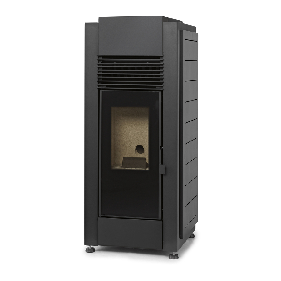
Page 1
Wood Pellet Stove Instruction Manual English Models Alpes 8 kW | Alpes 10 kW Douro 17 kW | Douro 23 kW Read these instructions carefully before installing, using and servicing the unit. The product is supplied with this instruction manual.
Page 2
* The Free Standing Pellet Fires are manufactured in compliance with the EN 14785:2008 Standards * SOLZAIMA bears no responsibility for any damage to the unit if it is installed by non-qualified personnel; * SOLZAIMA is not responsible for any damage to units not installed and used in compliance to the instructions included in this manual;...
Contents Package content ......................3 1.1. Unpacking the free standing fire ................3 Safety precautions ......................4 2.1. For your safety, we recommend that: ..............5 Technical specifications ....................7 Installation of the free standing pellet fire unit .............. 11 8.1.
Page 4
Humidifier (only in the Alpes models) ................47 Installation of the optional UPS connection Safety Kit ..........48 Maintenance ....................... 50 Alarms / failures / recommendation list ............... 61 Installation diagrams (only backboiler models – Douro 17kW and Douro 23kW) ..63 17.1.
Page 5
Solzaima Solzaima's vision has always been to provide the cleanest, renewable and more cost- effective energy. This is why for more than 35 years we've been dedicated to manufacturing biomass heating units and solutions. As a result of the persistence and unconditional support from a network of partners, Solzaima is currently the leader in biomass heating units manufacturing, especially with its range of central heating units with backboilers and free standing pellet fires.
1. Package content Solzaima ships the unit with the following components: - Free standing pellet fire model Alpes 8 kW, Alpes 10 kW, Douro 17kW or Douro 23 kW - Side covers, top front cover and bottom front cover - Instruction Manual...
Figure 1 – Unpacking the free standing fire unit 2. Safety precautions Solzaima is not liable for any damages to the unit if the specified precautions, warnings and operating procedures are not followed. Units manufactured by Solzaima are easy to operate and special attention was given to their components in order to protect users and installers against accidental damages.
2.1. For your safety, we recommend that: Make sure you fully read and understand this instruction manual before using the free standing pellet fire as a biomass heating unit. Make sure that the hydraulic circuit was correctly assembled and connected to the water supply before turning on the free standing pellet fire (only in water models –...
Page 9
Solzaima offers you an optional safety system which allows the Free Standing Fire unit to be connected to a UPS so that during any power failure the fume extractor will still operate until complete extraction of all the fumes;...
3. Technical specifications Alpes Alpes Douro Douro FEATURES Units 10kW 17kW 23kW Weight 1110 1150 1200 Height Width Depth Diameter of the fume discharge pipe Reservoir capacity Maximum heating capacity m³ 15,1 / 1,9 20,4 / 2,6 Maximum overall thermal power (fire insert/backboiler) 6,0 / 0,9 8,9 / 1,5...
Page 11
Front Rear Side Figure 2 – Dimensions of the free standing pellet fire unit (air model – Alpes 8 kW) Front Rear Side Figure 3 – Dimensions of the free standing pellet fire unit (air model – Alpes 10 kW)
Page 12
Front Rear Side Figure – Dimensions of the free standing pellet fire unit (backboiler model – Douro 17 kW) Front Rear Side Figure 5 – Dimensions of the free standing pellet fire unit (backboiler model – Douro 23 kW)
Page 13
Figure 6 – Hydraulic connections of the free standing pellet fire unit (backboiler model – Douro 17 Figure 7 – Hydraulic connections of the free standing pellet fire unit (backboiler model – Douro 23...
4. Installation of the free standing pellet fire unit Before installing, please perform the following steps: Upon reception, check the product for completeness and to determine that is does not show any damage signs. Any damages or defects should be checked before the unit is installed.
4.1. Assembly of removable parts After the installation, the Free Standing Fire unit should be fitted with the removable covers. Air model - Alpes 8kW and Alpes 10kW - Top front cover The following figure shows how to assemble the top front cover. First, remove the two screws located at the top of the unit (Figure 9-a).
Page 16
Figure 9 – Assembly of the top front cover of the unit - Bottom front cover To assemble the bottom front cover, remove the screws on the unit (Figure 10-1 and b). Then apply the part (Figure 10-c), by fitting the existing lower notch into the groove on the unit.
Page 17
- Side covers To install the unit's side covers position the covers and insert them as illustrated, onto the existing supports. Figure 11 – Assembly of side covers - Humidifier The humidifier is located inside the unit, together with other components (Figure 12-a). Remove it and install it in the correct location on the top of the unit (Figure 12-b) and then attach the respective lid (Figure 12-c).
Page 18
Backboiler model - Douro 17kW and Douro 23kW - Top front cover To install the top front cover, place it over the unit (Figure 13-a) and then tighten the screws that secure it to the top panel of the unit (Figure 13-b). Figure 13 –...
4.2. Installation requirements The minimum distance between the free standing pellet fire unit and particularly flammable surfaces is specified in Figure 15. The top of the unit must be at least 100cm separated from the ceiling, especially in rooms with ceilings consisting of flammable materials. The base supporting the unit cannot be made of combustible material (e.g.
As indicated in Figure 15, the exhaust pipe must be assembled so as to allow cleaning and maintenance of the pipe by inserting inspection points. Under normal operating conditions, the combustion gas flow should create a draught of 12 Pa one meter above the chimney neck. ...
Page 21
Figure 16 – Side view of the installation without a chimney, illustrating the inspection point.
Page 22
Figure 17 – Examples of standard installations.
Page 23
Failure to comply with these requirements may prevent the correct operation of the unit. Follow all the instructions presented on the diagrams. The Alpes and Douro units operate with the combustion chamber in vacuum, so it is absolutely necessary to have a fume exhaust pipe to extract combustion gases properly. Fume duct material: The tubing must consist of 0.5 mm thick rigid stainless steel, with fastening joints attaching the different sections and accessories.
4.5. Installation with a chimney As shown in Figure 18, the unit is installed with an exhaust pipe ( 80 mm for the air model; 100 mm for the backboiler model) directly on to the chimney. If the chimney is too large, an 80 mm-wide pipe should be installed at the fume outlet. A T-tube must be attached to the base of the pipe to allow for periodic inspection and annual maintenance, as illustrated in Figure 18.
4.6. Hydraulic Installation (only for the backboiler model) * The chapter 13 (installation diagrams) contains the optional connection diagrams for central heating installations, with or without water heating for household use; * The free standing pellet fire unit is equipped with a circulating pump, an expansion vessel (6 litre volume (in the Douro 17kW model) or 10 litre volume (in the Douro 23kW model) and a 3 bar safety valve;...
5. Fuel The free standing pellet fire unit must be operated exclusively with pellets. No other fuel may be used. Use only pellets certified by standard EN 14961-2 grade A1, with a 6 mm diameter and measuring between 10 and 30 mm. The pellets may have a maximum humidity of 8% their weight.
6. Use of the Free Standing Pellet Fire Recommendations Before starting up the unit, please check the following: Guarantee that the unit is properly connected to the power mains using the 230VAC power cable. Figure 19 – Electric power plug. ...
The Free Standing Pellet Fire units have a probe for measuring the room temperature. This probe is attached to the grid on the rear panel (Figure 20). For a good reading of the room temperature, avoid the contact between the end of the probe and the unit chassis.
7.2. Remote control and display MODE MENU 20.5ºC 16:03 Figure 3 – Remote control and display toggle between b) Key to access menus and c) Key to start/stop the manual and automatic mode and confirmation key (ok). unit reset error exit menus (esc).
7.3. Display information summary 7.3.1. Menu Menu indicating that the unit power is "off", the room temperature in ºC and Time. MODE MENU 20.5ºC 16:03 Selecting the operation mode: to select the operation mode, press the “mode” key to select “Manu” for manual mode or “Auto” for automatic mode (only for the Alpes model). MODE MENU Mode:AUTO Menu...
Heating temperature To set the desired heating temperature press “set”. The display starts to flash. Press the “+” or “-“ key to select the desired temperature and then “ok” to confirm. Press the "+" key to go to the "Temperatura de sanitários" (Bathroom Temperature) menu. MODE MENU 85ºC...
Page 32
Minutes To set the minutes press “set”. The display starts to flash. Press the “+” or “-” key to select the desired minutes and then “ok” to confirm. Press the "+" key to go to the "Dia" (Day) menu. ...
Month To set the month press “set”. The display starts to flash. Press the “+” or “-” key to select the desired month and then “ok” to confirm. Press the "+" key to go to the "Ano" (Year) menu. ...
Page 34
Activation To activate the timer press “set”. The "Habilitação" (Activation) menu appears. The timer may only be activated after setting the configurations, as shown in the following paragraph. To activate the timer mode press “set”. The display starts to flash. Press the “+” or “-” key to select "On"...
Page 35
MODE MENU < Prog. 1 > Press "set" again and when the display starts to flash, press "+" or "-" to select "On" or "Off". Press "ok" to confirm the selection. Press the "+" key to go to the "P1 A. Inicio" (P1 A.
Page 36
To set the set point room temperature in Programme P1, press “set”. The display starts to flash. Press the “+” or “-” key to select the desired temperature and then “ok” to confirm. Press the "+" key to go to the "P1 Temp. Ar" (P1 Water Temp.) menu. To set the water set point temperature (only for the backboiler model) of Programme P1, press “set”.
Repeat the above steps for programmes P2 to P6. Note: After setting up the programmes, please remember to activate them on the "Habilitações" (Activation) menu. 7.3.5. Sleep The "Sleep" menu allows you to setup the time you want the unit to turn off. MODE MENU SLEEP...
Page 38
Language To select the language, press “set”. Using the “+” or “-” keys, select the desired language (Pt – Portuguese; Nl – Dutch; Gr – Greek; It – Italian; En – English; Fr – French; Es – Spanish; De – German). Press "ok" to confirm. Press the "+"...
Page 39
MODE MENU < > Lighting To select lit screen, press “set”. The display starts to flash. Press the "+" or "-" key to select the time at which you want the screen to light up, or choose "On" to keep the light on at all times.
Page 40
Pellet quantity Press "set" to see the "Actuações transitórias" (Temporary settings) menu. - Temporary settings This feature allows you to increase or decrease by 25% the amount of pellets at start- up. Press "set". The display starts to flash. Press "+" or "-" to increase or decrease (between -5 to +5), accordingly.
Page 41
Thermostat This feature allows you to enable or disable the room temperature thermostat. Press “set”. The display starts to flash. Press the “+” or “-” key to select "On" or "Off" and then “ok” to confirm. Press the "+" key to go to the "Carga Pellet" (Pellet loading) menu. ...
The technical menu is not available to the end user since it includes exclusively factory settings that must never be changed. 7.3.7. User Info This menu contains some user information regarding the Free Standing Fire unit. Press "set"; the "Código de Ficha" (File Code) menu appears. Display software/firmware code Press the "+"...
Page 43
Fume extractor operating speed (rotation per minute). Airflow measured by the air probe. Fume temperature. Worm drive rotation time ("On"). Ventilation power level.
Hydraulic circuit pressure 8. Start-up To start operating the Free Standing Pellet Fire unit, press the start/stop button for 3sec. The display should indicate "Acendimento" (Lighting) until the completion of this phase. The pellets will pass through the supply channel to the burning basket (combustion chamber), where they will be ignited using a heat resistor.
8.1. Stop The stop sequence of the unit is started by pressing the start/stop key for 3sec. Until this phase has been completed, the display will show “desactivação" (Disabling). The extractor will remain active until the fume temperature of 104ºF (40ºC) is reached, to guarantee that all the material has been burnt.
Figure 25 – Opening the lid 8.4. Filling the pellet reservoir 1 – Open the pellet reservoir lid at the top of the unit, as shown in Figure 25. 2 – Pour the pellets into the reservoir, as shown in Figure 26. Figure 26 –...
Page 47
thermostat). Note: the remote control is usually accompanied by a manual. To use the remote control, you must install an interface (Figure 27–b). Figure 27 – Remote control (programmable thermostat) and connection interface – both not included. For wireless remote controls, both wires must be connected, as indicated in the following figure: Colour codes: Gr –...
Figure 29 – Connection of the wired remote control 8.5.1. Instructions for remote control assembly 1 – Turn off the unit at the power switch, remove both the right side cover of the free standing pellet fire unit (Figure 30-a) and the plate with the microjoints (Figure 30-b). 2 –...
Page 49
4 – Connect the wires on the ON/OFF connector contact ( Figure 30-f); direct the wires through the cable gland to the interior of the unit (Figure 30-g); 6 – Assemble the interface at the appropriate location on the unit and position the remote control (On/Off contact) switch to "remote"...
Figure 4i – Installation of programmable thermostat 9. Humidifier (only in the Alpes models) Over time, the use of this type of heating equipment makes the air in the room or rooms where it is located tend to become very dry. To prevent this, the unit is equipped with a stainless steel container that can be filled with water to moisten the air through evaporation, as shown in the following figures.
10. Installation of the optional UPS connection Safety Kit Figure 32 – a) example of UPS (not included in the kit); b) UPS kit components To connect the kit to a UPS, proceed as shown in the following figures. First, remove the side cover to access the electronic plate (Figure 39-a). Then, assemble the UPS electronic module near the unit's electronic plate with the correct wires connected to the plate (Figure 33-b and c).
Page 52
Figure 33 – Installation of the UPS kit...
11. Maintenance The Solzaima free standing pellet fire unit requires careful maintenance. The most important thing is to remove the ash from the pellet burning area at regular intervals. This can be easily done by using a simple household vacuum cleaner. It should be cleaned after burning approximately 30kg (air model) / 60kg (backboiler model) of pellets.
Page 54
Figure 35 – a) Grid; b) Burning basket Figure 36 – Ash basket Figure 6 – Cleaning the burning basket...
Page 55
Figure 38 – Cleaning the interior of the unit Backboiler Model To perform maintenance on the backboiler model, clean the airflow pipes. To do this, raise the lid on the top of the unit (Figure 39-a) and then turn (Figure 39-b) and lift the levers inside several times (Figure 39-c) to make the dirt accumulated inside the pipes fall out.
Page 56
Then clean the inside of the unit using a steel brush on the surfaces where dirt has accumulated (Figure 40). Figure 40 – Cleaning the interior of the backboiler model The burning basket (Figure 41-a) and ash basket (Figure 41-b) must then be removed and the ash vacuumed from both. The interior of the unit must also be cleaned by opening the hatch, as shown in Figure 38.
Page 57
Air model – Alpes 8 kW For the Alpes 8 kW free standing pellet fire model, remove the side covers to access the side lids of the combustion chamber. To clean the interior of the unit, remove the screws (Figure 44-a), remove the lid and vacuum the ashes (Figure 45-a).
Page 58
Figure 44 – a) Remove the screws; b) Remove the lid Figure 45 – a) Vacuuming the interior ; b) Cleaning with a brush If fumes are not being extracted in the best manner possible, we recommend you clean the extractor by vacuuming it (Figure 46). However, we recommend that you perform this procedure at least once a year.
Page 59
Air model – Alpes 10 kW For the Alpes 10 kW free standing pellet fire model, remove the side covers to access the side lids of the combustion chamber. To clean the interior of the unit, unscrew the wing nuts (Figure 47) remove the lid and vacuum the ash (Figure 48-a). Using a 20- 25mm wide and 80cm long steel brush, clean the fume ducts (Figure 48-b).
Page 60
Figure 49 – a) Remove the screws; b) Remove the extractor Figure 50 – a) Vacuum the extractor shell; b) Vacuum the extractor Backboiler Model For the backboiler unit, the procedure involves cleaning the air flow pipes and turbulators. To do this, open the lid on the top of the unit (Figure 51-a) and remove the six wing nuts securing each turbulator set (Figure 51-b and 51-c).
Page 62
Figure 51 – Cleaning the air flow pipes and turbulators If fumes are not being extracted in the best manner possible, we recommend you clean the extractor as shown in Figures 52 and 53. However, we recommend that you perform this procedure at least once a year.
Page 63
Cleaning the glass The glass may only be cleaned with the unit completely cold, and using an appropriate product, as per the instructions for use. You should prevent the product from reaching the sealing ring and painted metal parts so that no undesirable oxidation occurs. The sealing ring is glued, so should not be exposed to moisture from water or cleaning products.
12. Alarms / failures / recommendation list Alarm Code Troubleshooting - the worm drive channel is empty - restart the unit Maximum time 2400 - resistance burnt – replace resistance Ignition failure - the burning basket has been incorrectly installed Temperature under: - 104ºF (40°C) (air No flame or lack of pellets...
Page 65
- Failures Failures Maintenance Air probe failure Low pellet level The door is open Air temperature probe failure Water temperature probe failure Water pressure sensor fault Water pressure close to being outside operating range Table 3 – List of failures Important note: the failures do not case the machine to shut down Warning! In case of an emergency, shut the unit down following the normal procedure to switch the...
13.4. Installation diagram for central heating and household water heating using a cylinder thermostat Figure 59 – Installation diagram for central heating and household water heating using a cylinder thermostat...
Solzaima makes all efforts to learn and to know the national forest park while efficiently responding to energy demands, taking permanent care to maintain its biodiversity and...
18. Glossary Ampere (A): SI unit of measurement of electric current bar: unit of pressure equal to exactly 100,000 Pa. This pressure is very close to standard atmospheric pressure. cal (Calorie): equal to the amount of heat required to increase the temperature of one gram of water by one degree centigrade.
Page 75
mA (milliampere): unit of measurement of electric current. Pa (Pascal): standard IS unit of pressure and tension. This unit is named after Blaise Pascal, eminent French mathematician, physicist and philosopher. Net heating value: also known as specific combustion heat. It represents the amount of heat released when a certain amount of fuel is completely burned.
19. Warranty All SOLZAIMA free standing pellet fire units have a 2 (two) year warranty from the date the invoice was issued. In order for your warranty to be valid, you must keep the invoice or receipt of purchase throughout the warranty period.
20. Annexes Operations flow charts Flow chart 1 – Normal activation Note (only for the backboiler model): The circulating pump operates intermittently from the moment the water temperature reaches 50ºC and operates continuously from the set-point temperature.
Page 79
Flow chart 2 - Disconnecting the machine Note (only for the backboiler model): The circulating pump is turned off when the water temperature reaches below 40ºC.
Need help?
Do you have a question about the Alpes 8 kW and is the answer not in the manual?
Questions and answers