Table of Contents
Advertisement
Available languages
Available languages
Quick Links
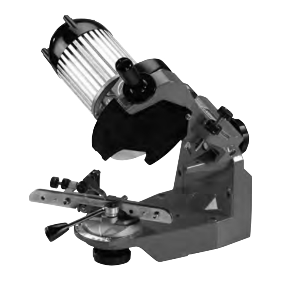
Bench Chain Grinder
510A
w w w. o r e g o n c h a i n . c o m
120 V~ 60 Hz
!
EN
1
FR
6
ES
11
Bench chain grinder
Meuleuse électrique pour chaînes de scie à moteur
Esmeriladora eléctrica para cadenas de motosierra
OWNER'S MANUAL
MANUEL D'UTILISATION ET ENTRETIEN
MANUAL DE INSTRUCCIONES
Attention: do not use the grinder before you have
Attention : ne pas utiliser l'appareil sans avoir
Atención: no utilice la unidad sin haber leído el
read the owner's manual in full
préalablement lu le manuel d'utilisation et entretien
manual de instrucciones
P00801078_R02_510A_U&M_OR_120V.indd 1
26/02/2009 18.04.18
Advertisement
Table of Contents

Related Manuals for Oregon 510A


Summary of Contents for Oregon 510A
- Page 1 Bench Chain Grinder 510A w w w. o r e g o n c h a i n . c o m 120 V~ 60 Hz Bench chain grinder Meuleuse électrique pour chaînes de scie à moteur Esmeriladora eléctrica para cadenas de motosierra OWNER’S MANUAL...
- Page 2 P00801078_R02_510A_U&M_OR_120V.indd 2 26/02/2009 18.04.18...
-
Page 3: Safety Rules
INTRODUCTION 15 - CHECK THE POSITION OF THE CABLE DURING OPERATION, making sure that it remains outside the range of action of the grinding wheel and is not under FOR YOUR OWN SAFETY READ INSTRUCTION MANUAL BEFORE tension. Never operate in the vicinity of other electrical cables. OPERATING GRINDER. -
Page 4: Warranty
TECHNICAL DATA grounding conductor to a live terminal. Check with a qualified electrician or service personnel if the grounding instructions Model 510A are not completely understood, or if in doubt as to whether the tool is properly Voltage 120V~ 60Hz grounded. -
Page 5: Installation
13. TESTING THE GRINDING WHEEL Hold the grinding wheel up by its central hole. Knock the edge of the grinding wheel FILE GUIDE P/N (fig.3) gently with a metal object. If it makes a numb non-metallic noise it means that the wheel could be damaged: do NOT use it! 16.1 INSTRUMENTAL MEASUREMENTS (FIG.13) 14. - Page 6 - At this stage, raise the arm and screw the knob P30, to move the cutter to be 24.1 RIGHT CUTTER VISE ROTATION (FIG. 20-21) sharpened further forwards. This forward movement corresponds to the quantity of material to be ground - Loosen the knob M20.
-
Page 7: Handling And Transport
30.4 HANDLING AND TRANSPORT - If you need to transport the machine, take it off the bench or wall, dismantle the grind- ing wheel and put all the parts in a packing box to protect them against impact. 30.5 DEMOLITION AND DISPOSAL The machine is to be demolished by qualified personnel in compliance with current laws in force in the country in which it is installed. -
Page 8: Mesures De Securite
INTRODUCTION 14 - N’UTILISEZ PAS LA MACHINE DANS DES ZONES DANGEREUSES. N’utilisez pas la machine dans des endroits humides ou sous la pluie. Il faut que la zone de POUR ÉVITER N’IMPORTE QUEL ACCIDENT, LISEZ CE MANUEL TRÈS travail soit bien éclairée. ATTENTIVEMENT AVANT DE DEMARRER L’AFFUTEUSE. -
Page 9: Garantie
équipé d’une prise similaire au modèle illustré dans le dessin A, équipé de la fiche de mise à la terre illustrée dans le dessin A. On peut utiliser Modèle 510A un adaptateur provisoire similaire au modèle illustré dans les dessins B et C pour Tension 120V~ 60Hz brancher la fiche à... - Page 10 12. FOURNITURE DE BASE (FIG.2) ÷ 2 TYPE DE CHAINE 1 - base 11 - rondelles pour vis M5 12 - vis M10x40 fixation bras 2 - groupe bras-moteur REFRENCE DE LA LARGEUR DE LA MEULE 3 - manuel d’utilisation et entretien 13 - rondelle pour vis M10 4 - carton de contrôle 14 - poignée arrêt bras...
-
Page 11: Recommandations Pour L'affûtage
21. MISE EN MARCHE 25.1 ANGLES D’AFFÛTAGE - Introduire la fiche du câble d’alimentation dans la prise de courant. - Après avoir établi le type de chaîne à affûter, établir les angles de réglage (étau et bras) en consultant le tableau des chaînes (colonnes A/C). 22. -
Page 12: Problèmes, Causes Et Solution
- Procéder au profilage de la meule en actionnant la machine et en éliminant le matériau 31. PROBLÈMES, CAUSES ET SOLUTION de la meule jusqu’à ce que soit obtenu un profil comme indiqué à la fig.38. Avant de procéder à quelque intervention que ce soit sur l’appareil, effectuer - Éteindre la machine une fois l’opération effectuée. - Page 13 muela y que nunca esté tenso. Nunca hacer funcionar la afiladora cerca de otros INTRODUCCIÓN cables eléctricos. POR SU PROPIA SEGURIDAD NO COMENZAR A TRABAJAR CON LA 16 - DIRECCIÓN DE CORTE. Apoyar la hoja o cortadora sobre el material de trabajo únicamente en el sentido contrario al de rotación de la hoja o cortadora.
- Page 14 B. Herramienta con cable y puesta a tierra para ser utilizado en un circuito de suministro con una tensión nominal menor a 150V~. Modelo 510A Esta herramienta esta diseñada para ser utilizada en un circuito que tiene un Tensión 120V~ 60Hz tomacorriente como el que se muestra en el dibujo A de la figura.
- Page 15 11. DESEMBALAJE con instrumentos o sea, utilizando plantilla y calibre. - Al final de este manual está la TABLA LISTADO DE LAS CADENAS. La esmeriladora se suministra parcialmente desmontada. Las columnas de esta Tabla contienen los siguientes datos: ÷ 2 12.
- Page 16 21. PUESTA EN FUNCIONAMIENTO 25. REGULACIÓN PARA EL ESMERILADO - Introduzca el enchufe del cable de alimentación, en la toma de corriente. Se debe esmerilar una cadena con el espesor del transportador (delimitador) idéntico al muestrario de cadena utilizado para la regulación precedente de la morsa. 22.
-
Page 17: Inconvenientes, Causas Y Soluciones
Mantenga bien firme el avivaesmeril con una mano (prestando atención para 31. INCONVENIENTES, CAUSAS Y SOLUCIONES no tocar el esmeril). Antes de realizar cualquier intervención en la unidad, realice las operaciones descriptas en el párrafo DETENCIÓN. - Realice el perfilado del esmeril mediante el accionamiento de la máquina y la extracción del material del esmeril hasta obtener un perfil como se muestra en la fig.38. - Page 18 GRINDING WHEEL GRINDING CHAIN TYPE GRINDING WHEEL P/N VISE ROTATE ANGLE HEAD TILT ANGLE WIDTH Oregon® Chain Part Number 11BC 5/16” 8.0mm OR534-516 35° 60° 5/16” 8.0mm OR534-516 30° 50° 3/16” 4.8mm OR534-316 35° 60° 18H & 18HX 3/16” 4.8mm OR534-316 35°...
- Page 19 DEPTH GAUGE DEPTH GAUGE P/N FILE SIZE FILE GUIDE P/N .060” 26800 5/16” 8.0mm .070” 107529 5/16” 8.0mm 107617 .050” 38850 7/32” 5.5mm 31686 .050” 38850 7/32” 5.5mm 31686 .025” 31941 3/16” 4.8mm 31690 .025” 31941 3/16” 4.8mm 31690 .025” 31941 5/32”...
- Page 20 9 14 Bench Chain Grinder PRO ECONOMY w w w. o r e g o n c h a i n . c o m 120 V~ 60 Hz Bench chain grinder Meuleuse électrique pour chaînes de scie à moteur Esmeriladora eléctrica para cadenas de motosierra OWNER’S MANUAL MANUEL D’UTILISATION ET ENTRETIEN...
- Page 21 (RH cutter) (LH cutter) 1/4” P00801078_R02_510A_U&M_OR_120V.indd 19 26/02/2009 18.04.45...
- Page 22 1/8” 3,2 mm RH CUTTER LH CUTTER CW ROTATION CCW ROTATION RH + LH CUTTERS 0° P00801078_R02_510A_U&M_OR_120V.indd 20 26/02/2009 18.04.51...
- Page 23 1/4” (6 mm) RH + LH CUTTERS 0° P00801078_R02_510A_U&M_OR_120V.indd 21 26/02/2009 18.04.59...
- Page 24 510A 120V~ - Spare parts_21/11/2008 Replacement Parts for the 510A Bench Grinder ItemNo. Part No. Description ItemNo. Part No. Description 109879 Switch, on/off 522687 Scale, arm turning 522637 Screw, height adjusting 35590 Spring, jaw 37947 End motor bell 109245 Knob (long), vise...
- Page 25 522638 105538 522637 534531 (120V~) - L=2000 mm 534478 522649 534553 534552 522687 534550 534549 534551 120V~ 60Hz P00801078_R02_510A_U&M_OR_120V.indd 23 26/02/2009 18.05.02...
- Page 26 NOTES P00801078_R02_510A_U&M_OR_120V.indd 24 26/02/2009 18.05.02...
- Page 27 NOTES P00801078_R02_510A_U&M_OR_120V.indd 25 26/02/2009 18.05.02...
- Page 28 NOTES P00801078_R02_510A_U&M_OR_120V.indd 26 26/02/2009 18.05.02...
- Page 29 NOTES P00801078_R02_510A_U&M_OR_120V.indd 27 26/02/2009 18.05.02...
- Page 30 NOTES P00801078_R02_510A_U&M_OR_120V.indd 28 26/02/2009 18.05.02...
- Page 31 P00801078_R02_510A_U&M_OR_120V.indd 29 26/02/2009 18.05.02...
- Page 32 U.S.A. Belgium BLOUNT EUROPE SA Oregon Cutting Systems Division OREGON ® CUTTING SYSTEMS GROUP outdoor products group Blount, Inc. RUE EMILIE FRANCQUI, 5 4909 SE International Way B - 1435 MONT-SAINT-GUIBERT Portland Oregon 97222 TEL. +32 10 301111 www.oregonchain.com www.oregonchain.be Canada Germany BLOUNT GMBH...