Table of Contents
Advertisement
Quick Links
Advertisement
Chapters
Table of Contents

Related Manuals for IEI Technology KINO-AQ670


Summary of Contents for IEI Technology KINO-AQ670
- Page 1 KINO-AQ670 KINO-AQ670 CPU Card IEI Te c h n o lo g y Co rp . MODEL: KINO-AQ670 Min i-ITX S BC S u p p o rts LGA1155 In te l® Co re ™ i7/ i5/ i3 CP U, DDR3, VGA/DVI-D, 2 COM, In te l Gb E, S ATA 6Gb /s , US B 3.0,...
- Page 2 KINO-AQ670 Re vis io n Date Version Changes 16 November, 2012 1.01 Modify the 3 jack audio connector to 2 jack audio connector 23 November, 2011 1.00 Initial release Page II...
- Page 3 KINO-AQ670 Co p yrig h t COP YRIGHT NOTICE The information in this document is subject to change without prior notice in order to improve reliability, design and function and does not represent a commitment on the part of the manufacturer.
-
Page 4: Table Of Contents
PTIONAL TEMS 3 CONNECTORS ......................12 3.1 P ..............13 ERIPHERAL NTERFACE ONNECTORS 3.1.1 KINO-AQ670 Layout ..................13 3.1.2 Peripheral Interface Connectors ..............14 3.1.3 External Interface Panel Connectors ............... 14 3.2 I ..............15 NTERNAL ERIPHERAL ONNECTORS 3.2.1 ATX Power Connector ..................15 3.2.2 Battery Connector .................... - Page 5 KINO-AQ670 3.2.13 SMBUS Connector ..................27 3.2.14 SPI Connector ....................28 3.2.15 TPM Connector ....................29 3.2.16 USB Connectors ..................... 30 3.3 E ......... 31 XTERNAL ERIPHERAL NTERFACE ONNECTOR ANEL 3.3.1 Audio Connector ....................32 3.3.2 Ethernet and USB Connectors ................. 33 3.3.3 Keyboard/Mouse Connector ................
- Page 6 KINO-AQ670 5.1 I ......................62 NTRODUCTION 5.1.1 Starting Setup ....................62 5.1.2 Using Setup ...................... 62 5.1.3 Getting Help ..................... 63 5.1.4 Unable to Reboot after Configuration Changes ..........63 5.1.5 BIOS Menu Bar ....................63 5.2 M ........................64 5.3 A...
- Page 7 KINO-AQ670 6.3 C ................102 HIPSET RIVER NSTALLATION 6.4 G ................105 RAPHICS RIVER NSTALLATION 6.5 LAN D .................. 108 RIVER NSTALLATION 6.6 A ................112 UDIO RIVER NSTALLATION 6.7 USB 3.0 D ................114 RIVER NSTALLATION 6.8 I ® AMT D ..............
- Page 8 KINO-AQ670 B.7.1 Using AHCI Mode or ALi M5283 / VIA VT6421A Controller ....... 169 B.7.2 System Memory Requirement ................ 171 C TERMINOLOGY ..................... 172 D WATCHDOG TIMER ....................177 E HAZARDOUS MATERIALS DISCLOSURE ............180 E.1 H IPB P AZARDOUS...
- Page 9 Figure 3-15: SPI Connector Location ..................29 Figure 3-16: TPM Connector Location ..................30 Figure 3-17: USB Connector Locations ..................31 Figure 3-18: KINO-AQ670 External Peripheral Interface Connector ........32 Figure 3-19: Audio Connector .....................32 Figure 3-20: LAN Connector ......................33 Figure 3-21: RS-232 Serial Port Connector ................35 Figure 3-22: VGA Connector .......................36...
- Page 10 KINO-AQ670 Figure 4-6: Cooling Kit Support Bracket ..................45 Figure 4-7: DIMM Installation .......................46 Figure 4-8: Jumper Locations .....................47 Figure 4-9: AT/ATX Mode Select Jumper Location ..............48 Figure 4-10: Clear CMOS Jumper Location ................49 Figure 4-11: WOL Mode Select Jumper Location ..............50 Figure 4-12: SATA Drive Cable Connection ................51...
- Page 11 KINO-AQ670 Figure 6-21: Audio Driver Installation ..................113 Figure 6-22: Audio Driver Installation Complete ..............113 Figure 6-23: USB 3.0 Driver Welcome Screen .................114 Figure 6-24: USB 3.0 Driver License Agreement ..............115 Figure 6-25: USB 3.0 Driver Choose Install Location .............115 Figure 6-26: USB 3.0 Driver Installation ...................116 Figure 6-27: USB 3.0 Driver Update Complete ................116...
- Page 12 KINO-AQ670 Figure B-17: Compress Image ....................146 Figure B-18: Image Creation Confirmation ................147 Figure B-19: Image Creation Complete ..................147 Figure B-20: Image Creation Complete ..................147 Figure B-21: Press Any Key to Continue .................148 Figure B-22: Auto Recovery Utility ...................149 Figure B-23: Launching the Recovery Tool ................149 Figure B-24: Auto Recovery Environment for Windows ............149...
- Page 13 KINO-AQ670 Lis t o f Ta b le s Table 1-1: Technical Specifications ....................7 Table 3-1: Peripheral Interface Connectors ................14 Table 3-2: Rear Panel Connectors ....................15 Table 3-3: ATX Power Connector Pinouts ..................16 Table 3-4: Battery Connector Pinouts ..................17 Table 3-5: CPU Power Connector Pinouts .................18...
- Page 14 KINO-AQ670 Lis t o f BIOS Me n u s BIOS Menu 1: Main ........................64 BIOS Menu 2: Advanced ......................66 BIOS Menu 3: ACPI Configuration ....................66 BIOS Menu 4: TPM Configuration ....................67 BIOS Menu 5: CPU Configuration ....................68 BIOS Menu 6: CPU Configuration ....................69 BIOS Menu 7: IDE Configuration ....................70...
-
Page 15: Introduction
KINO-AQ670 Chapter In tro d u c tio n P a g e 1... -
Page 16: Introduction
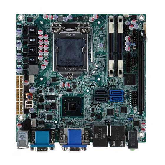
1.1 In tro d u c tio n Figure 1-1: KINO-AQ670 The KINO-AQ670 is a Mini-ITX motherboard. It accepts a LGA1155 Intel® Core™ i7/ i5/ i3/ Celeron® processor and supports two 204-pin 1066/1333 MHz dual-channel DDR3 SO-DIMM modules up to 16 GB. -
Page 17: Connectors
KINO-AQ670 1.2 Co n n e c to rs The connectors on the KINO-AQ670 are shown in the figure below. Figure 1-2: Connectors P a g e 3... -
Page 18: Dimensions
KINO-AQ670 1.3 Dim e n s io n s The dimensions of the board are listed below: Length: 170 mm Width: 170 mm Figure 1-3: KINO-AQ670 Dimensions (mm) P a g e 4... -
Page 19: Data Flow
KINO-AQ670 1.4 Da ta Flow Figure 1-4 shows the data flow between the system chipset, the CPU and other components installed on the motherboard. Figure 1-4: Data Flow Diagram P a g e 5... -
Page 20: Technical Specifications
KINO-AQ670 1.5 Te c h n ic a l Sp e c ific a tio n s KINO-AQ670 technical specifications are listed below. S p e c ific a tio n KINO-AQ670 Fo rm Fa c to r Mini-ITX S o c ke t... -
Page 21: Table 1-1: Technical Specifications
KINO-AQ670 S p e c ific a tio n KINO-AQ670 One 20-pin header One 4-pin CPU fan connector Fa n One 4-pin PCH fan connector Two external RS-232 via DB-9 male connectors S e ria l P o rts Two external USB 2.0 ports on rear IO US B P o rts Two external USB 3.0 ports on rear IO by Fresco FL009... -
Page 22: Unpacking
KINO-AQ670 Chapter Un p a c kin g P a g e 8... -
Page 23: Anti Static Precautions
Only handle the edges of the PCB: Don't touch the surface of the motherboard. Hold the motherboard by the edges when handling. 2.2 Un pa c kin g P re c a u tio n s When the KINO-AQ670 is unpacked, please do the following: Follow the antistatic guidelines above. -
Page 24: Packing List
If any of the components listed in the checklist below are missing, do not proceed with the installation. Contact the IEI reseller or vendor the KINO-AQ670 was purchased from or contact an IEI sales representative directly by sending an email to sales@iei.com.tw. -
Page 25: Optional Items
KINO-AQ670 Quick Installation Guide 2.4 Op tio n a l Ite m s The following are optional components which may be separately purchased: Ite m a n d P a rt Nu m b e r Im a g e... -
Page 26: Connectors
KINO-AQ670 Chapter Co n n e c to rs P a g e 12... -
Page 27: Peripheral Interface Connectors
3.1 P e rip h e ra l In te rfa c e Co n n e c to rs This chapter details all the jumpers and connectors. 3.1.1 KINO-AQ670 La yo u t The figures below show all the connectors and jumpers. -
Page 28: Peripheral Interface Connectors
KINO-AQ670 3.1.2 P e rip h e ra l In te rfa c e Co n n e c to rs The table below lists all the connectors on the board. Co n n e c to r Typ e... -
Page 29: Internal Peripheral Connectors
3.2 In te rn a l P e rip h e ra l Co n n e c to rs The section describes all of the connectors on the KINO-AQ670. 3.2.1 ATX P owe r Co n n e c tor... -
Page 30: Battery Connector
KINO-AQ670 Figure 3-2: ATX Power Connector Location PIN NO. DESCRIPTION PIN NO. DESCRIPTION +3.3 V +3.3 V +5 V +5 V PWRGD_PS 5VSB +12 V +12 V +3.3 V +3.3 V -12 V IO_PSON# +5 V +5 V +5 V Table 3-3: ATX Power Connector Pinouts 3.2.2 Ba tte ry Co n n e c to r... -
Page 31: Cpu Power Connector
KINO-AQ670 CN P in o u ts : See Table 3-4 The battery connector is connected to the system battery. The battery provides power to the system clock to retain the time when power is turned off. Figure 3-3: Battery Connector Location PIN NO. -
Page 32: Ddr3 So-Dimm Slots
KINO-AQ670 Figure 3-4: CPU Power Connector Location PIN NO. DESCRIPTION PIN NO. DESCRIPTION VREG_12V VREG_12V Table 3-5: CPU Power Connector Pinouts 3.2.4 DDR3 S O-DIMM S lo ts CN La b e l: CHA_DIMM1, CHB_DIMM1 DDR3 SO-DIMM slot CN Typ e :... -
Page 33: Debug Port Connector
KINO-AQ670 Figure 3-5: DDR3 SO-DIMM Slot Locations 3.2.5 De b u g P o rt Co n n e c to r CN La b e l: DEBUGCN1 CN Typ e : 9-pin header CN Lo c a tio n :... -
Page 34: Digital I/O Connector
KINO-AQ670 Figure 3-6: Debug Port Connector Location PIN NO. DESCRIPTION PIN NO. DESCRIPTION PLT_RST# LPC_DEBUG_CLK LPC_AD3 LPC_AD2 LPC_AD1 LPC_AD0 LPC_FRAME# +3.3V Table 3-6: Debug Port Connector Pinouts 3.2.6 Dig ita l I/O Co n n e c to r CN La b e l:... -
Page 35: Fan Connector (Cpu)
KINO-AQ670 Figure 3-7: Digital I/O Connector Location PIN NO. DESCRIPTION PIN NO. DESCRIPTION DGPO3 DGPO2 DGPO1 DGPO0 DGPI3 DGPI2 DGPI1 DGPI0 Table 3-7: Digital I/O Connector Pinouts 3.2.7 Fa n Co n n e c to r (CP U) CN La b e l:... -
Page 36: Fan Connector (Pch)
KINO-AQ670 Figure 3-8: CPU Fan Connector Locations PIN NO. DESCRIPTION PIN NO. DESCRIPTION +12V FANIO1 FANOUT1 Table 3-8: CPU Fan Connector Pinouts 3.2.8 Fa n Co n n e c to r (P CH) CN La b e l: P CH_FAN... -
Page 37: Front Panel Connector
KINO-AQ670 Figure 3-9: PCH Fan Connector Location PIN NO. DESCRIPTION PIN NO. DESCRIPTION FAN12V FANIO2 Table 3-9: PCH Fan Connector Pinouts 3.2.9 Fro n t P a n e l Co n n e c to r CN La b e l:... -
Page 38: Pcie X16 Slot
KINO-AQ670 Figure 3-10: Front Panel Connector Location PIN NO. DESCRIPTION PIN NO. DESCRIPTION ACPILED BEEP_PWR PWRBTN_SW PC_BEEP IDELED EXTRST# IDELED# Table 3-10: Front Panel Connector Pinouts 3.2.10 P CIe x16 S lo t CN La b e l: P CIEX16... -
Page 39: Sata 3Gb/S Drive Connectors
KINO-AQ670 Figure 3-11: PCIe x16 Slot Location 3.2.11 S ATA 3Gb /s Drive Co n n e c to rs CN La b e l: SATA3, SATA4 7-pin SATA connector CN Typ e : CN Lo c a tio n : See Figure 3-12 The two SATA 3Gb/s drive connectors are each connected to a SATA 3Gb/s drive. -
Page 40: Sata 6Gb/S Drive Connectors
KINO-AQ670 Figure 3-12: SATA 3Gb/s Drive Connector Location 3.2.12 S ATA 6Gb /s Drive Co n n e c to rs CN La b e l: SATA1, SATA2 CN Typ e : 7-pin SATA connector CN Lo c a tio n : See Figure 3-13 The two SATA 6Gb/s drive connectors are each connected to a SATA 6Gb/s drive. -
Page 41: Smbus Connector
KINO-AQ670 Figure 3-13: SATA 6Gb/s Drive Connector Locations 3.2.13 S MBUS Co n n e c to r CN La b e l: S MBUS _1 4-pin wafer CN Typ e : See Figure 3-14 CN Lo c a tio n :... -
Page 42: Spi Connector
KINO-AQ670 Figure 3-14: SMBus Connector Location PIN NO. DESCRIPTION PIN NO. DESCRIPTION +5V_DUAL SMBCLK_RESUME SMBDATA_RESUME Table 3-11: SMBus Connector Pinouts 3.2.14 S P I Co n n e c to r CN La b e l: S P I 8-pin connector... -
Page 43: Tpm Connector
KINO-AQ670 Figure 3-15: SPI Connector Location PIN NO. DESCRIPTION PIN NO. DESCRIPTION +SPI_VCC SPI_CS0#_CN_P SPI_CLK0_CN_P SPI_SO0_CN_P SPI_SI0_CN_P Table 3-12: SPI Connector Pinouts 3.2.15 TP M Co n n e c to r CN La b e l: CN Typ e :... -
Page 44: Usb Connectors
KINO-AQ670 Figure 3-16: TPM Connector Location PIN NO. DESCRIPTION PIN NO. DESCRIPTION TPMPCLK LPC_FRAME# BUF_PCIRST# LPC_AD3 LPC_AD2 +3.3V LPC_AD1 LPC_AD0 SMBCLK_RESUME SMBDATA_RESUME +3V_DUAL SERIRQ +3.3V LPCPD_N LDRQ0# Table 3-13: TPM Connector Pinouts 3.2.16 US B Co n n e c to rs... -
Page 45: External Peripheral Interface Connector Panel
3.3 Exte rn a l P e rip h e ra l In te rfa c e Co n n e c to r P a n e l Figure 3-18 shows the KINO-AQ670 external peripheral interface connector (EPIC) panel. -
Page 46: Audio Connector
KINO-AQ670 1 x VGA connector Figure 3-18: KINO-AQ670 External Peripheral Interface Connector 3.3.1 Au d io Co n n e c to r CN La b e l: AUDIO_JACK CN Typ e : Audio jack CN Lo c a tio n : See Figure 3-18 The audio jacks connect to external audio devices. -
Page 47: Ethernet And Usb Connectors
KINO-AQ670 3.3.2 Eth e rn e t a n d US B Con n e c to rs CN La b e l: LAN1_USB, LAN2_USB CN Typ e : RJ-45 , USB 2.0 and USB 3.0 ports CN Lo c a tio n :... -
Page 48: Keyboard/Mouse Connector
KINO-AQ670 The USB 3.0 ports are for attaching USB 3.0 peripheral devices to the system. To be able to use the USB 3.0 ports, please make sure the USB 3.0 function is enabled in BIOS (see Section 5.3.6). The pinouts of LAN2 and USB 3.0 connectors are shown below. -
Page 49: Serial Port Connectors
KINO-AQ670 KBDATA +5V_KBMS KBCLK MSDATA +5V_KBMS MSCLK Table 3-17: PS/2 Connector Pinouts 3.3.4 RS -232 S e ria l P o rt Co n n e c to rs CN Label: COM1_2 CN Type: DB-9 Male CN Location: See Figure 3-18... -
Page 50: Vga And Dvi Connector
KINO-AQ670 PIN NO. DESCRIPTION PIN NO. DESCRIPTION NDSR2# NRTS2# NCTS2# NRI2# Table 3-18: RS-232 Serial Port Connector Pinouts 3.3.5 VGA a n d DVI Co n n e c to r CN La b e l: DVI+CRT 15-pin female (VGA) , 24-pin female (DVI) -
Page 51: Table 3-20: Dvi Connector Pinouts
KINO-AQ670 PIN NO. DESCRIPTION PIN NO. DESCRIPTION DVI_TMDS_C_DATA2# DVI_TMDS_C_DATA2 DVI_DDC_SCLK DVI_DDC_SDATA DVI_TMDS_C_DATA1# DVI_TMDS_C_DATA1 +5V_DVI DVI_HPD DVI_TMDS_C_DATA0# DVI_TMDS_C_DATA0 DVI_TMDS_C_CLK DVI_TMDS_C_CLK# Table 3-20: DVI Connector Pinouts P a g e 37... -
Page 52: Installation
KINO-AQ670 Chapter In s ta lla tio n P a g e 38... -
Page 53: Anti - Static Precautions
Electrostatic discharge (ESD) can cause serious damage to electronic components, including the KINO-AQ670. Dry climates are especially susceptible to ESD. It is therefore critical that whenever the KINO-AQ670 or any other electrical component is handled, the following anti-static precautions are strictly adhered to. -
Page 54: Installation Considerations
KINO-AQ670 is installed. All installation notices pertaining to the installation of the KINO-AQ670 should be strictly adhered to. Failing to adhere to these precautions may lead to severe damage of the KINO-AQ670 and injury to the person installing the motherboard. WARNING:... -
Page 55: Basic Installation
The CPU, CPU cooling kit and DIMM are the most critical components of the KINO-AQ670. If one of these component is not installed the KINO-AQ670 cannot run. 4.3.1 S o c ke t LGA1155 CP U In s ta lla tio n WARNING: CPUs are expensive and sensitive components. -
Page 56: Figure 4-1: Disengage The Cpu Socket Load Lever
KINO-AQ670 To install the CPU, follow the steps below. Disengage the load lever by pressing the lever down and slightly outwards to S te p 1: clear the retention tab. Fully open the lever. See Figure 4-1. Figure 4-1: Disengage the CPU Socket Load Lever Open the socket and remove the protective cover. -
Page 57: Figure 4-3: Insert The Socket Lga1155 Cpu
KINO-AQ670 S te p 4: Orientate the CPU properly. The contact array should be facing the CPU socket. Correctly position the CPU. Match the Pin 1 mark with the CPU edge on the S te p 5: CPU socket. Align the CPU pins. Locate pin 1 and the two orientation notches on the CPU. -
Page 58: Cooling Kit Installation
KINO-AQ670 Figure 4-4: Close the Socket LGA1155 Connect the 12 V power to the board. Connect the 12 V power from the power S te p 9: supply to the board. 4.3.2 Co o lin g Kit In s ta lla tio n WARNING: DO NOT attempt to install a push-pin cooling fan. -
Page 59: Figure 4-6: Cooling Kit Support Bracket
KINO-AQ670 WARNING: Do not wipe off (accidentally or otherwise) the pre-sprayed layer of thermal paste on the bottom of the heat sink. The thermal paste between the CPU and the heat sink is important for optimum heat dissipation. To install the cooling kit, follow the instructions below. -
Page 60: Dimm Installation
Connect the fan cable. Connect the cooling kit fan cable to the fan connector S te p 5: on the KINO-AQ670. Carefully route the cable and avoid heat generating chips and fan blades. 4.3.3 DIMM In s ta lla tio n To install a DIMM, please follow the steps below and refer to Figure 4-7. -
Page 61: Jumper Settings
OPEN a jumper means removing the Figure 4-8: Jumper Locations plastic clip from a jumper. Before the KINO-AQ670 is installed in the system, the jumpers must be set in accordance with the desired configuration. The jumpers on the KINO-AQ670 are listed in Table 4-1. Description... -
Page 62: Clear Cmos Jumper
J u m p e r Lo c a tio n : If the KINO-AQ670 fails to boot due to improper BIOS settings, the clear CMOS jumper clears the CMOS data and resets the system BIOS information. To do this, use the jumper cap to close pins 2 and 3 for a few seconds then reinstall the jumper clip back to pins 1 and 2. -
Page 63: Wol Mode Select Jumper
KINO-AQ670 If the “CMOS Settings Wrong” message is displayed during the boot up process, the fault may be corrected by pressing the F1 to enter the CMOS Setup menu. Do one of the following: Enter the correct CMOS setting ... -
Page 64: Internal Peripheral Device Connections
KINO-AQ670 J u m p e r Typ e : 3-pin header J u m p e r S e ttin g s : See Table 4-4 J u m p e r Lo c a tio n : See Figure 4-11 The Wake-on LAN (WOL) mode select jumper allows the user to enable or disable the WOL function. -
Page 65: Sata Drive Connection
KINO-AQ670 4.5.1 S ATA Drive Co n n e c tio n The KINO-AQ670 is shipped with two SATA drive cables and one SATA drive power cable. To connect the SATA drives to the connectors, please follow the steps below. -
Page 66: External Peripheral Interface Connection
Serial port devices USB devices VGA monitor To install these devices, connect the corresponding cable connector from the actual device to the corresponding KINO-AQ670 external peripheral interface connector making sure the pins are properly aligned. P a g e 52... -
Page 67: Audio Connection
4.6.2 DVI Dis p la y De vic e Co n n e c tio n The KINO-AQ670 has a single female DVI connector on the external peripheral interface panel. The DVI connector is connected to a digital display device. To connect a digital display device to the KINO-AQ670, please follow the instructions below. -
Page 68: Lan Connection
S te p 3: male connector, insert the male connector from the digital display device into the female connector on the KINO-AQ670. See Figure 4-15. Figure 4-15: DVI Connector Secure the connector. Secure the DVI connector from the digital display device... -
Page 69: Ps/2 Keyboard And Mouse Connection
4.6.4 P S /2 Ke yb o a rd a n d Mo u s e Co n n e c tio n The KINO-AQ670 has a dual PS/2 connector on the external peripheral interface panel. The dual PS/2 connector is used to connect to a keyboard and mouse to the system. -
Page 70: Serial Device Connection
4.6.5 S e ria l De vic e Co n n e c tio n The KINO-AQ670 has a single female DB-9 connector on the external peripheral interface panel for a serial device. Follow the steps below to connect a serial device to the KINO-AQ670. -
Page 71: Usb Connection
KINO-AQ670 Figure 4-18: Serial Device Connector Secure the connector. Secure the serial device connector to the external S te p 3: interface by tightening the two retention screws on either side of the connector 4.6.6 US B Co n n e c tio n The external USB Series "A"... -
Page 72: Vga Monitor Connection
4.6.7 VGA Mo n ito r Co n n e c tio n The KINO-AQ670 has a single female DB-15 connector on the external peripheral interface panel. The DB-15 connector is connected to a CRT or VGA monitor. To connect a monitor to the KINO-AQ670, please follow the instructions below. -
Page 73: Intel ® Amt Setup Procedure
4.7 In te l AMT S e tu p P ro c e d u re The KINO-AQ670 is featured with the Intel® Active Management Technology (AMT). To enable the Intel® AMT function, follow the steps below. S te p 1: Make sure the CHA_DIMM1 socket is installed with one DDR3 DIMM. - Page 74 KINO-AQ670 process. Enter the Intel® current ME password as it requires (the Intel® default password is admin). NOTE: To change the password, enter a new password following the strong password rule (containing at least one upper case letter, one lower case letter, one digit and one special character, and be at least eight characters).
-
Page 75: Bios Screens
KINO-AQ670 Chapter BIOS S c re e n s P a g e 61... -
Page 76: Introduction
KINO-AQ670 5.1 In tro d u c tio n The BIOS is programmed onto the BIOS chip. The BIOS setup program allows changes to certain system settings. This chapter outlines the options that can be changed. 5.1.1 Sta rtin g S e tu p The AMI BIOS is activated when the computer is turned on. -
Page 77: Getting Help
KINO-AQ670 Ke y Fu n c tio n F4 key Save changes and Exit BIOS Esc key Main Menu – Quit and not save changes into CMOS Status Page Setup Menu and Option Page Setup Menu -- Exit current page and return to Main Menu Table 5-1: BIOS Navigation Keys 5.1.3 Ge ttin g He lp... -
Page 78: Main
KINO-AQ670 5.2 Ma in The Main BIOS menu (BIOS Menu 1) appears when the BIOS Setup program is entered. The Main menu gives an overview of the basic system information. Aptio Setup Utility – Copyright (C) 2011 American Megatrends, Inc. -
Page 79: Advanced
KINO-AQ670 The System Overview field also has two user configurable fields: S ys te m Da te [xx/xx/xx] Use the System Date option to set the system date. Manually enter the day, month and year. S ys te m Tim e [xx:xx:xx] Use the System Time option to set the system time. -
Page 80: Acpi Configuration
KINO-AQ670 Aptio Setup Utility – Copyright (C) 2011 American Megatrends, Inc. Main Advanced Chipset Boot Security Save & Exit > ACPI Settings System ACPI Parameters > Trusted Computing > CPU Configuration > SATA Configuration > Intel TXT(LT) Configuration ---------------------- : Select Screen >... -
Page 81: Trusted Computing
KINO-AQ670 ACP I S le e p Sta te [S 1 (CP U Sto p Clo c k)] Use the ACPI Sleep State option to specify the sleep state the system enters when it is not being used. ... -
Page 82: Cpu Configuration
KINO-AQ670 TPM S u p p o rt [Dis a b le ] Use the TPM Support option to configure support for the TPM. TPM support is disabled. Disable EFAULT Enable TPM support is enabled. 5.3.3 CP U Co n fig u ra tio n Use the CPU Configuration menu (BIOS Menu 5) to enter the CPU Information submenu or enable Intel Virtualization Technology. -
Page 83: Cpu Information
KINO-AQ670 5.3.3.1 CP U In fo rm a tio n Use the CPU Information submenu (BIOS Menu 6) to view detailed CPU specifications and configure the CPU. Aptio Setup Utility – Copyright (C) 2011 American Megatrends, Inc. Advanced CPU Information Intel(R) Pentium(R) CPU G620T @ 2.20GHz... -
Page 84: Sata Configuration
KINO-AQ670 L2 Cache: Lists the amount of storage space on the L2 cache. L3 Cache: Lists the amount of storage space on the L3 cache. 5.3.4 S ATA Co n fig u ra tio n Use the SATA Configuration menu (BIOS Menu 7) to change and/or set the configuration of the SATA devices installed in the system. -
Page 85: Intel Txt(Lt) Configuration
KINO-AQ670 Disables Serial-ATA controller. Disable Enhanced Configures the Serial-ATA controller to be in enhanced mode. In this mode, IDE channels and SATA channels are separated. Some legacy OS do not support this mode. Compatible Configures the Serial-ATA controller to be in compatible EFAULT mode. -
Page 86: Usb Configuration
KINO-AQ670 Aptio Setup Utility – Copyright (C) 2011 American Megatrends, Inc. Advanced Intel Trusted Execution Technology Configuration Intel TXT support only can be enabled/disabled if SMX is enabled. VT and VT-d support must also be enabled prior --------------------- : Select Screen to TXT. - Page 87 KINO-AQ670 US B S u p p o rt [En a b le d ] Use the USB Support option to enable or disable USB support on the system. USB support disabled Disabled Enabled USB support enabled EFAULT ...
- Page 88 KINO-AQ670 EHCI Ha n d -o ff [Dis a b le d ] Use the EHCI Hand-off option to enable or disable EHCI Hand-off on the system. EHCI Hand-off disabled Disabled EFAULT Enabled EHCI Hand-off enabled ...
-
Page 89: Super Io Configuration
KINO-AQ670 5.3.7 S u pe r IO Co n fig u ra tio n Use the Super IO Configuration menu (BIOS Menu 10) to set or change the configurations for the FDD controllers, parallel ports and serial ports. Aptio Setup Utility – Copyright (C) 2011 American Megatrends, Inc. -
Page 90: Serial Port [Enabled]
KINO-AQ670 5.3.7.1.1 S e ria l P o rt 1 Co n fig u ra tio n S e ria l P o rt [En a b le d ] Use the Serial Port option to enable or disable the serial port. -
Page 91: Power Saving Function
KINO-AQ670 Enable the serial port Enabled EFAULT Ch a n g e S e ttin g s [Au to ] Use the Change Settings option to change the serial port IO port address and interrupt address. Auto... -
Page 92: Bios Menu 12: Hardware Health Configuration
KINO-AQ670 Aptio Setup Utility – Copyright (C) 2011 American Megatrends, Inc. Advanced PC Health Status CPU Temperature :+45 C SYS Temperature :+35 C CPU FAN Speed :2209 RPM SYS FAN Speed :N/A VCC3V :+3.392 V V_core :+1.072 V --------------------- : Select Screen :+3.408 V... -
Page 93: Fan 1 Configuration
KINO-AQ670 5.3.8.1 FAN 1 Co n fig u ra tio n Use the FAN 1 Configuration submenu (BIOS Menu 13) to configure fan 1 temperature and speed settings. Aptio Setup Utility – Copyright (C) 2011 American Megatrends, Inc. Advanced PC Health Status... -
Page 94: Fan 2 Configuration
KINO-AQ670 Ta rg e t Te m p . S e n s o r [CP U Te m p e ra tu re ] Use the Target Temp. Sensor option to set the target CPU temperature. Sets the target temperature sensor to the CPU EFAULT temperature. -
Page 95: Bios Menu 14: Fan 2 Configuration
KINO-AQ670 Aptio Setup Utility – Copyright (C) 2011 American Megatrends, Inc. Advanced PC Health Status SYS Smart Fan control [Auto by Duty-Cycle] Target Temp Sensor [CPU Temperature] Temperature Bound 1 Temperature Bound 2 Temperature Bound 3 Temperature Bound 4 Segment 1 Speed (PWM) --------------------- : Select Screen... -
Page 96: Serial Port Console Redirection
KINO-AQ670 Sets the target temperature sensor to the System System Temperature1 Temperature1 setting. System Sets the target temperature sensor to the System Temperature2 setting. Temperature2 Te m p e ra tu re Bo u n d n Use the + or –... -
Page 97: Iei Feature
KINO-AQ670 Co n s o le Re d ire c tio n [Dis a b le d ] Use Console Redirection option to enable or disable the console redirection function. Disabled the console redirection function Disabled EFAULT ... -
Page 98: Chipset
KINO-AQ670 Auto recovery function enabled Enabled 5.4 Ch ips e t Use the Chipset menu (BIOS Menu 17) to access the Northbridge and Southbridge configuration menus WARNING! Setting the wrong values for the Chipset BIOS selections in the Chipset BIOS menu may cause the system to malfunction. -
Page 99: Northbridge Configuration
KINO-AQ670 5.4.1 No rth b rid g e Co n fig u ra tio n Use the Northbridge Chipset Configuration menu (BIOS Menu 18) to configure the Northbridge chipset. Aptio Setup Utility – Copyright (C) 2011 American Megatrends, Inc. Chipset... - Page 100 KINO-AQ670 IGD Me m o ry [64 M] Use the IGD Memory option to specify the amount of system memory that can be used by the internal graphics device. Disable 32 M 32 MB of memory used by internal graphics device ...
-
Page 101: Southbridge Configuration
KINO-AQ670 480 MB of memory used by internal graphics 480 M device 512 M 512 MB of memory used by internal graphics device P CI Exp re s s P o rt [En a b le d ] Use the PCI Express Port option to enable or disable the PCI Express port. -
Page 102: Bios Menu 19: Southbridge Chipset Configuration
KINO-AQ670 Aptio Setup Utility – Copyright (C) 2011 American Megatrends, Inc. Chipset Auto Power Button Status [OFF] Enabled/Disabled All USB controllers USB Controller [Enabled] On-Chip GbE Configuration GbE Controller [Enabled] GbE PXE Boot [Disabled] Wake Event Configuration Restore AC Power Loss... - Page 103 KINO-AQ670 Gb E P XE Bo o t [Dis a b le d ] Use the GbE PXE Boot option to enable or disable the boot option for GbE devices. Disables the GbE PXE Boot option Disabled EFAULT ...
- Page 104 KINO-AQ670 Disables Resume on Ring option Disabled Enabled Enables Resume on Ring option EFAULT Re s u m e o n P S /2 [En a b le d ] Use the Resume on PS/2 option to enable or disable resuming from PS/2 activation.
-
Page 105: Integrated Graphics
KINO-AQ670 The onboard PCIe LAN controller is disabled Disabled Enabled The onboard PCIe LAN controller is enabled EFAULT P CIe LAN P XE Bo o t [Dis a b le d ] Use the PCIe LAN PXE Boot option to enable or disable the boot option for the PCIe LAN PXE. -
Page 106: Bios Menu 20: Integrated Graphics
KINO-AQ670 Aptio Setup Utility – Copyright (C) 2011 American Megatrends, Inc. Advanced Intel IGD SWSCI OpRegion Configuration Select DVMT Mode used by Internal Graphics DVMT Mode Select [DVMT Mode] Device. If Fixed Mode DVMT Memory [Maximum] selected, IGD Memory might need to be changed... -
Page 107: Me Subsystem
KINO-AQ670 IGD - Bo o t Typ e [AUTO] Use the IGD - Boot Type option to select the display device used by the system when it boots. For dual display support, select “Auto.” Configuration options are listed below. -
Page 108: Boot
KINO-AQ670 Enables user to enter MEBx setup Enter MEBx Setup Un c o n fig u re AMT/ME [Dis a b le d ] Use the Unconfigure AMT/ME option to perform AMT/ME unconfigure without password operation. Not perform AMT/ME unconfigure... - Page 109 KINO-AQ670 Allows the Number Lock on the keyboard to be EFAULT enabled automatically when the computer system boots up. This allows the immediate use of the 10-key numeric keypad located on the right side of the keyboard. To confirm this, the Number Lock LED light on the keyboard is lit.
-
Page 110: Security
KINO-AQ670 5.6 S e c u rity Use the Security menu (BIOS Menu 23) to set system and user passwords. Aptio Setup Utility – Copyright (C) 2011 American Megatrends, Inc. Main Advanced Chipset Boot Security Save & Exit Password Description... -
Page 111: Save & Exit
KINO-AQ670 5.7 S a ve & Exit Use the Save & Exit menu (BIOS Menu 24) to load default BIOS values, optimal failsafe values and to save configuration changes. Aptio Setup Utility – Copyright (C) 2011 American Megatrends, Inc. Main... - Page 112 KINO-AQ670 S a ve a s Us e r De fa u lts Use the Save as User Defaults option to save the changes done so far as user defaults. Re s to re Us e r De fa u lts Use the Restore User Defaults option to restore the user defaults to all the setup options.
-
Page 113: Software Drivers
KINO-AQ670 Chapter S o ftwa re Drive rs P a g e 99... -
Page 114: Available Software Drivers
Installation instructions are given below. 6.2 S o ftwa re In s ta lla tio n All the drivers for the KINO-AQ670 are on the CD that came with the system. To install the drivers, please follow the steps below. -
Page 115: Figure 6-1: Introduction Screen
KINO-AQ670 Figure 6-1: Introduction Screen S te p 3: Click KINO-AQ670. A new screen with a list of available drivers appears (Figure 6-2). S te p 4: Figure 6-2: Available Drivers P a g e 101... -
Page 116: Chipset Driver Installation
KINO-AQ670 S te p 5: Install all of the necessary drivers in this menu. 6.3 Ch ips e t Drive r In s ta lla tio n To install the chipset driver, please do the following. S te p 1: Access the driver list. -
Page 117: Figure 6-4: Chipset Driver Welcome Screen
KINO-AQ670 Figure 6-4: Chipset Driver Welcome Screen The license agreement in Figure 6-5 appears. S te p 7: Read the License Agreement. S te p 8: Click Yes to continue. S te p 9: Figure 6-5: Chipset Driver License Agreement S te p 10: The Read Me file in Figure 6-6 appears. -
Page 118: Figure 6-6: Chipset Driver Read Me File
KINO-AQ670 Click Next to continue. S te p 11: Figure 6-6: Chipset Driver Read Me File Setup Operations are performed as shown in Figure 6-7. S te p 12: Once the Setup Operations are complete, click Next to continue. S te p 13:... -
Page 119: Graphics Driver Installation
KINO-AQ670 The Finish screen in Figure 6-8 appears. S te p 14: Select “Yes, I want to restart this computer now” and click Finish.S te p 0: S te p 15: Figure 6-8: Chipset Driver Installation Finish Screen 6.4 Gra p h ic s Drive r In s ta lla tio n To install the Graphics driver, please do the following. -
Page 120: Figure 6-9: Graphics Driver Welcome Screen
KINO-AQ670 Figure 6-9: Graphics Driver Welcome Screen The License Agreement in Figure 6-10 appears. S te p 6: S te p 7: Click Yes to accept the agreement and continue. Figure 6-10: Graphics Driver License Agreement Setup Operations are performed as shown in Figure 6-11. -
Page 121: Figure 6-11: Graphics Driver Setup Operations
KINO-AQ670 Once the Setup Operations are complete, click Next to continue. S te p 9: Figure 6-11: Graphics Driver Setup Operations The Finish screen in Figure 6-12 appears. S te p 10: Select “Yes, I want to restart this computer now” and click Finish.S te p 0:... -
Page 122: Lan Driver Installation
KINO-AQ670 6.5 LAN Drive r In s ta lla tio n To install the LAN driver, please do the following. S te p 1: Access the driver list. (See Section 6.2) Click “LAN”. S te p 2: Locate the Autorun file and double click it. -
Page 123: Figure 6-14: Lan Driver Welcome Screen
KINO-AQ670 Figure 6-14: LAN Driver Welcome Screen S te p 7: Click Next to continue. The License Agreement in Figure 6-15 appears. S te p 8: Accept the agreement by selecting “I accept the terms in the license S te p 9: agreement”. -
Page 124: Figure 6-16: Lan Driver Setup Options
KINO-AQ670 The Setup Options screen in Figure 6-16 appears. S te p 11: Select program features to install. S te p 12: Click Next to continue. S te p 13: Figure 6-16: LAN Driver Setup Options S te p 14: The Ready to Install the Program screen in Figure 6-17 appears. -
Page 125: Figure 6-17: Lan Driver Installation
KINO-AQ670 Figure 6-17: LAN Driver Installation S te p 16: The program begins to install. When the driver installation is complete, the screen in Figure 6-18 appears. S te p 17: Click Finish to exit. S te p 18: Figure 6-18: LAN Driver Installation Complete... -
Page 126: Audio Driver Installation
KINO-AQ670 6.6 Au d io Drive r In s ta lla tio n To install the audio driver, please do the following. S te p 1: Access the driver list. (See Section 6.2) Click “Audio” and select the folder which corresponds to the operating system. -
Page 127: Figure 6-20: Audio Driver Welcome Screen
KINO-AQ670 Figure 6-20: Audio Driver Welcome Screen S te p 7: The audio driver installation begins. See Figure 6-21. Figure 6-21: Audio Driver Installation When the installation is complete, the screen in Figure 6-22 appears. S te p 8: Select “Yes, I want to restart my computer now” and click OK. -
Page 128: Usb 3.0 Driver Installation
KINO-AQ670 6.7 US B 3.0 Drive r In s ta lla tio n To install the touch panel software driver, please follow the steps below. S te p 1: Access the driver list. (See Section 6.2) Click “USB 3.0”. S te p 2: Locate the setup file and double click on it. -
Page 129: Figure 6-24: Usb 3.0 Driver License Agreement
KINO-AQ670 Figure 6-24: USB 3.0 Driver License Agreement Browse for an install location or use the one suggested (Figure 6-25). S te p 9: Click N to continue. S te p 10: Figure 6-25: USB 3.0 Driver Choose Install Location The Ready to Install the Program screen in Figure 6-26 appears. -
Page 130: Figure 6-26: Usb 3.0 Driver Installation
KINO-AQ670 Figure 6-26: USB 3.0 Driver Installation S te p 13: The Install screen appears and displays the progress of the installation. When the installation is complete, click Finish to exit setup. (Figure 6-27). S te p 14: Figure 6-27: USB 3.0 Driver Update Complete... -
Page 131: Intel ® Amt Driver And Application
KINO-AQ670 6.8 In te l® AMT Drive r a n d Ap p lic a tio n 6.8.1 In te l® Ma n a ge m e n t En g in e Co m p o n e n ts In s ta lla tio n The package of the Intel®... -
Page 132: Figure 6-28: Intel® Me Driver Welcome Screen
KINO-AQ670 Figure 6-28: Intel® ME Driver Welcome Screen The license agreement in Figure 6-29 appears. S te p 7: Read the License Agreement. S te p 8: Click Yes to continue. S te p 9: Figure 6-29: Intel® ME Driver License Agreement... -
Page 133: Figure 6-30: Intel® Me Driver Read Me File
KINO-AQ670 The Read Me file in Figure 6-30 appears. S te p 10: Click Next to continue. S te p 11: Figure 6-30: Intel® ME Driver Read Me File Setup Operations are performed as shown in Figure 6-31. S te p 12: S te p 13: Once the Setup Operations are complete, click Next to continue. -
Page 134: Figure 6-31: Intel® Me Driver Setup Operations
KINO-AQ670 Figure 6-31: Intel® ME Driver Setup Operations The Finish screen in Figure 6-32 appears. S te p 14: Select “Yes, I want to restart this computer now” and click Finish.S te p 0: S te p 15: Figure 6-32: Intel® ME Driver Installation Finish Screen... -
Page 135: Intel® It Director Application Installation
KINO-AQ670 6.8.2 In te l® IT Dire c to r Ap p lic a tio n In s ta lla tio n Intel® IT Director is an application that helps address key IT security, data protection and network health concerns of small businesses. To install the Intel® IT Director application, please do the following. -
Page 136: Figure 6-33: It Director Welcome Screen
KINO-AQ670 Figure 6-33: IT Director Welcome Screen S te p 7: The license agreement in Figure 6-34 appears. Accept the agreement by selecting “I accept the terms in the license S te p 8: agreement”. S te p 9: Click Next to continue. -
Page 137: Figure 6-35: It Director Installation
KINO-AQ670 Director application. The Ready to Install the Program screen in Figure 6-35 appears. S te p 11: Click Install to proceed with the installation. S te p 12: Figure 6-35: IT Director Installation The program begins to install. S te p 13: S te p 14: When the driver installation is complete, the screen in Figure 6-36 appears. -
Page 138: Figure 6-36: It Director Installation Complete
KINO-AQ670 Figure 6-36: IT Director Installation Complete The Welcome Screen of the IT Director Configuration Tool in Figure 6-37 S te p 16: appears. Figure 6-37: IT Director Configuration Tool Welcome Screen P a g e 124... -
Page 139: Figure 6-38: It Director - Creating Password
KINO-AQ670 NOTE: It is recommended to open the Intel® IT Director Getting Started Guide shown in Figure 6-37 to fully understand the configuration process. Select whether this is the first computer you are creating a password for IT S te p 17: Director. -
Page 140: Figure 6-39: It Director Configuration Complete
KINO-AQ670 Figure 6-39: IT Director Configuration Complete S te p 0: NOTE: If the network connection doesn’t work after installing the Intel® IT Director in a Windows Vista system, please install the network adapter driver. The driver is located at \7-iAMT, iTPM Driver & Utility\AMT Hot Fix\V1.0C0206 of the driver CD. -
Page 141: A Bios Menu Options
KINO-AQ670 Ap p e n d ix BIOS Me n u Op tio n s P a g e 127... - Page 142 KINO-AQ670 BIOS Information .........................64 Memory Information ......................64 System Date [xx/xx/xx] ......................65 System Time [xx:xx:xx] .......................65 ACPI Sleep State [S1 (CPU Stop Clock)] ................67 TPM Support [Disable] ......................68 Intel Virtualization Technology [Disabled] ................68 ...
- Page 143 KINO-AQ670 Console Redirection [Disabled] ..................83 Auto Recovery Function [Disabled] ...................83 Initiate Graphic Adapter [PEG/IGD] ..................85 IGD Memory [64 M] ......................86 PCI Express Port [Enabled] ....................87 VT-d [Disabled] ........................87 USB Controller [Enabled] ....................88 ...
- Page 144 KINO-AQ670 Restore User Defaults ......................98 P a g e 130...
-
Page 145: B One Key Recovery
KINO-AQ670 Ap p e n d ix On e Ke y Re c o ve ry P a g e 131... -
Page 146: One Key Recovery Introduction
KINO-AQ670 B.1 On e Ke y Re c o ve ry In tro d u c tio n The IEI one key recovery is an easy-to-use front end for the Norton Ghost system backup and recovery tool. This tool provides quick and easy shortcuts for creating a backup and reverting to that backup or reverting to the factory default settings. -
Page 147: System Requirement
KINO-AQ670 After completing the five initial setup procedures as described above, users can access the recovery tool by pressing <F3> while booting up the system. The detailed information of each function is described in Section B.5. NOTE: The initial setup procedures for Linux system are described in Section B.3. -
Page 148: Supported Operating System
KINO-AQ670 partitions. Please take the following table as a reference when calculating the size of the partition. OS Image after Ghost Compression Ratio Windows® 7 7 GB 5 GB Windows® XPE 776 MB 560 MB Windows® CE 6.0 36 MB... -
Page 149: Setup Procedure For Windows
KINO-AQ670 Ubuntu 8.10 (Intrepid) Ubuntu 7.10 (Gutsy) Ubuntu 6.10 (Edgy) Debian 5.0 (Lenny) Debian 4.0 (Etch) SuSe 11.2 SuSe 10.3 NOTE: Installing unsupported OS versions may cause the recovery tool to fail. B.2 S e tu p P ro c e d u re fo r Win d ows Prior to using the recovery tool to backup or restore, a few setup procedures are required. -
Page 150: Hardware And Bios Setup
KINO-AQ670 B.2.1 Ha rdwa re a n d BIOS S e tu p Make sure the system is powered off and unplugged. S te p 1: Install a hard drive or SSD in the system. An unformatted and unpartitioned disk S te p 2: is recommended. -
Page 151: Figure B-2: Launching The Recovery Tool
KINO-AQ670 Figure B-2: Launching the Recovery Tool S te p 3: The recovery tool setup menu is shown as below. Figure B-3: Recovery Tool Setup Menu S te p 4: Press <6> then <Enter>. P a g e 137... -
Page 152: Figure B-4: Command Prompt
KINO-AQ670 Figure B-4: Command Prompt S te p 5: The command prompt window appears. Type the following commands (marked in red) to create two partitions. One is for the OS installation; the other is for saving recovery files and images which will be an invisible partition. -
Page 153: Figure B-5: Partition Creation Commands
KINO-AQ670 Figure B-5: Partition Creation Commands P a g e 139... -
Page 154: Install Operating System, Drivers And Applications
KINO-AQ670 NOTE: Use the following commands to check if the partitions were created successfully. S te p 6: Press any key to exit the recovery tool and automatically reboot the system. Please continue to the following procedure: Build the Recovery Partition.S t e p 0 :... -
Page 155: Building The Recovery Partition
KINO-AQ670 B.2.4 Bu ild in g th e Re c o ve ry P a rtitio n Put the recover CD in the optical drive. S te p 1: Start the system. S te p 2: S te p 3: Boot the system from the recovery CD. -
Page 156: Figure B-8: Building The Recovery Partition
KINO-AQ670 S te p 5: The Symantec Ghost window appears and starts configuring the system to build a recovery partition. In this process the partition created for recovery files in Section B.2.2 is hidden and the recovery tool is saved in this partition. -
Page 157: Create Factory Default Image
KINO-AQ670 B.2.5 Cre a te Fa c to ry De fa u lt Im a g e NOTE: Before creating the factory default image, please configure the system to a factory default environment, including driver and application installations. To create a factory default image, please follow the steps below. -
Page 158: Figure B-12: About Symantec Ghost Window
KINO-AQ670 Figure B-12: About Symantec Ghost Window Use mouse to navigate to the option shown below (Figure B-13). S te p 4: Figure B-13: Symantec Ghost Path S te p 5: Select the local source drive (Drive 1) as shown in Figure B-14. Then click OK. -
Page 159: Figure B-14: Select A Local Source Drive
KINO-AQ670 Figure B-14: Select a Local Source Drive S te p 6: Select a source partition (Part 1) from basic drive as shown in Figure B-15. Then click OK. Figure B-15: Select a Source Partition from Basic Drive Select 1.2: [Recovery] NTFS drive and enter a file name called S te p 7: (Figure B-16). -
Page 160: Figure B-16: File Name To Copy Image To
KINO-AQ670 Figure B-16: File Name to Copy Image to When the Compress Image screen in Figure B-17 prompts, click High to make S te p 8: the image file smaller. Figure B-17: Compress Image P a g e 146... -
Page 161: Figure B-18: Image Creation Confirmation
KINO-AQ670 The Proceed with partition image creation window appears, click Yes to S te p 9: continue. Figure B-18: Image Creation Confirmation The Symantec Ghost starts to create the factory default image (Figure B-19). S te p 10: Figure B-19: Image Creation Complete When the image creation completes, a screen prompts as shown in Figure B-20. -
Page 162: Auto Recovery Setup Procedure
KINO-AQ670 S te p 12: The recovery tool main menu window is shown as below. Press any key to reboot the system. S t e p 0 : Figure B-21: Press Any Key to Continue B.3 Au to Re c o ve ry S e tu p P ro c e d u re... -
Page 163: Figure B-22: Auto Recovery Utility
KINO-AQ670 Figure B-22: Auto Recovery Utility Reboot the system from the recovery CD. When prompted, press any key to S te p 3: boot from the recovery CD. It will take a while to launch the recovery tool. Please be patient! -
Page 164: Figure B-25: Building The Auto Recovery Partition
KINO-AQ670 S te p 5: The Symantec Ghost window appears and starts configuring the system to build an auto recovery partition. In this process the partition created for recovery files in Section B.2.2 is hidden and the auto recovery tool is saved in this partition. -
Page 165: Figure B-27: Image Creation Complete
KINO-AQ670 The Symantec Ghost starts to create the factory default image (Figure B-27). S te p 7: Figure B-27: Image Creation Complete S te p 8: After completing the system configuration, press any key in the following window to restart the system. -
Page 166: Setup Procedure For Linux
KINO-AQ670 BIOS SETUP UTILITY Main Advanced PCIPNP Boot Security Chipset Exit iEi Feature Auto Recovery Function [Enabled] Recover from PXE [Disabled] Select Screen ↑ ↓ Select Item Enter Go to SubScreen General Help Save and Exit Exit v02.61 ©Copyright 1985-2006, American Megatrends, Inc. -
Page 167: Figure B-29: Partitions For Linux
KINO-AQ670 Install Linux operating system. Make sure to install GRUB (v0.97 or earlier) S te p 2: MBR type and Ext3 partition type. Leave enough space on the hard drive to create the recover partition later. NOTE: If the Linux OS is not installed with GRUB (v0.97 or earlier) and Ext3, the Symantec Ghost may not function properly. -
Page 168: Figure B-30: Manual Recovery Environment For Linux
KINO-AQ670 DISKPART>create part pri size= DISKPART>assign letter=N DISKPART>exit system32>format N: /fs:ntfs /q /v:Recovery /y system32>exit Build the recovery partition. Press any key to boot from the recovery CD. It will S te p 4: take a while to launch the recovery tool. Please be patient. When the recovery tool setup menu appears, type <3>... -
Page 169: Figure B-31: Access Menu.lst In Linux (Text Mode)
KINO-AQ670 Figure B-31: Access menu.lst in Linux (Text Mode) Modify the menu.lst as shown below. S te p 6: The recovery tool menu appears. (Figure B-32) S te p 7: Figure B-32: Recovery Tool Menu Create a factory default image. Follow... -
Page 170: Recovery Tool Functions
KINO-AQ670 B.5 Re c o ve ry To o l Fu n c tio n s After completing the initial setup procedures as described above, users can access the recovery tool by pressing <F3> while booting up the system. However, if the setup procedure in Section B.3 has been completed and the auto recovery function is enabled,... -
Page 171: Factory Restore
KINO-AQ670 WARNING: All data in the system will be deleted during the system recovery. Please backup the system files before restoring the system (either Factory Restore or Restore Backup). B.5.1 Fa c to ry Re s to re To restore the factory default image, please follow the steps below. -
Page 172: Backup System
KINO-AQ670 Figure B-35: Recovery Complete Window B.5.2 Ba c ku p S ys te m To backup the system, please follow the steps below. Type <2> and press <Enter> in the main menu. S te p 1: The Symantec Ghost window appears and starts to backup the system. A S te p 2: backup image called iei_user.GHO is created in the hidden Recovery partition. -
Page 173: Restore Your Last Backup
KINO-AQ670 Figure B-37: System Backup Complete Window B.5.3 Re s to re Yo u r La s t Ba c ku p To restore the last system backup, please follow the steps below. Type <3> and press <Enter> in the main menu. -
Page 174: Manual
KINO-AQ670 Figure B-39: Restore System Backup Complete Window B.5.4 Ma n u a l To restore the last system backup, please follow the steps below. Type <4> and press <Enter> in the main menu. S te p 4: The Symantec Ghost window appears. Use the Ghost program to backup or S te p 5: recover the system manually. -
Page 175: Restore Systems From A Linux Server Through Lan
KINO-AQ670 B.6 Re s to re S ys te m s fro m a Lin u x S e rve r thro u g h LAN The One Key Recovery allows a client system to automatically restore to a factory default image saved in a Linux system (the server) through LAN connectivity after encountering a Blue Screen of Death (BSoD) or a hang for around 10 minutes. -
Page 176: Configure Dhcp Server Settings
KINO-AQ670 B.6.1 Co n fig u re DHCP S e rve r S e ttin g s Install the DHCP S te p 1: #yum install dhcp (CentOS, commands marked in red) #apt-get install dhcp3-server (Debian, commands marked in blue) Confirm the operating system default settings: dhcpd.conf. -
Page 177: Configure Tftp Settings
KINO-AQ670 filename “pxelinux.0”; B.6.2 Co n fig u re TFTP S e ttin g s S te p 1: Install the tftp, httpd and syslinux. #yum install tftp-server httpd syslinux (CentOS) #apt-get install tftpd-hpa xinetd syslinux (Debian) S te p 2: Enable the TFTP server by editing the “/etc/xinetd.d/tftp”... -
Page 178: Configure One Key Recovery Server Settings
KINO-AQ670 Debian Replace the TFTP settings from “inetd” to “xinetd” and annotate the “inetd” by adding “#”. #vi /etc/inetd.conf Modify: #tftp dgram udp wait root /usr/sbin..(as shown below) #vi /etc/xinetd.d/tftp B.6.3 Co n fig u re On e Ke y Re c o ve ry S e rve r S e ttin g s Copy the Utility/RECOVERYR10.TAR.BZ2 package from the One Key... -
Page 179: Start The Dhcp, Tftp And Http
KINO-AQ670 B.6.4 Sta rt th e DHCP, TFTP a n d HTTP Start the DHCP, TFTP and HTTP. For example: CentOS #service xinetd restart #service httpd restart #service dhcpd restart Debian #/etc/init.d/xinetd reload #/etc/init.d/xinetd restart #/etc/init.d/dhcp3-server restart B.6.5 Cre a te S ha re d Dire c to ry S te p 1: Install the samba. -
Page 180: Setup A Client System For Auto Recovery
KINO-AQ670 Modify: [image] comment = One Key Recovery path = /share/image browseable = yes writable = yes public = yes create mask = 0644 directory mask = 0755 S te p 4: Edit “/etc/samba/smb.conf” for your environment. For example: Modify the hostname... - Page 181 KINO-AQ670 Continue to configure the Boot Option Priorities BIOS option of the client S te p 2: system: Boot Option #1 remain the default setting to boot from the original OS. Boot Option #2 select the boot from LAN option.
- Page 182 KINO-AQ670 NOTE: A firewall or a SELinux is not in use in the whole setup process. If there is a firewall or a SELinux protecting the system, modify the configuration information to accommodate them. P a g e 168...
-
Page 183: Other Information
KINO-AQ670 B.7 Oth e r In fo rm a tio n B.7.1 Us in g AHCI Mo d e o r ALi M5283 / VIA VT6421A Co n tro lle r When the system uses AHCI mode or some specific SATA controllers such as ALi M5283 or VIA VT6421A, the SATA RAID/AHCI driver must be installed before using one key recovery. - Page 184 KINO-AQ670 When the following window appears, press <S> to select “Specify Additional S te p 5: Device”. In the following window, select a SATA controller mode used in the system. Then S te p 6: press <Enter>. The user can now start using the SATA HDD.
-
Page 185: System Memory Requirement
KINO-AQ670 S te p 7: After pressing <Enter>, the system will get into the recovery tool setup menu. Continue to follow the setup procedure from Step 4 in Section B.2.2 Create Partitions to finish the whole setup process. S t e p 0 : B.7.2 S ys te m Me m o ry Re q u ire m e n t... -
Page 186: C Terminology
KINO-AQ670 Ap p e n d ix Te rm in o lo g y P a g e 172... - Page 187 KINO-AQ670 AC ’97 Audio Codec 97 (AC’97) refers to a codec standard developed by Intel® in 1997. ACPI Advanced Configuration and Power Interface (ACPI) is an OS-directed configuration, power management, and thermal management interface. AHCI Advanced Host Controller Interface (AHCI) is a SATA Host controller register-level interface.
- Page 188 KINO-AQ670 computer is usually a male DE-9 connector. The Digital-to-Analog Converter (DAC) converts digital signals to analog signals. Double Data Rate refers to a data bus transferring data on both the rising and falling edges of the clock signal. Direct Memory Access (DMA) enables some peripheral devices to bypass the system processor and communicate directly with the system memory.
- Page 189 KINO-AQ670 PCIe PCI Express (PCIe) is a communications bus that uses dual data lines for full-duplex (two-way) serial (point-to-point) communications between the SBC components and/or expansion cards and the SBC chipsets. Each line has a 2.5 Gbps data transmission rate and a 250 MBps sustained data transfer rate.
- Page 190 KINO-AQ670 USB 2.0 supports 480Mbps data transfer rates. The Video Graphics Array (VGA) is a graphics display system developed by IBM. P a g e 176...
-
Page 191: D Watchdog Timer
KINO-AQ670 Ap p e n d ix Wa tc h d o g Tim e r P a g e 177... - Page 192 KINO-AQ670 NOTE: The following discussion applies to DOS environment. IEI support is contacted or the IEI website visited for specific drivers for more sophisticated operating systems, e.g., Windows and Linux. The Watchdog Timer is provided to ensure that standalone systems can always recover from catastrophic conditions that cause the CPU to crash.
- Page 193 KINO-AQ670 NOTE: When exiting a program it is necessary to disable the Watchdog Timer, otherwise the system resets. Example program: ; INITIAL TIMER PERIOD COUNTER W_LOOP: AX, 6F02H ;setting the time-out value BL, 30H ;time-out value is 48 seconds ; ADD THE APPLICATION PROGRAM HERE EXIT_AP, 1 ;is the application over?
-
Page 194: E Hazardous Materials Disclosure
KINO-AQ670 Ap p e n d ix Ha za rd o u s Ma te ria ls Dis c lo s u re P a g e 180... -
Page 195: Ipb Products Certified As Ercury
KINO-AQ670 E.1 Ha za rd o u s Ma te ria l Dis c lo s ure Ta b le fo r IP B P ro d u c ts Ce rtifie d a s Ro HS Co m p lia n t Un d e r 2002/95/EC With o u t... - Page 196 KINO-AQ670 Part Name Toxic or Hazardous Substances and Elements Lead Mercury Cadmium Hexavalent Polybrominated Polybrominated (Pb) (Hg) (Cd) Chromium Biphenyls Diphenyl Ethers (CR(VI)) (PBB) (PBDE) Housing Display Printed Circuit Board Metal Fasteners Cable Assembly Fan Assembly Power Supply Assemblies Battery...
- Page 197 KINO-AQ670 此附件旨在确保本产品符合中国 RoHS 标准。以下表格标示此产品中某有毒物质的含量符 合中国 RoHS 标准规定的限量要求。 本产品上会附有”环境友好使用期限”的标签,此期限是估算这些物质”不会有泄漏或突变”的 年限。本 产品可能包含有较短的环境友好使用期限的可替换元件,像是电池或灯管,这些元 件将会单独标示出来。 部件名称 有毒有害物质或元素 铅 汞 镉 六价铬 多溴联苯 多溴二苯醚 (Pb) (Hg) (Cd) (CR(VI)) (PBB) (PBDE) 壳体 显示 印刷电路板 金属螺帽 电缆组装 风扇组装 电力供应组装 电池 O: 表示该有毒有害物质在该部件所有物质材料中的含量均在 SJ/T11363-2006 标准规定的限量要求以下。 X: 表示该有毒有害物质至少在该部件的某一均质材料中的含量超出 SJ/T11363-2006 标准规定的限量要求。...
Need help?
Do you have a question about the KINO-AQ670 and is the answer not in the manual?
Questions and answers