Sign In
Upload
Manuals
Brands
IEI Technology Manuals
Motherboard
KINO-AQ670
IEI Technology KINO-AQ670 Motherboard Manuals
Manuals and User Guides for IEI Technology KINO-AQ670 Motherboard. We have
1
IEI Technology KINO-AQ670 Motherboard manual available for free PDF download: User Manual
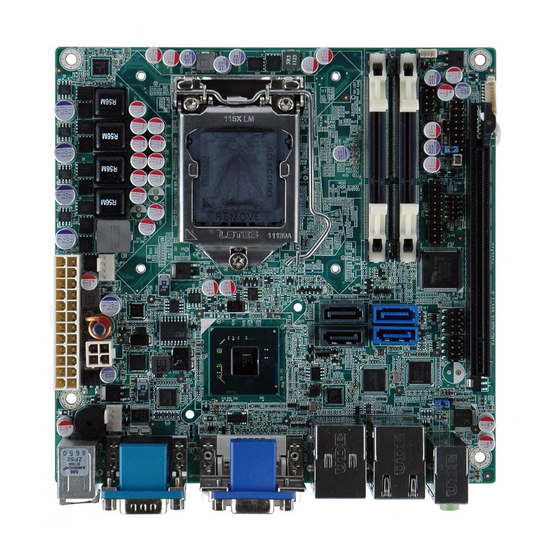
IEI Technology KINO-AQ670 User Manual (197 pages)
Mini-ITX SBC Supports LGA1155 Intel Core i7/ i5/ i3 CPU, DDR3, VGA/DVI-D, 2 COM, Intel GbE, SATA 6Gb/s , USB 3.0, HD Audio and RoHS
Brand:
IEI Technology
| Category:
Motherboard
| Size: 9.15 MB
Table of Contents
Table of Contents
4
Introduction
15
Figure 1-1: KINO-AQ670
16
Introduction
16
Connectors
17
Figure 1-2: Connectors
17
Dimensions
18
Figure 1-3: KINO-AQ670 Dimensions (MM)
18
Data Flow
19
Figure 1-4: Data Flow Diagram
19
Technical Specifications
20
Table 1-1: Technical Specifications
21
2 Unpacking
22
Anti Static Precautions
23
Unpacking Precautions
23
Packing List
24
Optional Items
25
Connectors
26
Figure 3-1: Connector and Jumper Locations
27
KINO-AQ670 Layout
27
Peripheral Interface Connectors
27
External Interface Panel Connectors
28
Peripheral Interface Connectors
28
Table 3-1: Peripheral Interface Connectors
28
ATX Power Connector
29
Internal Peripheral Connectors
29
Table 3-2: Rear Panel Connectors
29
Battery Connector
30
Figure 3-2: ATX Power Connector Location
30
Table 3-3: ATX Power Connector Pinouts
30
CPU Power Connector
31
Figure 3-3: Battery Connector Location
31
Table 3-4: Battery Connector Pinouts
31
DDR3 SO-DIMM Slots
32
Figure 3-4: CPU Power Connector Location
32
Table 3-5: CPU Power Connector Pinouts
32
Debug Port Connector
33
Figure 3-5: DDR3 SO-DIMM Slot Locations
33
Digital I/O Connector
34
Figure 3-6: Debug Port Connector Location
34
Table 3-6: Debug Port Connector Pinouts
34
Fan Connector (CPU)
35
Figure 3-7: Digital I/O Connector Location
35
Table 3-7: Digital I/O Connector Pinouts
35
Fan Connector (PCH)
36
Figure 3-8: CPU Fan Connector Locations
36
Table 3-8: CPU Fan Connector Pinouts
36
Figure 3-9: PCH Fan Connector Location
37
Front Panel Connector
37
Table 3-9: PCH Fan Connector Pinouts
37
Figure 3-10: Front Panel Connector Location
38
Pcie X16 Slot
38
Table 3-10: Front Panel Connector Pinouts
38
Figure 3-11: Pcie X16 Slot Location
39
SATA 3Gb/S Drive Connectors
39
Figure 3-12: SATA 3Gb/S Drive Connector Location
40
SATA 6Gb/S Drive Connectors
40
Figure 3-13: SATA 6Gb/S Drive Connector Locations
41
SMBUS Connector
41
Figure 3-14: Smbus Connector Location
42
SPI Connector
42
Table 3-11: Smbus Connector Pinouts
42
Figure 3-15: SPI Connector Location
43
Table 3-12: SPI Connector Pinouts
43
TPM Connector
43
Figure 3-16: TPM Connector Location
44
Table 3-13: TPM Connector Pinouts
44
USB Connectors
44
External Peripheral Interface Connector Panel
45
Figure 3-17: USB Connector Locations
45
Table 3-14: USB Connector Pinouts
45
Audio Connector
46
Figure 3-18: KINO-AQ670 External Peripheral Interface Connector
46
Figure 3-19: Audio Connector
46
Ethernet and USB Connectors
47
Figure 3-20: LAN Connector
47
Table 3-15: LAN1_USB Connector Pinouts
47
Keyboard/Mouse Connector
48
Table 3-16: LAN2_USB Connector Pinouts
48
Figure 3-21: RS-232 Serial Port Connector
49
Serial Port Connectors
49
Table 3-17: PS/2 Connector Pinouts
49
Figure 3-22: VGA Connector
50
Table 3-18: RS-232 Serial Port Connector Pinouts
50
Table 3-19: VGA Connector Pinouts
50
VGA and DVI Connector
50
Table 3-20: DVI Connector Pinouts
51
4 Installation
52
Anti - Static Precautions
53
Installation Considerations
54
Basic Installation
55
Socket LGA1155 CPU Installation
55
Figure 4-1: Disengage the CPU Socket Load Lever
56
Figure 4-2: Remove Protective Cover
56
Figure 4-3: Insert the Socket LGA1155 CPU
57
Cooling Kit Installation
58
Figure 4-4: Close the Socket LGA1155
58
Figure 4-5: Cooling Kits (CF-1156A-RS, CF-1156B-RS)
58
Figure 4-6: Cooling Kit Support Bracket
59
DIMM Installation
60
Figure 4-7: DIMM Installation
60
Jumper Settings
61
AT/ATX Mode Select Jumper
61
Figure 4-8: Jumper Locations
61
Table 4-1: Jumpers
61
Clear CMOS Jumper
62
Figure 4-9: AT/ATX Mode Select Jumper Location
62
Table 4-2: AT/ATX Mode Select Jumper Settings
62
Figure 4-10: Clear CMOS Jumper Location
63
Table 4-3: Clear CMOS Jumper Settings
63
WOL Mode Select Jumper
63
Figure 4-11: WOL Mode Select Jumper Location
64
Internal Peripheral Device Connections
64
Table 4-4: WOL Mode Select Jumper Settings
64
Figure 4-12: SATA Drive Cable Connection
65
SATA Drive Connection
65
External Peripheral Interface Connection
66
Figure 4-13: SATA Power Drive Connection
66
Audio Connection
67
DVI Display Device Connection
67
Figure 4-13: Audio Connector
67
Figure 4-15: DVI Connector
68
LAN Connection
68
Figure 4-16: LAN Connection
69
PS/2 Keyboard and Mouse Connection
69
Figure 4-17: PS/2 Keyboard/Mouse Connector
70
Serial Device Connection
70
Figure 4-18: Serial Device Connector
71
USB Connection
71
Figure 4-19: USB Connector
72
VGA Monitor Connection
72
Intel ® Amt Setup Procedure
73
Figure 4-20: VGA Connector
73
5 Bios Screens
75
Introduction
76
Starting Setup
76
Using Setup
76
Getting Help
77
Unable to Reboot after Configuration Changes
77
BIOS Menu Bar
77
Table 5-1: BIOS Navigation Keys
77
BIOS Information
78
Main
78
Memory Information
78
System Date [XX/XX/XX]
78
System Time [XX:XX:XX]
78
Advanced
79
ACPI Configuration
80
BIOS Menu 2: Advanced
80
BIOS Menu 3: ACPI Configuration
80
ACPI Sleep State [S1 (CPU Stop Clock)]
80
Trusted Computing
81
BIOS Menu 4: TPM Configuration
81
TPM Support [Disable]
81
CPU Configuration
82
BIOS Menu 5: CPU Configuration
82
Intel Virtualization Technology [Disabled]
82
CPU Information
83
BIOS Menu 6: CPU Configuration
83
SATA Configuration
84
BIOS Menu 7: IDE Configuration
84
SATA Mode [IDE Mode]
84
Serial-ATA Controller 0 [Compatible]
84
Serial-ATA Controller 1 [Enhanced]
84
Intel TXT(LT) Configuration
85
USB Configuration
86
BIOS Menu 8: Intel TXT(LT) Configuration
86
BIOS Menu 9: USB Configuration
86
EHCI Hand-Off [Disabled]
86
Legacy USB Support [Enabled]
86
USB Devices
86
USB Support [Enabled]
86
USB Transfer Time-Out [20 Sec]
86
USB3.0 Support [Enabled]
86
XHCI Hand-Off [Enabled]
86
Serial Port N Configuration
89
Super IO Configuration
89
BIOS Menu 10: Super IO Configuration
89
BIOS Menu 11: Serial Port N Configuration Menu
89
Change Settings [Auto]
89
Serial Port [Enabled]
89
Serial Port [Enabled]
90
H/W Monitor
91
Power Saving Function
91
BIOS Menu 12: Hardware Health Configuration
92
PC Health Status
92
FAN 1 Configuration
93
BIOS Menu 13: FAN 1 Configuration
93
CPU Smart Fan Control [Auto by RPM]
93
Full Speed Count
93
Segment N Speed (%)
93
Temperature Bound N
93
FAN 2 Configuration
94
BIOS Menu 14: FAN 2 Configuration
95
Serial Port Console Redirection
96
BIOS Menu 15: Serial Port Console Redirection Menu
96
Console Redirection [Disabled]
96
IEI Feature
97
BIOS Menu 16: IEI Feature
97
Auto Recovery Function [Disabled]
97
Chipset
98
BIOS Menu 17: Chipset
98
Northbridge Configuration
99
BIOS Menu 18: Northbridge Chipset Configuration
99
IGD Memory [64M]
99
Initiate Graphic Adapter [PEG/IGD]
99
PCI Express Port [Enabled]
99
VT-D [Disabled]
99
Southbridge Configuration
101
BIOS Menu 19: Southbridge Chipset Configuration
102
Azalia HD Audio [Enabled]
102
Azalia Internal HDMI Codec [Enabled]
102
Gbe Controller [Enabled]
102
Gbe PXE Boot [Disabled]
102
Restore AC Power Loss [Power Off]
102
Resume on PCIE Wake [Enabled]
102
Resume on Pme/Gbe [Enabled]
102
Resume on Ring [Enabled]
102
USB Controller [Enabled]
102
Integrated Graphics
105
Pcie USB3.0 Controller [Enabled]
105
Pcie X8 Slot (Pcie X1) [Enabled]
105
BIOS Menu 20: Integrated Graphics
106
DVMT Memory [Maximum]
106
DVMT Mode Select [DVMT Mode]
106
IGD - Boot Type [AUTO]
106
ME Subsystem
107
BIOS Menu 21: ME Subsystem
107
Mebx Mode [Normal]
107
Unconfigure AMT/ME [Disabled]
107
Boot
108
BIOS Menu 22: Boot
108
Bootup Numlock State [On]
108
Option ROM Messages [Force BIOS]
108
Security
110
BIOS Menu 23: Security
110
Administrator Password
110
User Password
110
Save & Exit
111
BIOS Menu 24:Exit
111
Discard Changes and Reset
111
Restore Defaults
111
Save as User Defaults
111
Save Changes and Reset
111
6 Software Drivers
113
Available Software Drivers
114
Software Installation
114
Figure 6-1: Introduction Screen
115
Figure 6-2: Available Drivers
115
Chipset Driver Installation
116
Figure 6-3: Chipset Driver Screen
116
Figure 6-4: Chipset Driver Welcome Screen
117
Figure 6-5: Chipset Driver License Agreement
117
Figure 6-6: Chipset Driver Read Me File
118
Figure 6-7: Chipset Driver Setup Operations
118
Graphics Driver Installation
119
Figure 6-8: Chipset Driver Installation Finish Screen
119
Figure 6-9: Graphics Driver Welcome Screen
120
Figure 6-10: Graphics Driver License Agreement
120
Figure 6-11: Graphics Driver Setup Operations
121
Figure 6-12: Graphics Driver Installation Finish Screen
121
Lan Driver Installation
122
Figure 6-13: Intel® Network Connection Menu
122
Figure 6-14: LAN Driver Welcome Screen
123
Figure 6-15: LAN Driver License Agreement
123
Figure 6-16: LAN Driver Setup Options
124
Figure 6-17: LAN Driver Installation
125
Figure 6-18: LAN Driver Installation Complete
125
Audio Driver Installation
126
Figure 6-19: Audio Driver - Extracting Files
126
Figure 6-20: Audio Driver Welcome Screen
127
Figure 6-21: Audio Driver Installation
127
Figure 6-22: Audio Driver Installation Complete
127
Usb 3.0 Driver Installation
128
Figure 6-23: USB 3.0 Driver Welcome Screen
128
Figure 6-24: USB 3.0 Driver License Agreement
129
Figure 6-25: USB 3.0 Driver Choose Install Location
129
Figure 6-26: USB 3.0 Driver Installation
130
Figure 6-27: USB 3.0 Driver Update Complete
130
Intel ® Amt Driver and Application
131
Intel® Management Engine Components Installation
131
Figure 6-28: Intel® ME Driver Welcome Screen
132
Figure 6-29: Intel® ME Driver License Agreement
132
Figure 6-30: Intel® ME Driver Read Me File
133
Figure 6-31: Intel® ME Driver Setup Operations
134
Figure 6-32: Intel® ME Driver Installation Finish Screen
134
Intel® IT Director Application Installation
135
Figure 6-33: IT Director Welcome Screen
136
Figure 6-34: IT Director License Agreement
136
Figure 6-35: IT Director Installation
137
Figure 6-36: IT Director Installation Complete
138
Figure 6-37: IT Director Configuration Tool Welcome Screen
138
Figure 6-38: IT Director - Creating Password
139
Figure 6-39: IT Director Configuration Complete
140
A Bios Menu Options
141
A BIOS Me N U Op Tio N S
142
B One Key Recovery
145
One Key Recovery Introduction
146
Figure B-1: IEI One Key Recovery Tool Menu
146
B.1 O Ne K Ey R Ecovery I Ntroduction
146
System Requirement
147
Supported Operating System
148
B.2 S Etup P Rocedure for W Indows
149
Setup Procedure for Windows
149
Create Partitions
150
Hardware and BIOS Setup
150
Figure B-2: Launching the Recovery Tool
151
Figure B-3: Recovery Tool Setup Menu
151
Figure B-4: Command Prompt
152
Figure B-5: Partition Creation Commands
153
Install Operating System, Drivers and Applications
154
Building the Recovery Partition
155
Figure B-6: Launching the Recovery Tool
155
Figure B-7: Manual Recovery Environment for Windows
155
Figure B-8: Building the Recovery Partition
156
Figure B-9: Press any Key to Continue
156
Create Factory Default Image
157
Figure B-10: Press F3 to Boot into Recovery Mode
157
Figure B-11: Recovery Tool Menu
157
Figure B-12: about Symantec Ghost Window
158
Figure B-13: Symantec Ghost Path
158
Figure B-14: Select a Local Source Drive
159
Figure B-15: Select a Source Partition from Basic Drive
159
Figure B-16: File Name to Copy Image to
160
Figure B-17: Compress Image
160
Figure B-18: Image Creation Confirmation
161
Figure B-19: Image Creation Complete
161
Figure B-20: Image Creation Complete
161
Auto Recovery Setup Procedure
162
Figure B-21: Press any Key to Continue
162
B.3 a Uto R Ecovery S Etup P Rocedure
162
Figure B-22: Auto Recovery Utility
163
Figure B-23: Launching the Recovery Tool
163
Figure B-24: Auto Recovery Environment for Windows
163
Figure B-25: Building the Auto Recovery Partition
164
Figure B-26: Factory Default Image Confirmation
164
Figure B-27: Image Creation Complete
165
Figure B-28: Press any Key to Continue
165
BIOS Menu 25: IEI Feature
166
B.4 S Etup P Rocedure for L Inux
166
Setup Procedure for Linux
166
Figure B-29: Partitions for Linux
167
Figure B-30: Manual Recovery Environment for Linux
168
Figure B-31: Access Menu.lst in Linux (Text Mode)
169
Figure B-32: Recovery Tool Menu
169
Recovery Tool Functions
170
Figure B-33: Recovery Tool Main Menu
170
B.5 R Ecovery T Ool F Unctions
170
Factory Restore
171
Figure B-34: Restore Factory Default
171
Backup System
172
Figure B-35: Recovery Complete Window
172
Figure B-36: Backup System
172
Figure B-37: System Backup Complete Window
173
Figure B-38: Restore Backup
173
Restore Your Last Backup
173
Figure B-39: Restore System Backup Complete Window
174
Figure B-40: Symantec Ghost Window
174
Manual
174
Restore Systems from a Linux Server through Lan
175
Configure DHCP Server Settings
176
Configure TFTP Settings
177
Configure One Key Recovery Server Settings
178
Create Shared Directory
179
Start the DHCP, TFTP and HTTP
179
Setup a Client System for Auto Recovery
180
Other Information
183
B.7 O Ther I Nformation
183
Using AHCI Mode or Ali M5283 / VIA VT6421A Controller
183
System Memory Requirement
185
C Terminology
186
D Watchdog Timer
191
E Hazardous Materials Disclosure
194
Ipb Products Certified as Ercury
195
M Ercury
195
Advertisement
Advertisement
Related Products
IEI Technology KINO-AH612
IEI Technology KINO-ATOM
IEI Technology KINO-AH611
IEI Technology KINO-AQ170
IEI Technology KINO-AA750-i2
IEI Technology KINO-ADL-P
IEI Technology KINO-ADL-P-C-R10
IEI Technology KINO-ADL-P-i3-R10
IEI Technology KINO-ADL-P-i5-R10
IEI Technology KINO-ADL-P-i7-R10
IEI Technology Categories
Motherboard
Touch Panel
Computer Hardware
Single board computers
Desktop
More IEI Technology Manuals
Login
Sign In
OR
Sign in with Facebook
Sign in with Google
Upload manual
Upload from disk
Upload from URL