
Related Manuals for Dixie Chopper 38131504


Summary of Contents for Dixie Chopper 38131504
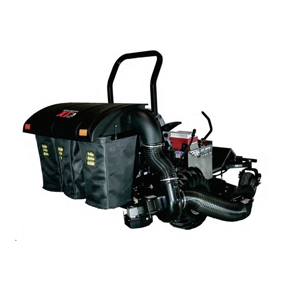
- Page 1 DESIGNED FOR: Classic Xcaliber 2960/3360 3366 Model #: 38131504 Model #: 38131503 60” Decks 66” Decks 2013 - 2011 OPERATOR’S MANUAL ASSEMBLY OPERATION MAINTENANCE MANUAL PART#: Q0459 REV: 0...
-
Page 2: Table Of Contents
XT GRASS COLLECTION SYSTEM TABLE OF CONTENTS SECTION PAGE SECTION PAGE Safety - - - - - - - - - - - - - - - - - - - - - - - - - - - - - - 2 2-14 Upper Hose Installation - - - - - - - - - - - - - - - - 17 Safety Alert Symbols - - - - - - - - - - - - - - - - - - - - - - 3 2-15 Lower Hose To Blower Cone Installation- - - - - - 17... -
Page 3: Safety Alert Symbols
SAFETY WARNING! NEVER operate the mower unless the discharge guard and either the deflector assembly or the vacuum collector adapter are fastened securely in place. WARNING! Do not work around the mower deck boot or the blower area until you are certain that the mower blades and the blower impeller have stopped rotating. -
Page 4: Warranty
1. NO SERVICE CENTER WARRANTY. The selling Service Center makes no warranty on his own on any item warranted by Dixie Chopper unless he delivers to purchaser a separate written warranty certificate specifically warranting the item. The dealer has no authority to make any representation or promise on behalf of Dixie Chopper or to modify the terms of this warranty in any way. -
Page 5: Introduction And Description
Section I - INTRODUCTION AND DESCRIPTION 1-1 Introduction 1-2 Description Your collection system has been designed to give you a The grass collection system is designed for turf low maintenance, simple, and effective way to collect the maintenance where there is a need to collect the grass grass clippings from your mower. -
Page 6: Installation For Use
NOTE: The mower deck PTO belt must be removed damage may occur. Refer to Figure 2-1c. from the electric clutch before continuing with the installation. Refer to your Dixie Chopper mower owner’s Upon pressing the engine pulley to the clutch, replace manual for instructions on PTO belt removal. -
Page 7: Pto Mount Plate Assembly Installation
2-2 PTO Mount Plate Assembly Installation Position the PTO mount plate assembly P#(A1871) on the right rear frame of the mower as shown in Figure 2- 2a. Secure the PTO mount plate assembly R.O.P.S. using (1) 3/8”-16 x 2-1/8” x 2-5/8” P#(K1119) and (2) 3/8”-16 nylon flange lock nuts P#(K2038). -
Page 8: Pto Assembly Installation
2-3 PTO Assembly Installation Insert the PTO assembly P#(A1623) into the mounting slots on the PTO mount plate assembly. Secure the PTO assembly with (1) PTO mount pin P#(B0274) and (1) hair pin clip P#(K0086). Refer to Figure 2-3. Attach the PTO handle assembly P#(A1142) to the PTO assembly using (3) 1/4”-20 x 3/4”... -
Page 9: Belt Installation
Connect the kevlar cord belt 78” P#(M0274) from the 2-4 Belt Installation and Adjustment engine pulley to the lower gear box pulley (Figure 2-4d). Loosen the (4) bolts P#(K1191), (2) on each side, that Figure 2-4d secure the gear box assembly to the PTO assembly Connect Belt P#(A1803) (Figure 2-4a and 2-4b). -
Page 10: Cam Assembly Adjustment
2-5 Cam Assembly Adjustment The cam assembly P#(A0422), which controls the blower belt tension, comes from the factory pre-adjusted. If the belt is too tight or becomes too loose, remove the hair pin clip P#(K0099) from the belt tension rod P#(K0326) and pull the “L”... -
Page 11: Lower Main Frame & Lower Frame Assembly Installation
Position the lower frame assembly P#(A1872) as shown 2-7 Lower Main Frame and Lower in Figure 2-7b. Secure the lower frame assembly to the Frame Assembly Installation lower main frame using (2) 1/2”-13 x 1-1/4” HHCS P#(K1232) and (2) 1/2”-13 nylon flange locknuts P#(K2012). -
Page 12: Upper Frame Assembly Installation
2-8 Upper Frame Assembly Installation NOTE: During this step, it is suggested that two people install the upper frame to the lower mount tube. Lift the upper frame assembly P#(A1058) above the lower frame assembly and lower the top assembly onto the two vertical tubes. -
Page 13: Top Assembly To Upper Frame Assembly Installation
2-9 Top Assembly To Upper Frame Assembly Installation Position the top assembly P#(A1187) above the upper frame assembly as shown in Figure 2-9. Fasten the top assembly to the upper frame assembly using (2) 5/16”- 18 x 2-1/2” HHCS P#(K0125) and (2) 5/16”-18 nylon flange locknuts P#(K2516). -
Page 14: Hose Clamp Preparation
Step 3: Using a flat file or disc grinder, remove 2-11 Hose Clamp Preparation sharp edges from clamp cut in Step 2. Refer to Figure 2-11d. CAUTION Figure 2-11d Note: To prevent injury, wear safety gear when cutting or grinding hose clamps. Remove Sharp Edge From Hose Clamp The hose clamps P#(J1000), provided with... -
Page 15: Boot To Mower Deck Installation
Classic Deck Plate Mounting Locations 2-12 Boot To Mower Deck Installation Refer to Figure 2-12c for Classic deck plate mounting NOTE: Remove all grass deflector and/or mulching locations. hardware from the mower deck before proceeding. Figure 2-12c Classic 50” & 60” Models Classic 50”... -
Page 16: Boot To Mower Deck Installation
2-12 Boot To Mower Deck Installation Continued Align the holes in the boot plate with the holes in the deck mount plate. Insert the boot rod P#(B0333) into the mounting holes and secure with (1) hair pin clip NOTE: Remove all grass deflector and/or mulching P#(K0099). -
Page 17: Length Of Hose Adjustment
2-13 Length Of Hose Adjustment 2-15 Lower Hose To Blower Cone The hoses in steps 2-14 and 2-15 must be cut to fit your Installation machine. Follow steps 2-14 and 2-15. Do not cut the Slide a pre-assembled hose clamp P#(J1000) over both hoses until you have tried to fit them on your machine. -
Page 18: Impeller Blade Removal And Replacement
2-17 Impeller Blade Removal/Replacement Tips on removing impeller blade; To gain impeller blade (#1) access, first remove the blower cone (#2) from the blower housing, located on 1 - Try carefully hitting the base of the impeller blade (#1), between each vein (#12), with a rubber mallet to the PTO assembly P#(A1821), by removing two blower loosen the taper-lock bushing hold. -
Page 19: Weight Kit Installation
2-18 Weight Kit Installation Using two people, lift the weight bar P#(B2220) into NOTE: It is recommended that someone assist you in position. Secure the weight bar to the left and right the weight kit installation procedure. weight brackets using (2) 1/2”-13 x 4-1/4” u-bolts P#(K0331) and (4) 1/2”-13 nylon flange locknuts Remove the front bumper and hardware from the mower P#K0212). -
Page 20: Installation/Removal Of Collection Bags
2-19 Installation/Removal Of Figure 2-19c Collection Bags Plastic Top IMPORTANT! To prevent bag wear, install (2) red plastic end caps P#(J0274), as shown in Figure 2-19a, on each bag ring before installing bags. Figure 2-19a Bag Ring Red Plastic End Caps Fasten Draw -Latch Here &... -
Page 21: Exploded Part Views And Assemblies
Exploded Parts View A1187 Top Assembly Item # Doc # Title V0022 PRO 3 BAGGER TOP B0676 Hinge Stop Pl. K0114 BLACK PLASTIC RIVET C0069 DUST GUARD BRACE K1030 1/4"-20 x 1-1/4" CARRIAGE BOLT J4009 SHORT RUBBER STRAP W/ S HOOK K0037 1/4"... - Page 22 Exploded Parts View A1623 PTO Assembly...
- Page 23 PTO Parts List A1623 PTO Assembly Item # Part # Desc. Qty. A1623 PTO ASSEMBLY A0429 GEAR BOX ASSEMBLY K0348 3/8"-16 x 2" ALL THREAD HHCS K0047 3/8" Flat Washer 1.00 OD x .446 ID x .075 T K0353 1/4"-20 x 1/2" HHSTS K1159 5/16"-18 x 2"...
-
Page 26: Operating Instructions
SECTION III 3-3 Disengagement Of The Blower OPERATING INSTRUCTIONS A. To disengage the blower, rotate the engagement 3-1 General Safety handle towards the mower. Only qualified people familiar with this operator’s manual WARNING: The blower will continue to spin. DO NOT and the mower’s operator’s manual should operate this TOUCH the blower, pulleys, or the belt until the tractor is machine. -
Page 27: Lubrication
Repair or replace before the next use. Any repairs to your collection system. If for any reason your replacement component installed during repair shall Dixie Chopper dealer is unable to service your collection include the component’s current safety decal specified system or supply replacement parts, contact Dixie by the manufacturers to be affixed to the component. -
Page 28: Safety Decals
SAFETY DECALS To promote safe operation, Dixie Chopper supplies safety decals on all products manufactured. Damage can occur to safety decals either through shipment, use or reconditioning. Contact your local Service Center for replacement decals. Part #: R1051 Warning: Hearing Protection Label... -
Page 29: Torque Specifications
D. Chopper... - Page 30 Contact: service@dixiechopper.com 765-246-6191 FAX 765-246-6017...
Need help?
Do you have a question about the 38131504 and is the answer not in the manual?
Questions and answers