Table of Contents
Advertisement
Advertisement
Table of Contents

Subscribe to Our Youtube Channel
Related Manuals for DFI 848P-AL


Summary of Contents for DFI 848P-AL
- Page 1 848P-AL 848P-A Rev. C+ System Board User’s Manual 76820352...
- Page 2 Copyright This publication contains information that is protected by copy- right. No part of it may be reproduced in any form or by any means or used to make any transformation/adaptation without the prior written permission from the copyright holders. This publication is provided for informational purposes only.
-
Page 3: Fcc And Doc Statement On Class B
Battery: • Danger of explosion if battery incorrectly replaced. • Replace only with the same or equivalent type recommend by the manufacturer. • Dispose of used batteries according to the battery manufac- turer’s instructions. FCC and DOC Statement on Class B This equipment has been tested and found to comply with the limits for a Class B digital device, pursuant to Part 15 of the FCC rules. -
Page 4: System Board
The autorun screen (Mainboard Utility CD) will appear. Click the “TOOLS” icon then click “Manual” on the main menu. System Board This user’s manual is for the 848P-AL and 848P-A system boards. The only difference between these boards is the 848P-AL system board supports onboard LAN. -
Page 5: Table Of Contents
Table of Contents Chapter 1 - Introduction 1.1 Features and Specifications................. 1.2 Hyper-Threading Technology Functionality Requirements... 1.3 Package Checklist......................Chapter 2 - Hardware Installation System Board Layout .................... System Memory......................CPU.............................. Jumper Settings....................... Rear Panel I/O Ports....................I/O Connectors......................Chapter 3 - BIOS Setup 3.1 Award BIOS Setup Utility.................. - Page 6 Introduction Chapter 4 - Supported Softwares 4.1 Desktop Management Interface..............4.2 Drivers, Utilities and Software Applications........ 4.3 3D Audio Configuration..................4.4 Installation Notes......................Appendix A - Enabling the Hyper-Threading T echnology A.1 Enabling the Hyper-Threading Technology........Appendix B - System Error Messages B.1 POST Beep........................
-
Page 7: Features And Specifications
Introduction Chapter 1 - Introduction 1.1 Features and Specifications 1.1.1 Features Chipset • Intel 848P chipset ® ® Intel 848P Memory Controller Hub (MCH) ® Intel 82801EB I/O Controller Hub (ICH5) Processor The system board is equipped with Socket 478 for installing one of the following supported processors. - Page 8 Introduction Density 128 Mbit 256 Mbit 512 Mbit Density Width SS/DS SS/DS SS/DS SS/DS SS/DS Single/Double SS/DS 128/256MB 64MB/NA 256/512MB 128MB/NA 512/1024MB 256MB/NA 184-pin DDR Expansion Slots • 1 AGP slot • 5 PCI slots AGP (Accelerated Graphics Port) • Supports AGP 3.0 (AGP 4x and 8x) and AGP 2.0 (AGP 1x and 4x) spec.
- Page 9 (2-channel) jack support 6-channel audio output. Onboard LAN Features (848P-AL only) • Realtek RTL8101L fast ethernet controller • Integrated IEEE 802.3, 10BASE-T and 100BASE-TX compatible •...
- Page 10 Introduction SATA IDE Interface • Two SATA (Serial ATA) interfaces which are compliant with SATA 1.0 specification (1.5Gbps interface) Serial ATA is a storage interface that is compliant with SATA 1.0 specification. With speed of up to 1.5Gbps, it improves hard drive performance even in data intensive environments such as audio/ video, consumer electronics and entry-level servers.
- Page 11 • 1 DB-9 serial port • 1 DB-25 parallel port • 4 USB 2.0/1.1 ports • 1 RJ45 LAN port (848P-AL only) • 2 S/PDIF RCA jacks (S/PDIF-in and S/PDIF-out) • 3 audio jacks: line-out, line-in and mic-in • 2 audio jacks for center/bass and rear out...
- Page 12 Introduction I/O Connectors • 2 connectors for 4 additional external USB 2.0/1.1 ports • 1 front audio connector for external line-out and mic-in jacks • 1 CD-in internal audio connector • 1 S/PDIF connector for optical cable connection • 1 connector for IrDA interface •...
- Page 13 Introduction Wake-On-LAN This feature allows the network to remotely wake up a Soft Power Down (Soft-Off) PC. It is supported via the onboard LAN port, via a PCI LAN card that uses the PCI PME (Power Manage- ment Event) signal or via a LAN card that uses the Wake-On- LAN connector.
- Page 14 Introduction ACPI The system board is designed to meet the ACPI (Advanced Con- figuration and Power Interface) specification. ACPI has energy sav- ing features that enables PCs to implement Power Management and Plug-and-Play with operating systems that support OS Direct ®...
-
Page 15: Hyper-Threading Technology Functionality Requirements
Introduction 1.2 Hyper-Threading Technology Functionality Requirements Enabling the functionality of Hyper-Threading Technology for your computer system requires ALL of the following platforms. Components: ® ® • CPU - an Intel Pentium 4 Processor with HT Technology ® • Chipset - an Intel chipset that supports HT Technology •... -
Page 16: Chapter 2 - Hardware Installation
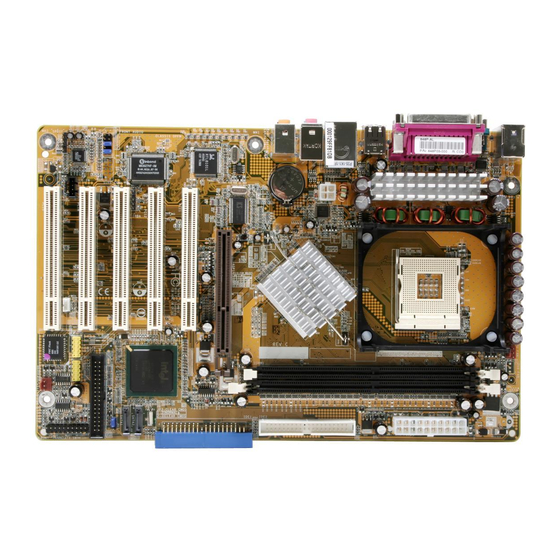
Hardware Installation Chapter 2 - Hardware Installation 2.1 System Board Layout 848P-AL (Supports onboard LAN) -
Page 17: Hardware Installation
Hardware Installation 848P-A Note: The illustrations on the following pages are based on the system board that supports onboard LAN. -
Page 18: System Memory
Hardware Installation Warning: Electrostatic discharge (ESD) can damage your system board, proces- sor, disk drives, add-in boards, and other components. Perform the upgrade instruction procedures described at an ESD workstation only. If such a station is not available, you can provide some ESD protection by wearing an antistatic wrist strap and attaching it to a metal part of the system chassis. -
Page 19: Installing The Dim Module
Hardware Installation 2.2.1 Installing the DIM Module A DIM module simply snaps into a DIMM socket on the system board. Pin 1 of the DIM module must correspond with Pin 1 of the socket. Notch Pin 1 1. Pull the “tabs” which are at the ends of the socket to the side. -
Page 20: Cpu
Hardware Installation 2.3 CPU 2.3.1 Overview The system board is equipped with a surface mount 478-pin CPU socket. This socket is exclusively designed for installing an Intel processor. 2.3.2 Installing the CPU 1. Locate Socket 478 on the system board. 2. - Page 21 Hardware Installation 3. Position the CPU above the socket then align the gold mark on the corner of the CPU (designated as pin 1) with pin 1 of the socket. Important: Handle the CPU by its edges and avoid touching the pins. Gold mark Pin 1 4.
-
Page 22: Installing The Fan And Heat Sink
Hardware Installation 5. Once the CPU is in place, push down the lever to lock the socket. The lever should click on the side tab to indicate that the CPU is completely secured in the socket. 2.3.3 Installing the Fan and Heat Sink The CPU must be kept cool by using a CPU fan with heatsink. - Page 23 Hardware Installation 1. The system board comes with the retention module base al- ready installed. Retention Retention hole hole Retention Retention hole hole Retention module base 2. Position the fan / heat sink and retention mechanism assembly on the CPU, then align and snap the retention legs’ hooks to the retention holes at the 4 corners of the retention module base.
- Page 24 Hardware Installation 3. The retention levers at this time remains unlocked as shown in the illustration below. Retention lever Retention lever 4. Move the retention levers to their opposite directions then push them down. This will secure the fan / heat sink and re- tention mechanism assembly to the retention module base.
-
Page 25: Jumper Settings
Hardware Installation 2.4 Jumper Settings 2.4.1 Jumper Settings for Clearing CMOS Data 1-2 On: Normal 2-3 On: (default) Clear CMOS Data If you encounter the following, a) CMOS data becomes corrupted. b) You forgot the supervisor or user password. c) You are unable to boot-up the computer system because the proc- essor’s ratio/clock was incorrectly set in the BIOS. - Page 26 Hardware Installation 4. After powering-on the system, press <Del> to enter the main menu of the BIOS. 5. Select the Frequency/Voltage Control submenu and press <Enter>. 6. Set the “CPU Clock Ratio” or “Clock By Slight Adjust” field to its default setting or an appropriate frequency ratio or bus clock.
-
Page 27: Rear Panel I/O Ports
• PS/2 mouse port • PS/2 keyboard port • Parallel port • COM port • S/PDIF-in • S/PDIF-out • USB ports • LAN port (848P-AL only) • Mic-in jack • Line-in jack • Line-out jack • Center/Bass jack • Rear out jack... - Page 28 Hardware Installation 2.5.1 PS/2 Mouse and PS/2 Keyboard Ports PS/2 Mouse PS/2 Keyboard The system board is equipped with an onboard PS/2 mouse (Green) and PS/2 keyboard (Purple) ports - both at location CN1 of the system board. The PS/2 mouse port uses IRQ12. If a mouse is not connected to this port, the system will reserve IRQ12 for other expansion cards.
-
Page 29: Serial Port
Hardware Installation 2.5.2 Serial Port The system board is equipped with an onboard serial port (Teal/ Turquoise) at location CN6 of the system board. It is a RS-232C asynchronous communication por t with 16C550A-compatible UART that can be used with a modem, serial printer, remote display terminal or other serial devices. -
Page 30: Parallel Port
Hardware Installation 2.5.3 Parallel Port Parallel The system board has a standard parallel port (Burgundy) at lo- cation CN9 for interfacing your PC to a parallel printer. It sup- ports SPP, ECP, EPP and PntMode. Setting Function Allows normal speed operation (Standard Parallel Port) but in one direction only. - Page 31 Hardware Installation 2.5.4 S/PDIF S/PDIF-in S/PDIF-out SPDIF out SPDIF in The system board is equipped with an onboard S/PDIF-in RCA jack (red) and a S/PDIF-out RCA jack (yellow) at locations CN2 and CN3 respectively. The S/PDIF connector at location J3 is for optical S/PDIF cable connection.
-
Page 32: Universal Serial Bus Ports
Hardware Installation 2.5.5 Universal Serial Bus Ports USB 2 USB 1 USB 4 USB 3 USB 5-6 USB 7-8 Four onboard USB 2.0/1.1 ports (Black) are at locations CN7 (USB 1-2) and CN8 (USB 3-4) of the system board. J8 (USB 5-6) and J10 (USB 7-8) connectors allow you to con- nect 4 additional USB 2.0/1.1 por ts. - Page 33 Hardware Installation If you are using a USB 2.0 device, install the “Intel USB 2.0 Driv- ers”. Refer to chapter 4 for more information. Wake-On-USB Keyboard The Wake-On-USB Keyboard function allows you to use a USB keyboard to wake up a system from the S3 (STR - Suspend To RAM) state.
- Page 34 2.5.6 RJ45 Fast-Ethernet Port (848P-AL only) RJ45 LAN The 848P-AL system board is equipped with an onboard RJ45 fast-ethernet LAN port at location CN8 of the system board. It allows the system board to connect to a local area network by means of a network hub.
- Page 35 Hardware Installation 2.5.7 Audio Mic-in Line-in Line-out Center/Bass Rear out Front audio Mic-in, Line-in and Line-out The mic-in, line-in and line-out jacks are at location CN4 of the system board. A jack is a one-hole connecting interface for insert- ing a plug. •...
- Page 36 Hardware Installation • Line-out Jack (Lime) This jack is used to connect external speakers for audio output from the system board. Using this jack disables the front au- dio’s line-out function. Center/Bass and Rear Out Jacks Center/Bass and Rear Out Jacks (CN5) support 4 audio output signals: center channel, subwoofer, rear right channel and rear left channel.
-
Page 37: I/O Connectors
Hardware Installation 2.6 I/O Connectors 2.6.1 CD-in Internal Audio Connector Ground Ground Left audio Right audio channel channel The CD-in (J5) connector is used to receive audio from a CD- ROM drive, TV tuner or MPEG card. -
Page 38: Floppy Disk Drive Connector
Hardware Installation 2.6.2 Floppy Disk Drive Connector The system board is equipped with a shrouded floppy disk drive connector that supports two standard floppy disk drives. To pre- vent improper floppy cable installation, the shrouded floppy disk header has a keying mechanism. The 34-pin connector on the floppy cable can be placed into the header only if pin 1 of the connector is aligned with pin 1 of the header. -
Page 39: Serial Ata Connectors
Hardware Installation 2.6.3 Serial ATA Connectors SATA 2 SATA 1 Connect one end of the SATA cable to J13 (SATA 2) or J14 (SATA 1) and the other end to your serial ATA device. BIOS Setting Configure the onboard Serial ATA in the Integrated Peripherals submenu (“OnChip IDE Device”... -
Page 40: Ide Disk Drive Connector
Hardware Installation 2.6.4 IDE Disk Drive Connector IDE 2 IDE 1 IDE 2 IDE 1 The system board is equipped with two shrouded PCI IDE head- ers that will interface four Enhanced IDE (Integrated Drive Elec- tronics) disk drives. To prevent improper IDE cable installation, each shrouded PCI IDE header has a keying mechanism. - Page 41 Hardware Installation Note: Refer to your disk drive user’s manual for information about selecting proper drive switch settings. Adding a Second IDE Disk Drive When using two IDE drives, one must be set as the master and the other as the slave. Follow the instructions provided by the drive manufacturer for setting the jumpers and/or switches on the drives.
-
Page 42: Irda Connector
Hardware Installation 2.6.5 IrDA Connector IRRX N. C. Ground IRTX Connect your IrDA cable to connector J6 on the system board. Note: The sequence of the pin functions on some IrDA cable may be reversed from the pin function defined on the system board. Make sure to connect the cable to the IrDA connector according to their pin functions. -
Page 43: Cooling Fan Connectors
Hardware Installation 2.6.6 Cooling Fan Connectors Power Ground N. C. CPU fan Power Ground N. C. Chassis fan Connect the CPU fan’s cable connector to the CPU fan connec- tor (J9) on the system board. The chassis fan connector (J12) is used to connect an additional cooling fan. - Page 44 Hardware Installation 2.6.7 Wake-On-LAN Connector Ground +5VSB Your LAN card package should include a cable. Connect one end of the cable to the wakeup header on the card and the other end to location J7 on the system board. The network will detect Magic Packet and assert a wakeup signal to power-up the system.
- Page 45 Hardware Installation 2.6.8 DIMM Standby Power LED DIMM Standby Power LED This DIMM Standby Power LED will turn red when the system’s power is on or when it is in the Suspend state (Power On Sus- pend or Suspend to RAM). It will not light when the system is in the Soft-Off state.
-
Page 46: Power Connectors
Hardware Installation 2.6.9 Power Connectors +12V 5VSB PW-OK Ground Ground Ground Ground Ground PS-ON Ground Ground -12V 3.3V 3.3V 3.3V +12V Ground Ground +12V We recommend that you use a power supply that complies with the ATX12V Power Supply Design Guide Version 1.1. An ATX12V power supply has a standard 20-pin ATX main power connector and a 4-pin +12V power connector that must be inserted onto CN11 and CN10 connectors respectively. -
Page 47: Front Panel Connectors
Hardware Installation 2.6.10 Front Panel Connectors PWR-LED HD-LED RESET ATX-SW SPEAKER 19 20 HD-LED: Primary/Secondary IDE LED This LED will light when the hard drive is being accessed. RESET: Reset Switch This switch allows you to reboot without having to power off the system thus prolonging the life of the power supply or sys- tem. - Page 48 Hardware Installation PWR-LED: Power/Standby LED When the system’s power is on, this LED will light. When the system is in the S1 (POS - Power On Suspend) or S3 (STR - Suspend To RAM) state, it will blink every second. Note: If a system did not boot-up and the Power/Standby LED did not light after it was powered-on, it may indicate that the CPU...
-
Page 49: Chapter 3 - Bios Setup
BIOS Setup Chapter 3 - BIOS Setup 3.1 Award BIOS Setup Utility The Basic Input/Output System (BIOS) is a program that takes care of the basic level of communication between the processor and peripherals. In addition, the BIOS also contains codes for vari- ous advanced features found in this system board. -
Page 50: Standard Cmos Features
BIOS Setup 3.1.1 Standard CMOS Features Use the arrow keys to highlight “Standard CMOS Features” and press <Enter>. A screen similar to the one below will appear. The settings on the screen are for reference only. Your version may not be identical to this one. -
Page 51: Bios Setup
BIOS Setup 3.1.1.3 IDE Channel 0 Master, IDE Channel 0 Slave, IDE Channel 1 Master and IDE Channel 1 Slave Move the cursor to the “IDE Channel 0 Master”, “IDE Channel 0 Slave”, “IDE Channel 1 Master” or “IDE Channel 1 Slave” field, then press <Enter>. - Page 52 BIOS Setup Access Mode For hard drives larger than 528MB, you would typically select the LBA type. Certain operating systems require that you select CHS or Large. Please check your operating system’s manual or Help desk on which one to select. Capacity Displays the approximate capacity of the disk drive.
- Page 53 BIOS Setup 3.1.1.5 Video This field selects the type of video adapter used for the primary system monitor. Although secondary monitors are supported, you do not have to select the type. The default setting is EGA/VGA. EGA/VGA Enhanced Graphics Adapter/Video Graphics Array. For EGA, VGA, SVGA and PGA monitor adapters.
- Page 54 BIOS Setup 3.1.1.8 Extended Memory Displays the amount of extended memory detected during boot- 3.1.1.9 Total Memory Displays the total memory available in the system.
-
Page 55: Advanced Bios Features
BIOS Setup 3.1.2 Advanced BIOS Features The Advanced BIOS Features allows you to configure your system for basic operation. Some entries are defaults required by the system board, while others, if enabled, will improve the performance of your system or let you set some features according to your preference. The screen above list all the fields available in the Advanced BIOS Features submenu, for ease of reference in this manual. - Page 56 BIOS Setup ® ® 3.1.2.3 Hyper-Threading Technology (for Intel Pentium 4 Processor with Hyper-Threading Technology only) ® This field is used to enable the functionality of the Intel ® Pentium 4 Processor with Hyper-Threading Technology and will appear only when using this processor. 3.1.2.4 Quick Power On Self Test This field speeds up Power On Self Test (POST) whenever the system is powered on.
- Page 57 BIOS Setup 3.1.2.9 Boot Up Floppy Seek When enabled, the BIOS will check whether the floppy disk drive installed is 40 or 80 tracks. Note that the BIOS cannot distinguish between 720K, 1.2M, 1.44M and 2.88M drive types as they are all 80 tracks.
- Page 58 BIOS Setup 3.1.2.14 Security Option This field determines when the system will prompt for the pass- word - everytime the system boots or only when you enter the BIOS setup. Set the password in the Set Supervisor/User Pass- word submenu. System The system will not boot and access to Setup will be denied unless the correct password is entered at the prompt.
- Page 59 BIOS Setup 3.1.2.19 Report No FDD For WIN 95 The options are Yes and No. 3.1.2.20 Full Screen Logo Show This field is applicable only if you want a particular logo to ap- pear during system boot-up. Enabled The logo will appear in full screen during system boot-up.
-
Page 60: Advanced Chipset Features
BIOS Setup 3.1.3 Advanced Chipset Features The settings on the screen are for reference only. Your version may not be identical to this one. This section gives you functions to configure the system based on the specific features of the chipset. The chipset manages bus speeds and access to system memory resources. - Page 61 BIOS Setup Manual If you want your system to run at a performance better than the one “by SPD”, select “Manual” then select the best option in the “CAS Latency Time” to “DRAM RAS# Precharge” fields. 3.1.3.2 CAS Latency Time This field is used to select the local memory clock periods.
- Page 62 BIOS Setup 3.1.3.8 Video BIOS Cacheable As with caching the system BIOS, enabling the Video BIOS cache will allow access to video BIOS addresssed at C0000H to C7FFFH to be cached, if the cache controller is also enabled. The larger the range of the Cache RAM, the faster the video perform- ance.
-
Page 63: Integrated Peripherals
BIOS Setup 3.1.4 Integrated Peripherals The settings on the screen are for reference only. Your version may not be identical to this one. 3.1.4.1 OnChip IDE Device Move the cursor to this field and press <Enter>. The following screen will appear. The settings on the screen are for reference only. - Page 64 BIOS Setup IDE HDD Block Mode Enabled The IDE HDD uses the block mode. The system BIOS will check the hard disk drive for the maximum block size the system can transfer. The block size will depend on the type of hard disk drive.
- Page 65 BIOS Setup IDE Primary Master/Slave UDMA and IDE Secondary Master/ Slave UDMA These fields allow you to set the Ultra DMA in use. When Auto is selected, the BIOS will select the best available option after checking your hard drive or CD-ROM. Auto The BIOS will automatically detect the settings for you.
- Page 66 BIOS Setup 3.1.4.2 Onboard Device Move the cursor to this field and press <Enter>. The following screen will appear. The settings on the screen are for reference only. Your version may not be identical to this one. USB Controller Enabled Enables the onboard USB. You can further configure the USB in the “USB 2.0 Controller”...
- Page 67 BIOS Setup Onboard LAN Control (848P-AL only) This field is used to enable or disable the onboard LAN control- ler. 3.1.4.3 Super IO Device Move the cursor to this field and press <Enter>. The following screen will appear. The settings on the screen are for reference only. Your version may not be identical to this one.
- Page 68 BIOS Setup Onboard SIR Select This field is used to select an I/O address for the IrDA device. UART2 Mode Select This field is used to select the type of IrDA standard supported by your IrDA device. For better transmission of data, your IrDA peripheral device must be within a 30 angle and within a dis- tance of 1 meter.
- Page 69 BIOS Setup ECP (Extended Capabilities Port) Allows parallel port to operate in bidirectional mode and at a speed faster than the normal mode’s data transfer rate. EPP (Enhanced Parallel Port) Allows bidirectional parallel port operation at maximum speed. PntMode Allows parallel port to operate in bipolar mode. If you selected EPP, the “EPP Mode Select”...
-
Page 70: Power Management Setup
BIOS Setup 3.1.5 Power Management Setup The Power Management Setup allows you to configure your system to most effectively save energy. The settings on the screen are for reference only. Your version may not be identical to this one. 3.1.5.1 ACPI Function This function should be enabled only in operating systems that ®... - Page 71 BIOS Setup 3.1.5.3 Power Management This field allows you to select the type (or degree) of power saving by changing the length of idle time that elapses before the HDD Power Down field is activated. Min Saving Minimum power saving time for the HDD Power Down = 15 min.
- Page 72 BIOS Setup 3.1.5.8 Soft-Off by PWR-BTTN This field allows you to select the method of powering off your system. Delay 4 Sec. Regardless of whether the Power Management function is enabled or disabled, if the power button is pushed and released in less than 4 sec, the system enters the Suspend mode.
- Page 73 BIOS Setup 3.1.5.10 PM Wake Up Events Move the cursor to this field and press <Enter>. The following screen will appear. The settings on the screen are for reference only. Your version may not be identical to this one. Resume on PCI Event Enabled This field should be set to Enabled only if your PCI card such as LAN card or modem card uses the PCI...
- Page 74 BIOS Setup Resume On LAN If you are using a LAN card that supports the remote wake up function, set this field to Enabled. The will allow the network to remotely wake up a Soft Power Down (Soft-Off) PC. However, if your system is in the Suspend mode, you can wake up the system only through an IRQ or DMA interrupt.
- Page 75 BIOS Setup Time (hh:mm:ss) Alarm This is used to set the time you would like the system to power- on. If you want the system to power-on everyday as set in the “Date (of Month) Alarm” field, the time set in this field must be later than the time of the RTC set in the Standard CMOS Fea- tures submenu.
- Page 76 BIOS Setup KB Power On Hot Key This field is used to select a function key that you would like to use to power-on the system.
-
Page 77: Pnp/Pci Configurations
BIOS Setup 3.1.6 PnP/PCI Configurations This section describes configuring the PCI bus system. It covers some very technical items and it is strongly recommended that only experienced users should make any changes to the default settings. The settings on the screen are for reference only. Your version may not be identical to this one. - Page 78 BIOS Setup 3.1.6.3 IRQ Resources Move the cursor to this field and press <Enter>. The “IRQ-3” to “IRQ-15” fields will appear. Set each system interrupt to either PCI Device or Reserved. The settings on the screen are for reference only. Your version may not be identical to this one.
-
Page 79: Frequency/Voltage Control
BIOS Setup 3.1.7 Frequency/Voltage Control The settings on the screen are for reference only. Your version may not be identical to this one. 3.1.7.1 CPU Clock Ratio This field is used to select the frequency ratio of the processor. Important: The frequency ratio of some processors may have been locked by the manufacturer. - Page 80 BIOS Setup 3.1.7.5 Clock By Slight Adjust This field provides several options for selecting the external sys- tem bus clock of the processor. The available options allow you to adjust the processor’s bus clock by 1MHz increment. Important: Selecting an external bus clock other than the default setting may result to the processor’s or system’s instability and are not guaranteed to provide better system performance.
- Page 81 BIOS Setup 3.1.7.6 CPU Vcore Adjust This field allows you to manually select higher core voltage sup- plied to the CPU. If you wish to use the CPU’s default core volt- age, leave this field in its default setting. The CPU’s Vcore will be generated according to the CPU VID configuration.
-
Page 82: Load Fail-Safe Defaults
BIOS Setup 3.1.8 Load Fail-Safe Defaults The “Load Fail-Safe Defaults” option loads the troubleshooting default values permanently stored in the ROM chips. These settings are not optimal and turn off all high performance features. You should use these values only if you have hardware problems. Highlight this option in the main menu and press <Enter>. -
Page 83: Load Optimized Defaults
BIOS Setup 3.1.9 Load Optimized Defaults The “Load Optimized Defaults” option loads optimized settings from the BIOS ROM. Use the default values as standard values for your system. Highlight this option in the main menu and press <Enter>. Type <Y> and press <Enter> to load the Setup default values. -
Page 84: Set Supervisor Password
BIOS Setup 3.1.10 Set Supervisor Password If you want to protect your system and setup from unauthorized entry, set a supervisor’s password with the “System” option selected in the Advanced BIOS Features. If you want to protect access to setup only, but not your system, set a supervisor’s password with the “Setup”... -
Page 85: Set User Password
BIOS Setup 3.1.11 Set User Password If you want another user to have access only to your system but not to setup, set a user’s password with the “System” option selected in the Advanced BIOS Features. If you want a user to enter a password when trying to access setup, set a user’s password with the “Setup”... -
Page 86: Save & Exit Setup
BIOS Setup 3.1.12 Save & Exit Setup When all the changes have been made, highlight “Save & Exit Setup” and press <Enter>. Type “Y” and press <Enter>. The modifications you have made will be written into the CMOS memory, and the system will reboot. You will once again see the initial diagnostics on the screen. -
Page 87: Exit Without Saving
BIOS Setup 3.1.13 Exit Without Saving When you do not want to save the changes you have made, highlight “Exit Without Saving” and press <Enter>. Type “Y” and press <Enter>. The system will reboot and you will once again see the initial diagnostics on the screen. If you wish to make any changes to the setup, press <Ctrl>... -
Page 88: Updating The Bios
3.2 Updating the BIOS To update the BIOS, you will need the new BIOS file and a flash utility, AWDFLASH.EXE. You can download them from DFI’s web site or contact technical support or your sales representative. 1. Save the new BIOS file along with the flash utility AWDFLASH.EXE to a floppy disk. - Page 89 BIOS Setup 6. The following will appear. Do You Want to Save BIOS (Y/N) This question refers to the current existing BIOS in your system. We recommend that you save the current BIOS and its flash utility; just in case you need to reinstall the BIOS. To save the current BIOS, press <Y>...
-
Page 90: Chapter 4 - Supported Softwares
Supported Software Chapter 4 - Supported Software 4.1 Desktop Management Interface (DMI) The system board comes with a DMI built into the BIOS. DMI, along with the appropriately networked software, is designed to make inventory, maintenance and troubleshooting of computer sys- tems easier. -
Page 91: Supported Software
Supported Software 4.1.2 Using the DMI Utility Award DMI Configuration Utility Copyright Award Software Inc, 1996 [Edit DMI] [Add DMI] [Load DMI File] [Save DMI File] BIOS *** BIOS Auto Detect *** System Enclosure/Chassis Type : BIOS Information Processor Handle : 0000 Memory Controller Vendor Name : Memory Module... - Page 92 Supported Software Add DMI 1. Use the ← or → arrow keys to select the Add DMI menu. 2. Highlight the item on the left screen that you would like to add by using the ↑ or ↓ arrow keys, then press <Enter>. 3.
-
Page 93: Drivers, Utilities And Software Applications
Supported Software 4.2 Drivers, Utilities and Software Applications The CD that came with the system board contains drivers, utilities and software applications required to enhance the performance of the system board. Inser t the CD into a CD-ROM drive. The autorun screen (Mainboard Utility CD) will appear. -
Page 94: Intel Chipset Software Installation Utility
Supported Software 4.2.1 Intel Chipset Software Installation Utility The Intel Chipset Software Installation Utility is used for updating Windows 98SE/2000/ME/XP's INF files so that the Intel chipset can be recognized and configured properly in the system. To install the utility, please follow the steps below. 1. -
Page 95: Audio Drivers
Supported Software 4.2.2 Audio Drivers The audio drivers are supported in the following operating sys- tems: Windows 98 SE, Windows ME, Windows 2000 and Windows To install the driver, please follow the steps below. 1. On the left side of the autorun screen, click the “AUDIO” icon. 2. - Page 96 Supported Software 3. The following screen will appear. 4. Follow the prompts on the screen to complete installation. 5. Reboot the system for the driver to take effect. Note: The 3D Audio Configuration software, which is an audio panel for setting basic audio configurations, will at the same time be installed into your system.
- Page 97 Supported Software 4.2.3 Intel USB 2.0 Drivers If you are using a USB 2.0 device, you must install the USB 2.0 driver. The drivers are supported in the following operating systems: Windows 98 SE, Windows ME and Windows 2000.
- Page 98 Supported Software Windows 2000 does not support auto-installation of the USB 2.0 driver. When you click “Intel USB 2.0 Drivers”, the “readme” screen will appear. 3. Follow the installation instructions shown on the screen. 4. Reboot the system for the driver to take effect. Important: ®...
- Page 99 Supported Software 4.2.4 LAN Drivers (848P-AL only) The LAN drivers suppor t autorun for the following operating systems: Windows 98 SE, Windows ME, Windows 2000 and Windows To install the driver, please follow the steps below.
- Page 100 Supported Software 4.2.5 McAfee VirusScan Online (English OS only) The McAfee VirusScan Online is the most reliable and convenient way of protecting your PC from computer viruses. When you install McAfee VirusScan Online, your computer is safe because it automatically scans for viruses and checks for virus updates so that PC protection stays up-to-date.
- Page 101 Supported Software 4.2.6 Microsoft DirectX 9 To install, please follow the steps below. 1. On the left side of the autorun screen, click the “TOOLS” icon. 2. Click “Microsoft DirectX 9” on the main menu. The following screen will appear. 3.
-
Page 102: Audio Configuration
Supported Software 4.3 3D Audio Configuration When you install the audio driver, the 3D Audio Configuration software will at the same time be installed into your system. 3D Audio Configuration is an audio panel for setting basic audio configurations. It allows you to configure 2-channel, 4-channel and 6- channel audio modes as well as configure the audio effects. - Page 103 Supported Software Speaker Output When you open 3D Audio Configuration, the default screen that appears is the Speaker Output. This is where you will configure analog output settings to speakers. S/PDIF This panel is used to configure S/PDIF output which provides a low- distor tion digital data transfer between audio devices.
- Page 104 Supported Software Microphone This panel is used to configure the microphone. Xear 3D Xear 3D is a sound technology for 2-channel virtual surround, adjustable multi-channel sound field, innovative listening mode, amazing sound effects and 3D positional audio. It has 3 functional blocks: Virtual Speaker Shifter, Sound Effect and Multi-channel Music Demo.
-
Page 105: Installation Notes
2. All steps or procedures to install software drivers are subject to change without notice as the softwares are occassionally updated. Please go to DFI's web site at "http://www.dfi.com/ support1/download2.asp" for the latest version of the drivers or software applications. -
Page 106: Appendix A - Enabling The Hyper-Threading T Echnology
Enabling Hyper-Threading Technology Appendix A - Enabling Hyper-Threading Technology A.1 Enabling Hyper-Threading Technology To enable the functionality of the Hyper-Threading Technology, please follow the requirements and steps below. Basically, the following ® ® presumes that you have already installed an Intel Pentium Processor with Hyper-Threading Technology. - Page 107 Enabling Hyper-Threading Technology Click the General tab. The processor shown under Computer should resemble the one shown below. Now click the Hardware tab then click Device Manager. The items shown under Computer and Processors should resemble the ones shown below.
- Page 108 Enabling Hyper-Threading Technology Lastly, press the <Ctrl> <Alt> and <Del> keys simultaneously. The Windows Task Manager dialog box will appear. Click the Performance tab. The diagram under CPU Usage History should resemble the one shown below.
-
Page 109: Appendix B - System Error Messages
System Error Message Appendix B - System Error Message When the BIOS encounters an error that requires the user to correct something, either a beep code will sound or a message will be displayed in a box in the middle of the screen and the message, PRESS F1 TO CONTINUE, CTRL-ALT-ESC or DEL TO ENTER SETUP, will be shown in the information box at the bottom. - Page 110 System Error Message setting than indicated in Setup. Determine which setting is correct, either turn off the system and change the jumper or enter Setup and change the VIDEO selection. FLOPPY DISK(S) fail (80) Unable to reset floppy subsystem. FLOPPY DISK(S) fail (40) Floppy type mismatch.
-
Page 111: Appendix C - Troubleshooting
Troubleshooting Appendix C - Troubleshooting C.1 Troubleshooting Checklist This chapter of the manual is designed to help you with problems that you may encounter with your personal computer. To efficiently troubleshoot your system, treat each problem individually. This is to ensure an accurate diagnosis of the problem in case a problem has multiple causes. -
Page 112: Power Supply
Troubleshooting The picture seems to be constantly moving. 1. The monitor has lost its vertical sync. Adjust the monitor’s vertical sync. 2. Move away any objects, such as another monitor or fan, that may be creating a magnetic field around the display. 3. -
Page 113: Hard Drive
Troubleshooting Hard Drive Hard disk failure. 1. Make sure the correct drive type for the hard disk drive has been entered in the BIOS. 2. If the system is configured with two hard drives, make sure the bootable (first) hard drive is configured as Master and the second hard drive is configured as Slave. - Page 114 Troubleshooting Serial Port The serial device (modem, printer) doesn’t output anything or is outputting garbled characters. 1. Make sure that the serial device’s power is turned on and that the device is on-line. 2. Verify that the device is plugged into the correct serial port on the rear of the computer.
Need help?
Do you have a question about the 848P-AL and is the answer not in the manual?
Questions and answers