Table of Contents
Advertisement
Advertisement
Table of Contents

Related Manuals for DFI KT600-AL


Summary of Contents for DFI KT600-AL
- Page 1 KT600-AL Rev. A+ System Board User’s Manual 78700345...
- Page 2 Copyright This publication contains information that is protected by copy- right. No part of it may be reproduced in any form or by any means or used to make any transformation/adaptation without the prior written permission from the copyright holders. This publication is provided for informational purposes only.
-
Page 3: Fcc And Doc Statement On Class B
Battery: • Danger of explosion if battery incorrectly replaced. • Replace only with the same or equivalent type recommend by the manufacturer. • Dispose of used batteries according to the battery manufac- turer’s instructions. FCC and DOC Statement on Class B This equipment has been tested and found to comply with the limits for a Class B digital device, pursuant to Part 15 of the FCC rules. - Page 4 Notice This user’s manual contains detailed information about the system board. If, in some cases, some information doesn’t match those shown in the multilingual manual, the multilingual manual should always be regarded as the most updated version. The multilingual manual is included in the system board package. To view the user’s manual, insert the CD into a CD-ROM drive.
-
Page 5: Table Of Contents
Table of Contents Chapter 1 - Introduction 1.1 Features and Specifications................. 1.2 Package Checklist......................Chapter 2 - Hardware Installation 2.1 System Board Layout ....................2.2 System Memory......................2.3 CPU..............................2.4 Jumper Settings......................... 2.5 Rear I/O Panel........................2.6 I/O Connectors....................... Chapter 3 - BIOS Setup 3.1 Award BIOS Setup Utility.................. - Page 6 Introduction Appendix A - Using the Suspend to RAM Function A.1 Using the Suspend to RAM Function............Appendix B - System Error Messages B.1 POST Beep........................B.2 Error Messages......................Appendix C - Troubleshooting C.1 Troubleshooting Checklist..................
-
Page 7: Features And Specifications
Introduction Chapter 1 - Introduction 1.1 Features and Specifications 1.1.1 Features Chipset ® • VIA chipset ® North bridge: VIA KT600 ® South bridge: VIA VT8237 Processor The system board is equipped with Socket-A for 462-pin PGA processor. It is also equipped with a switching voltage regulator that automatically detects 1.100V to 1.850V. - Page 8 Introduction Expansion Slots • 1 AGP slot • 5 PCI slots AGP (Accelerated Graphics Port) AGP is an interface designed to support high performance 3D graphics cards. It utilizes a dedicated pipeline to access system memory for texturing, z-buffering and alpha blending. The univer- sal AGP slot supports AGP 8x with up to 2.13GB/sec.
- Page 9 Introduction S/PDIF S/PDIF is a standard audio file transfer format that transfers digital audio signals to a device without having to be converted first to an analog format. This prevents the quality of the audio signal from degrading whenever it is converted to analog. S/PDIF is usu- ally found on digital audio equipment such as a DAT machine or audio processing device.
- Page 10 Introduction PCI Bus Master IDE Controller • Supports ATA/33, ATA/66, ATA/100 and ATA/133 hard drives • UDMA Modes 3, 4, 5 and 6 Enhanced IDE (data transfer rate up to 133MB/sec.) • Bus mastering reduces CPU utilization during disk transfer •...
-
Page 11: System Health Monitor Functions
Introduction Rear Panel I/O Ports (PC 99 color-coded connectors) • One mini-DIN-6 PS/2 mouse port • One mini-DIN-6 PS/2 keyboard port • Two DB-9 serial ports • One DB-25 parallel port • Four USB ports • One LAN port • Three audio jacks: line-out, line-in and mic-in Connectors •... - Page 12 Introduction 1.1.3 Intelligence CPU Temperature Protection The CPU Temperature Protection function has the capability of monitoring the CPU’s temperature during system boot-up. Once it has detected that the CPU’s temperature exceeded the “shut- down temperature” defined in the BIOS, the system will auto- matically power-off after 5 warning beeps.
- Page 13 Introduction Wake-On-Ring This feature allows the system that is in the Suspend mode or Soft Power Off mode to wake-up/power-on to respond to calls coming from an external modem or respond to calls from a modem PCI card that uses the PCI PME (Power Management Event) signal to remotely wake up the PC.
- Page 14 Introduction • If you are using the Wake-On-USB function for 3 or more USB ports, the 5VSB power source of your power supply must support ≥ 2A. RTC Timer to Power-on the System The RTC installed on the system board allows your system to automatically power-on on the set date and time.
-
Page 15: Package Checklist
Introduction 1.2 Package Checklist The system board package contains the following items: The system board A user’s manual One Serial ATA cable One IDE cable for ATA/33/66/100/133 IDE drives One 34-pin floppy disk drive cable One I/O shield One “Main Board Utility” CD If any of these items are missing or damaged, please contact your dealer or sales representative for assistance. -
Page 16: Chapter 2 - Hardware Installation
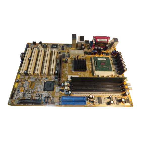
Hardware Installation Chapter 2 - Hardware Installation 2.1 System Board Layout... -
Page 17: System Memory
Hardware Installation Warning: Electrostatic discharge (ESD) can damage your system board, proces- sor, disk drives, add-in boards, and other components. Perform the upgrade instruction procedures described at an ESD workstation only. If such a station is not available, you can provide some ESD protection by wearing an antistatic wrist strap and attaching it to a metal part of the system chassis. -
Page 18: Installing The Dim Module
Hardware Installation 2.2.1 Installing the DIM Module A DIM module simply snaps into a DIMM socket on the system board. Pin 1 of the DIM module must correspond with Pin 1 of the socket. Notch Pin 1 1. Pull the “tabs” which are at the ends of the socket to the side. -
Page 19: Cpu
Hardware Installation 2.3 CPU 2.3.1 Overview The system board is equipped with a surface mount Socket A CPU socket. This socket is exclusively designed for installing an AMD CPU. 2.3.2 Installing the CPU 1. Make sure the PC and all other peripheral devices connected to it has been powered down. -
Page 20: Hardware Installation
Hardware Installation 5. Position the CPU above the socket then align the gold mark on the corner of the CPU (designated as pin 1) with pin 1 of the socket. Important: Handle the CPU by its edges and avoid touching the pins. Gold mark Pin 1 6. -
Page 21: Installing The Fan And Heat Sink
Hardware Installation 7. Once the CPU is in place, push down the lever to lock the socket. The lever should click on the side tab to indicate that the CPU is completely secured in the socket. Lever lock 2.3.3 Installing the Fan and Heat Sink The CPU must be kept cool by using a CPU fan with heat sink. - Page 22 Hardware Installation Do not apply the paste if the fan / heat sink already has a patch of thermal paste on its underside. Peel the strip that covers the paste then place the fan / heat sink on top of the CPU.
-
Page 23: Jumper Settings
Hardware Installation 2.4 Jumper Settings 2.4.1 Jumper Settings for Clearing CMOS Data 1-2 On: Normal 2-3 On: (default) Clear CMOS Data If you encounter the following, a) CMOS data becomes corrupted. b) You forgot the keyboard, supervisor or user password. c) You are unable to boot-up the computer system because the proc- essor’s clock was incorrectly set in the BIOS. - Page 24 Hardware Installation 4. After powering-on the system, press <Del> to enter the main menu of the BIOS. 5. Select the Frequency/Voltage Control submenu and press <Enter>. 6. Set the “CPU Clock” field to its default setting or an appropri- ate bus clock. Refer to the Frequency/Voltage Control section in chapter 3 for more information.
-
Page 25: Rear I/O Panel
Hardware Installation 2.5 Rear Panel I/O Ports RJ45 PS/2 Mouse Parallel Line-in USB 2 Line-out Mic-in PS/2 COM 1 COM 2 USB 1 USB 3-4 The rear panel I/O ports consist of the following: • PS/2 mouse port • PS/2 keyboard port •... - Page 26 Hardware Installation 2.5.1 PS/2 Mouse and PS/2 Keyboard Ports " PS/2 Mouse PS/2 Keyboard The system board is equipped with an onboard PS/2 mouse (Green) and PS/2 keyboard (Purple) ports - both at location CN19 of the system board. The PS/2 mouse port uses IRQ12. If a mouse is not connected to this port, the system will reserve IRQ12 for other expansion cards.
-
Page 27: Serial Port
Hardware Installation 2.5.2 Serial Port COM 1 COM 2 The system board is equipped with two onboard serial ports (COM 1: CN22 and COM 2: CN23) - both in Teal/Turquoise color. These ports are RS-232C asynchronous communication ports with 16C550A-compatible UARTs that can be used with modems, serial printers, remote display terminals, and other serial devices. -
Page 28: Parallel Port
Hardware Installation 2.5.3 Parallel Port Parallel The system board has a standard parallel port (Burgundy) at lo- cation CN21 for interfacing your PC to a parallel printer. It sup- ports SPP, ECP and EPP. Setting Function Allows normal speed operation (Standard Parallel Port) but in one direction only. -
Page 29: Universal Serial Bus Ports
Hardware Installation 2.5.4 Universal Serial Bus Ports USB 2 USB 1 USB 4 USB 3 USB 5-6 USB 7-8 Four onboard USB 2.0/1.1 ports (Black) are at locations CN24 (USB 1-2) and CN26 (USB 3-4) of the system board. J9 (USB 5-6) and J10 (USB 7-8) connectors allow you to con- nect 4 additional USB 2.0/1.1 ports. - Page 30 Hardware Installation Wake-On-USB The Wake-On-USB function allows you to use a USB device to wake up the system. • BIOS Setting: Enable the USB wake up function in the Power Management Setup submenu (“IRQ/Event Activity Detect” section) of the Award BIOS. Important: •...
- Page 31 Hardware Installation 2.5.5 RJ45 Fast-Ethernet Port RJ45 LAN The system board is equipped with an onboard RJ45 fast- ethernet LAN port at location CN26 of the system board. It al- lows the system board to connect to a local area network by means of a network hub.
- Page 32 Hardware Installation 2.5.6 Audio Line-in Line-out Mic-in Surr_con Front audio " Mic-in, Line-in and Line-out The mic-in, line-in and line-out jacks are at location CN25 of the system board. A jack is a one-hole connecting interface for insert- ing a plug. •...
- Page 33 Hardware Installation Front Audio The front audio connector (J18) allows you to connect to the line-out and mic-in jacks that are at the front panel of your sys- tem. Using this connector will disable the rear audio’s line-out and mic-in functions. Remove the jumper caps from pins 5-6 and pins 9-10 of J18 prior to connecting the front audio cable connector.
-
Page 34: I/O Connectors
Hardware Installation 2.6 I/O Connectors 2.6.1 Internal Audio Connectors Ground Ground Ground Ground Left audio Right audio Left audio Right audio channel channel channel channel " CD-in AUX-in The CD-in (J15) and AUX-in (J14) connectors are used to re- ceive audio from a CD-ROM drive, TV tuner or MPEG card. - Page 35 Hardware Installation 2.6.2 S/PDIF Connector SPDIF out SPDIF in " The S/PDIF connector (J16) is used to connect external S/PDIF ports. Connect the audio cable connector to J16. Make sure pin 1 of the audio cable connector is aligned with pin 1 of J16.
-
Page 36: Floppy Disk Drive Connector
Hardware Installation 2.6.3 Floppy Disk Drive Connector The system board is equipped with a shrouded floppy disk drive connector that supports two standard floppy disk drives. To pre- vent improper floppy cable installation, the shrouded floppy disk header has a keying mechanism. The 34-pin connector on the floppy cable can be placed into the header only if pin 1 of the connector is aligned with pin 1 of the header. -
Page 37: Serial Ata Connectors
Hardware Installation 2.6.4 Serial ATA Connectors SATA 2 SATA 1 Connect one end of the SATA cable to J6 (SATA 1) or J8 (SATA 2) and the other end to your serial ATA device. BIOS Setting Enable the onboard SATA in the Integrated Peripherals submenu (“VIA OnChip IDE Device”... -
Page 38: Ide Disk Drive Connectors
Hardware Installation 2.6.5 IDE Disk Drive Connectors IDE-P IDE-S IDE-P IDE-S The system board is equipped with two shrouded PCI IDE head- ers that will interface four Enhanced IDE (Integrated Drive Elec- tronics) disk drives. To prevent improper IDE cable installation, each shrouded PCI IDE header has a keying mechanism. - Page 39 Hardware Installation Note: Refer to your disk drive user’s manual for information about selecting proper drive switch settings. Adding a Second IDE Disk Drive When using two IDE drives, one must be set as the master and the other as the slave. Follow the instructions provided by the drive manufacturer for setting the jumpers and/or switches on the drives.
-
Page 40: Cooling Fan Connectors
Hardware Installation 2.6.6 Cooling Fan Connectors Power Ground Sense CPU fan Ground Sense Power System fan Connect the CPU fan’s cable connector to the CPU fan connec- tor (J3) on the system board. The system fan connector (J4) is used to connect an additional cooling fan. The cooling fans will provide adequate airflow throughout the chassis to prevent over- heating the CPU and system board components. - Page 41 Hardware Installation 2.6.7 DIMM Standby Power LED DIMM Standby Power LED The DIMM Standby Power LED will turn red when the system’s power is on or when it is in the Suspend state (Power On Sus- pend or Suspend to RAM). It will not light when the system is in the Soft-Off state.
-
Page 42: Power Connector
Hardware Installation 2.6.8 Power Connector +12V 5VSB PW-OK Ground Ground Ground Ground Ground PS-ON Ground Ground -12V 3.3V 3.3V 3.3V We recommend that you use a power supply that complies with the ATX12V Power Supply Design Guide Version 1.1. An ATX12V power supply has a standard 20-pin ATX main power connector that must be inserted onto the CN18 connector. -
Page 43: Front Panel Connectors
Hardware Installation 2.6.9 Front Panel Connectors ATX-SW PWR-LED HD-LED SPEAKER RESET HD-LED: Primary/Secondary IDE LED This LED will light when the hard drive is being accessed. RESET: Reset Switch This switch allows you to reboot without having to power off the system thus prolonging the life of the power supply or sys- tem. - Page 44 Hardware Installation PWR-LED: Power/Standby LED When the system’s power is on, this LED will light. When the system is in the S1 (POS - Power On Suspend) or S3 (STR - Suspend To RAM) state, it will blink every second. Note: If a system did not boot-up and the Power/Standby LED did not light after it was powered-on, it may indicate that the CPU...
-
Page 45: Chapter 3 - Bios Setup
BIOS Setup Chapter 3 - BIOS Setup 3.1 Award BIOS Setup Utility The Basic Input/Output System (BIOS) is a program that takes care of the basic level of communication between the processor and peripherals. In addition, the BIOS also contains codes for vari- ous advanced features found in this system board. -
Page 46: Bios Setup
BIOS Setup 3.1.1 Standard CMOS Features Use the arrow keys to highlight “Standard CMOS Features” and press <Enter>. A screen similar to the one below will appear. The settings on the screen are for reference only. Your version may not be identical to this one. - Page 47 BIOS Setup 3.1.1.3 IDE Primary Master, IDE Primary Slave, IDE Secondary Master and IDE Secondary Slave Move the cursor to the “IDE Primary Master”, “IDE Primary Slave”, “IDE Secondary Master” or “IDE Secondary Slave” field, then press <Enter>. The following screen will appear. The settings on the screen are for reference only.
- Page 48 BIOS Setup Capacity Displays the approximate capacity of the disk drive. Usually the size is slightly greater than the size of a formatted disk given by a disk checking program. Cylinder This field displays the number of cylinders. Head This field displays the number of read/write heads. Precomp This field displays the number of cylinders at which to change the write timing.
- Page 49 BIOS Setup 3.1.1.5 Video This field selects the type of video adapter used for the primary system monitor. Although secondary monitors are supported, you do not have to select the type. The default setting is EGA/VGA. EGA/VGA Enhanced Graphics Adapter/Video Graphics Array. For EGA, VGA, SVGA and PGA monitor adapters.
- Page 50 BIOS Setup 3.1.1.8 Extended Memory Displays the amount of extended memory detected during boot- 3.1.1.9 Total Memory Displays the total memory available in the system.
-
Page 51: Advanced Bios Features
BIOS Setup 3.1.2 Advanced BIOS Features The Advanced BIOS Features allows you to configure your sys- tem for basic operation. Some entries are defaults required by the system board, while others, if enabled, will improve the per- formance of your system or let you set some features according to your preference. - Page 52 BIOS Setup 3.1.2.2 CPU Internal Cache and External Cache These fields speed up the memory access. The default is Enabled, which provides better performance by enabling cache. 3.1.2.3 CPU L2 Cache ECC Checking The processors supported by the system board come with built- in Level 2 cache.
- Page 53 BIOS Setup 3.1.2.7 Swap Floppy Drive When this field is enabled and the system is booting from the floppy drive, the system will boot from drive B instead of drive A. When this field is disabled and the system is booting from the floppy drive, the system will boot from drive A.
- Page 54 BIOS Setup 3.1.2.11 Typematic Rate Setting Disabled Continually holding down a key on your keyboard will cause the BIOS to report that the key is down. Enabled The BIOS will not only report that the key is down, but will first wait for a moment, and, if the key is still down, it will begin to report that the key has been depressed repeatedly.
- Page 55 BIOS Setup 3.1.2.16 OS Select for DRAM > 64MB Select the “OS2” option only if the system that is running an OS/2 operating system has greater than 64MB RAM. 3.1.2.17 HDD S.M.A.R.T. Capability The system board supports SMART (Self-Monitoring, Analysis and Reporting Technology) hard drives.
-
Page 56: Advanced Chipset Features
BIOS Setup 3.1.3 Advanced Chipset Features The settings on the screen are for reference only. Your version may not be identical to this one. This section gives you functions to configure the system based on the specific features of the chipset. The chipset manages bus speeds and access to system memory resources. - Page 57 BIOS Setup 3.1.3.1 DRAM Clock/Drive Control Move the cursor to this field and press <Enter>. The following screen will appear. The settings on the screen are for reference only. Your version may not be identical to this one. Current FSB Frequency This field will show the detected FSB of the CPU.
- Page 58 BIOS Setup 200 MHz memory clock speed will run at 400MHz DDR. DRAM Timing This field is used to select the timing of the DRAM. By SPD The EEPROM on a DIMM has SPD (Serial Pres- ence Detect) data structure that stores informa- tion about the module such as the memory type, memory size, memory speed, etc.
- Page 59 BIOS Setup Tras Non-DDR400/DDR400 The options are 5T/6T, 8T/12T, 6T/8T and 7T/10T. Active to CMD (Trcd) The options are 2T, 3T, 4T and 5T. DRAM Burst Length The options are 4 and 8. DRAM Command Rate The options are 1T Command and 2T Command. Write Recovery Time The options are 2T and 3T.
- Page 60 BIOS Setup 3.1.3.2 AGP & P2P Bridge Control Move the cursor to this field and press <Enter>. The following screen will appear. The settings on the screen are for reference only. Your version may not be identical to this one. AGP Aperture Size This field is relevant to the memory-mapped graphics data of the AGP card installed in your system.
- Page 61 BIOS Setup AGP Fast Write Select Enabled to support the AGP Fast Write function. AGP Master 1 WS Write Set this field to Enabled to add one clock tick to AGP write operations. AGP Master 1 WS Read Set this field to Enabled to add one clock tick to AGP read op- erations.
- Page 62 BIOS Setup 3.1.3.6 PCI Delay Transaction When enabled, this function frees up the PCI bus for other PCI masters during the PCI-to-ISA transactions. This allows PCI and ISA buses to be used more efficiently and prevents degradation of performance on the PCI bus when ISA accesses are made. 3.1.3.7 Memory Hole This field is used to select the memory area that must not be addressed to the ISA bus.
-
Page 63: Integrated Peripherals
BIOS Setup 3.1.4 Integrated Peripherals The settings on the screen are for reference only. Your version may not be identical to this one. 3.1.4.1 VIA OnChip IDE Device Move the cursor to this field and press <Enter>. The following screen will appear. The settings on the screen are for reference only. - Page 64 BIOS Setup OnChip SATA This field is used to enable or disable the onboard SATA. OnChip IDE Channel0 and OnChip IDE Channel1 These fields allow you to enable or disable the primary and sec- ondary IDE controller. The default is Enabled. Select Disabled if you want to add a different hard drive controller.
- Page 65 BIOS Setup IDE HDD Block Mode Enabled The IDE HDD uses the block mode. The system BIOS will check the hard disk drive for the maximum block size the system can transfer. The block size will depend on the type of hard disk drive. Disabled The IDE HDD uses the standard mode.
- Page 66 BIOS Setup Onboard LAN Boot ROM Enable this field if you wish to use the boot ROM (instead of a disk drive) to boot-up the system and access the local area net- work directly. If you wish to change the boot ROM’s settings, type the <Shift> and <F10>...
- Page 67 BIOS Setup 3.1.4.3 Super IO Device Move the cursor to this field and press <Enter>. The following screen will appear. The settings on the screen are for reference only. Your version may not be identical to this one. Onboard FDC Controller Enabled Enables the onboard floppy disk controller.
- Page 68 BIOS Setup Parallel Port Mode The options are SPP, EPP, ECP and ECP+EPP. These apply to a standard specification and will depend on the type and speed of your device. Refer to your peripheral’s manual for the best op- tion. Allows normal speed operation but in one direction only.
-
Page 69: Power Management Setup
BIOS Setup 3.1.5 Power Management Setup The Power Management Setup allows you to configure your sys- tem to most effectively save energy. The settings on the screen are for reference only. Your version may not be identical to this one. 3.1.5.1 ACPI Function This function should be enabled only in operating systems that ®... - Page 70 BIOS Setup 3.1.5.3 Power Management Option This field allows you to select the type (or degree) of power saving by changing the length of idle time that elapses before the “HDD Power Down” field is activated. Min Saving Minimum power saving time for the “HDD Power Down”...
- Page 71 BIOS Setup 3.1.5.7 Video Off Method This determines the manner in which the monitor is blanked. V/H SYNC + Blank This selection will cause the system to turn off the vertical and horizontal syn- chronization ports and write blanks to the video buffer.
- Page 72 BIOS Setup 3.1.5.10 AC Lost Auto Restart Keep Off When power returns after an AC power failure, the system’s power is off. You must press the Power button to power-on the system. Turn On When power returns after an AC power failure, the system will automatically power-on.
- Page 73 BIOS Setup PS2KB Wakeup Select This field allows you to use a function key or password to wake up the system. Hot Key Use any of the function keys, between F1 and F12, to wake up the system. Password Use a password to wake up the system. Select this option and press <Enter>.
- Page 74 BIOS Setup PCI Master When set to On, the system will respond and wake up to any PCI or bus master activity. PowerOn by PCI Card Enabled This field should be set to Enabled only if your PCI card such as LAN card or modem card uses the PCI PME (Power Management Event) signal to re- motely wake up the system.
- Page 75 BIOS Setup Resume Time (hh:mm:ss) This is used to set the time you would like the system to power- on. If you want the system to power-on everyday as set in the “Date (of Month)” field, the time set in this field must be later than the time of the RTC set in the Standard CMOS Features submenu.
- Page 76 BIOS Setup 3.1.6 PnP/PCI Configurations This section describes configuring the PCI bus system. It covers some very technical items and it is strongly recommended that only experienced users should make any changes to the default settings. The settings on the screen are for reference only. Your version may not be identical to this one.
- Page 77 BIOS Setup 3.1.6.3 IRQ Resources Move the cursor to this field and press <Enter>. This field is used to set each system interrupt to either Reserved or PCI Device. The settings on the screen are for reference only. Your version may not be identical to this one.
-
Page 78: Pc Health Status
BIOS Setup 3.1.7 PC Health Status The settings on the screen are for reference only. Your version may not be identical to this one. 3.1.7.1 Shutdown Temperature You can prevent the system from overheating by selecting a tem- perature in this field. If the system detected that its temperature exceeded the one set in this field, it will automatically shutdown. - Page 79 BIOS Setup 3.1.8 Frequency/Voltage Control The settings on the screen are for reference only. Your version may not be identical to this one. 3.1.8.1 Auto Detect DIMM/PCI Clk When enabled, the system will automatically send clock signals to existing DIMM or PCI devices. 3.1.8.2 Spread Spectrum Leave this field in its default setting.
- Page 80 BIOS Setup 3.1.8.4 CPU Voltage Control This field allows you to manually adjust to a higher core voltage that is supplied to the CPU. If you want to use the CPU’s default core voltage, leave this field in its default setting. The CPU’s Vcore will be generated according to the CPU VID configuration.
- Page 81 BIOS Setup 3.1.9 Load Fail-Safe Defaults The “Load Fail-Safe Defaults” option loads the troubleshooting default values permanently stored in the ROM chips. These set- tings are not optimal and turn off all high performance features. You should use these values only if you have hardware problems. Highlight this option in the main menu and press <Enter>.
-
Page 82: Load Optimized Defaults
BIOS Setup 3.1.10 Load Optimized Defaults The “Load Optimized Defaults” option loads optimized settings from the BIOS ROM. Use the default values as standard values for your system. Highlight this option in the main menu and press <Enter>. Type <Y> and press <Enter> to load the Setup default values. -
Page 83: Set Supervisor Password
BIOS Setup 3.1.11 Set Supervisor Password If you want to protect your system and setup from unauthorized entry, set a supervisor’s password with the “System” option se- lected in the Advanced BIOS Features. If you want to protect access to setup only, but not your system, set a supervisor’s pass- word with the “Setup”... -
Page 84: Set User Password
BIOS Setup 3.1.12 Set User Password If you want another user to have access only to your system but not to setup, set a user’s password with the “System” option se- lected in the Advanced BIOS Features. If you want a user to en- ter a password when trying to access setup, set a user’s password with the “Setup”... - Page 85 BIOS Setup 3.1.13 Save & Exit Setup When all the changes have been made, highlight “Save & Exit Setup” and press <Enter>. Type “Y” and press <Enter>. The modifications you have made will be written into the CMOS memory, and the system will reboot.
-
Page 86: Via Raid Bios
BIOS Setup 3.1.14 Exit Without Saving When you do not want to save the changes you have made, highlight “Exit Without Saving” and press <Enter>. Type “Y” and press <Enter>. The system will reboot and you will once again see the initial diagnostics on the screen. If you wish to make any changes to the setup, press <Ctrl>... -
Page 87: Updating The Bios
3.3 Updating the BIOS To update the BIOS, you will need the new BIOS file and a flash utility, AWDFLASH.EXE. You can download them from DFI’s web site or contact technical support or your sales representative. 1. Save the new BIOS file along with the flash utility AWDFLASH.EXE to a floppy disk. - Page 88 BIOS Setup 6. The following will appear. Do You Want to Save BIOS (Y/N) This question refers to the current existing BIOS in your sys- tem. We recommend that you save the current BIOS and its flash utility; just in case you need to reinstall the BIOS. To save the current BIOS, press <Y>...
-
Page 89: Chapter 4 - Supported Softwares
Supported Software Chapter 4 - Supported Software 4.1 Desktop Management Interface (DMI) The system board comes with a DMI built into the BIOS. DMI, along with the appropriately networked software, is designed to make inventory, maintenance and troubleshooting of computer sys- tems easier. -
Page 90: Using The Dmi Utility
Supported Software 4.1.2 Using the DMI Utility Award DMI Configuration Utility Copyright Award Software Inc, 1996 [Edit DMI] [Add DMI] [Load DMI File] [Save DMI File] BIOS *** BIOS Auto Detect *** System Enclosure/Chassis Type : BIOS Information Processor Handle : 0000 Memory Controller Vendor Name : Memory Module... -
Page 91: Supported Software
Supported Software Add DMI 1. Use the ← or → arrow keys to select the Add DMI menu. 2. Highlight the item on the left screen that you would like to add by using the ↑ or ↓ arrow keys, then press <Enter>. 3. -
Page 92: Drivers And Utilities Installation Notes
Supported Software 4.2 Drivers, Utilities and Software Applications The CD that came with the system board contains drivers, utili- ties and software applications required to enhance the perform- ance of the system board. Inser t the CD into a CD-ROM drive. The autorun screen (Mainboard Utility CD) will appear. - Page 93 Supported Software ® 4.2.1 VIA Service Pack ® The VIA Service Pack contains the following drivers. • VIA ATAPI Vendor Support Driver • AGP VxD Driver • IRQ Routing Miniport Driver • VIA INF Driver To install VIA Service Pack, please follow the steps below. 1.
- Page 94 Supported Software ® Service Pack Installation Notes The “AGP VxD Driver” and “VIA INF Driver” drivers in the “VIA ® ® Service Pack” are supported in Windows 95, Windows 98, Win- ® ® ® dows 98 SE, Windows ME and Windows 2000.
-
Page 95: Audio Drivers
Supported Software 4.2.2 Audio Drivers The audio drivers are supported in the following operating sys- tems: Windows 98 SE, Windows ME, Windows 2000 and Windows To install the driver, please follow the steps below. 1. On the left side of the autorun screen, click the “AUDIO” icon. - Page 96 Supported Software 3. Click “Install Device Driver”. The following screen will appear. 4. Follow the prompts on the screen to complete installation. 5. Reboot the system for the driver to take effect. Note: The 3D Audio Configuration software, which is an audio panel for setting basic audio configurations, will at the same time be installed into your system.
- Page 97 Supported Software 4.2.3 USB 2.0 Drivers To install the USB 2.0 driver, please follow the steps below. 1. On the left side of the autorun screen, click the “USB” icon. 2. Click “USB 2.0 Drivers” on the main screen. The following screen will appear.
- Page 98 Supported Software 4.2.4 VIA LAN Drivers The LAN drivers for Windows 98, Windows 98 SE, Windows ME, Windows 2000 and Windows XP support “Autorun”. To install the LAN driver, please follow the steps below. 1. On the left side of the autorun screen, click the “NETWORK” icon.
- Page 99 Supported Software 4.2.5 SATA RAID Drivers If the SATA drives will be configured as RAID, you must install the SATA RAID Drivers. 1. On the left side of the autorun screen, click the “TOOLS” icon. 2. Click “SATA RAID Drivers” on the main screen. The following screen will appear.
- Page 100 Supported Software The SATA drivers are contained in the CD that came with the system board. Prepare a blank formatted diskette then copy all the SATA driver files from the SATA\DRIVERDISK\SATA directory of the CD into the blank diskette. You can now use the diskette to install the drivers.
- Page 101 Supported Software 4.2.6 Microsoft DirectX 8.1 To install, please follow the steps below. 1. On the left side of the autorun screen, click the “TOOLS” icon. 2. Click “Microsoft DirectX 8.1” on the main screen. The screen below will appear. 3.
-
Page 102: Audio Configuration
Supported Software 4.3 3D Audio Configuration When you install the audio driver, the 3D Audio Configuration software will at the same time be installed into your system. 3D Audio Configuration is an audio panel for setting basic audio con- figurations. It allows you to configure 2-channel, 4-channel and 6- channel audio modes as well as configure the audio effects. - Page 103 Supported Software Speaker Output When you open 3D Au- dio Configuration, the de- fault screen that appears is the Speaker Output. This where will configure analog output settings to speakers. S/PDIF This panel is used to configure S/PDIF output which provides a low-dis- tortion digital data transfer between audio devices.
-
Page 104: Installation Notes
2. All steps or procedures to install software drivers are subject to change without notice as the softwares are occassionally updated. Please go to DFI's web site at "http://www.dfi.com/ support1/download2.asp" for the latest version of the drivers or software applications. -
Page 105: Appendix A - Using The Suspend To Ram Function
Using the Suspend to RAM Function Appendix A - Using the Suspend to RAM Function A.1 Using the Suspend to RAM Function ® ® ® ® ® If you are using the Windows 98 operating system, please follow the steps below. Select “Power Management Setup”... - Page 106 Using the Suspend to RAM Function ® ® ® ® ® ® ® ® ® ® Boot Windows 98. In the Windows 98 desktop, click the Start button. Move the cursor to Settings, then click Control Panel. To check whether ACPI was properly installed, double-click the System icon.
- Page 107 Using the Suspend to RAM Function Click File System. In the “Typical role of this computer” field, select “Mobile or docking system”. Click Apply, then click OK. Restart the computer. 10. Repeat step 7 to open the Control Panel dialog box. Double- click the Power Management icon.
- Page 108 Using the Suspend to RAM Function 12. After completing the steps above and you want to power-off the computer, you do not need to go through the process of closing files, applications and operating system. You can power- off the computer at once by pressing the power button or ®...
-
Page 109: Appendix B - System Error Messages
System Error Message Appendix B - System Error Message When the BIOS encounters an error that requires the user to cor- rect something, either a beep code will sound or a message will be displayed in a box in the middle of the screen and the message, PRESS F1 TO CONTINUE, CTRL-ALT-ESC or DEL TO ENTER SETUP, will be shown in the information box at the bottom. - Page 110 System Error Message Hard Disk(s) fail (80) HDD reset failed. Hard Disk(s) fail (40) HDD controller diagnostics failed. Hard Disk(s) fail (20) HDD initialization error. Hard Disk(s) fail (10) Unable to recalibrate fixed disk. Hard Disk(s) fail (08) Sector Verify failed. Keyboard is locked out - Unlock the key The BIOS detects that the keyboard is locked.
-
Page 111: Appendix C - Troubleshooting
Troubleshooting Appendix C - Troubleshooting C.1 Troubleshooting Checklist This chapter of the manual is designed to help you with problems that you may encounter with your personal computer. To efficiently troubleshoot your system, treat each problem individually. This is to ensure an accurate diagnosis of the problem in case a problem has multiple causes. -
Page 112: Power Supply
Troubleshooting The picture seems to be constantly moving. 1. The monitor has lost its vertical sync. Adjust the monitor’s verti- cal sync. 2. Move away any objects, such as another monitor or fan, that may be creating a magnetic field around the display. 3. -
Page 113: Hard Drive
Troubleshooting Hard Drive Hard disk failure. 1. Make sure the correct drive type for the hard disk drive has been entered in the BIOS. 2. If the system is configured with two hard drives, make sure the bootable (first) hard drive is configured as Master and the sec- ond hard drive is configured as Slave. -
Page 114: System Board
Troubleshooting 3. Verify that the attached serial device works by attaching it to a serial port that is working and configured correctly. If the serial device does not work, either the cable or the serial device has a problem. If the serial device works, the problem may be due to the onboard I/O or the address setting. - Page 115 Troubleshooting...
Need help?
Do you have a question about the KT600-AL and is the answer not in the manual?
Questions and answers