Table of Contents
Advertisement
Direct Vent Gas Fireplace
Installation and Operating Manual
Viewpoint Series
MODEL: VP-36M Modern Vortex Burner
D O N O T D I S C A R D
Installer:
Leave this manual with the appliance.
Consumer: Retain this manual for future reference.
IMPORTANT: This appliance is only for use with
the type(s) of gas indicated on the rating plate.
An LP conversion kit is available when using Liquid
Propane gas; order separately.
This appliance may be installed in an aftermarket
permanently
located,
home, where not prohibited by local codes. A
manufactured home (USA only) or mobile home OEM
installation must conform with the Manufactured
Home Construction and Safety Standard, Title 24
CFR, Part 3280, or when such a standard is not
applicable, the Standard for Manufactured Home
Installations, ANSI/NCSBCS A225.1, or Standard
for Gas Equipped Recreational Vehicles and Mobile
Housing, CSA Z240.4
manufactured
(mobile)
www.stellarhearth.com
WARNING: If the information in these instructions
are not followed exactly, a fire or explosion may
result causing property damage, personal injury
or loss of life.
Do not store or use gasoline or other
—
flammable vapors and liquids in the vicinity
of this or any other appliance.
— WHAT TO DO IF YOU SMELL GAS
•
Do not try to light any appliance.
•
Do not touch any electrical switch; do
not use any phone in your building.
•
Immediately call your gas supplier from
a neighbor's phone. Follow the gas
supplier's instructions.
•
If you cannot reach your gas supplier,
call the fire department.
— Installation and service must be performed
by a qualified installer, service agency or
the gas supplier.
These products have been tested and listed for use in
the USA and Canada by:
Underwriters Laboratories,
Northbrook, IL
File #MH48906
Page 1
Advertisement
Table of Contents
Troubleshooting

Related Manuals for Stellar Hearth VP-36M


Summary of Contents for Stellar Hearth VP-36M
- Page 1 Direct Vent Gas Fireplace Installation and Operating Manual Viewpoint Series MODEL: VP-36M Modern Vortex Burner D O N O T D I S C A R D Installer: Leave this manual with the appliance. Consumer: Retain this manual for future reference.
-
Page 2: Listing Label Information & Homeowner Reference 2
Installers, please leave manual for the homeowner to use for future reference. Please have the fireplace model information available when contacting a dealer or Stellar Hearth for additional information and service work. The model information regarding your fireplace can be found on the rating plate located in the valve control area underneath the burner assembly of the fireplace. -
Page 3: Table Of Contents
VP-36M TABLE OF CONTENTS Venting 24-31 Listing Label Information & Homeowner Reference A. Approved Venting 5" x 8" M&G Dura-Vent DVA, Metal-Fab and Safety Information BDM Pro-Form, Direct Vent Systems B. Horizontal Vent System Clearances Commonwealth of Massachusetts Requirements C. Horizontal Termination 24" Section... - Page 4 VP-36M TABLE OF CONTENTS Remote Control Operating Instructions 37-42 Troubleshooting 51-52 A. Remote Control Icon Identification A. Main Control Module Will Not Work B. Remote Control Information B. Pilot Will Not Light/Stay Lit C. Continuous Pilot - Cold Conditions C. Pilot Flame Always On/Will Not Extinguish D.
-
Page 5: Safety Information
Do not operate this appliance with the glass/frame assembly removed, cracked or broken. The glass assembly, part # STL-611-011 shall only be replaced as a complete unit, as supplied by Stellar Hearth Products. Replacement of the glass assembly must only be performed by a licensed or qualified service person. DO NOT SUBSTITUTE MATERIALS. -
Page 6: Commonwealth Of Massachusetts Requirements
2 - COMMONWEALTH OF MASSACHUSETTS REQUIREMENTS IMPORTANT NOTE The following requirements reference various Massachusetts and national codes not contained in this manual. For all sidewall horizontally vented gas fueled equipment installed in every dwelling, building or structure used in whole or in part for residential purposes, including those owned or operated by the Commonwealth and where the side wall exhaust vent termination is less than (7) feet above finished grade in the area of the venting, including but not limited to decks and porches, the following requirements shall be satisfied: INSTALLATION OF CARBON MONOXIDE DETECTORS... -
Page 7: Specifications
3 - SPECIFICATIONS A. FIREPLACE DIMENSIONS LETTER KEY Glass Front to Floor to Vent Stand-off Opening DESCRIPTION Height Width Frame Back Width Depth Vent Center Center Height Width Height (Vertical) (Horizontal) INCHES 35-3/8 44-1/2 27-1/2 40-1/2 8-3/4 14-3/4 43-3/8 DIMENSIONS 1130 1029 1101... -
Page 8: B. Clearances
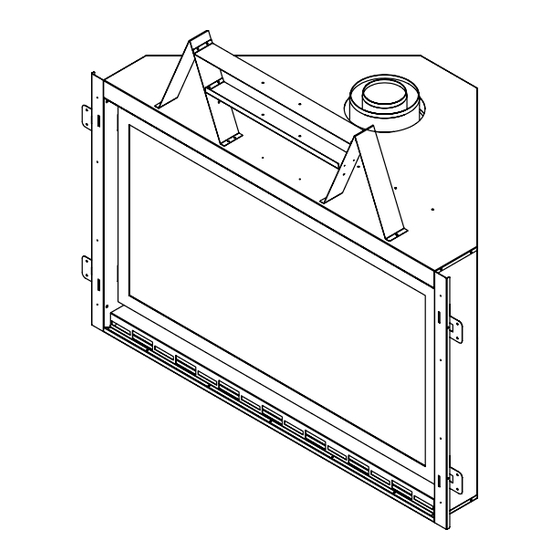
3 - SPECIFICATIONS FIRE WARNING Top stand-off bracket must be attached to fireplace. Do not remove. Stand-off brackets are not load-bearing. Non-combustible zone: Stand-offs provide 12” (305 mm) minimum clearance to header. Use only non-combustible material in this area for entire width of fireplace. Do not use wood, sheetrock, etc., in this zone. -
Page 9: C. Installation Overview
3 - SPECIFICATIONS IMPORTANT NOTE The qualified installer should follow the procedure best suited for the installation. C. INSTALLATION OVERVIEW Frame an opening for fireplace, allowing for vent installation and type of installation (corner, flat wall, type of front to be used and/or clean face application). -
Page 10: Specifications
3 - SPECIFICATIONS E. CLEAN TRIM FRONT AND HEARTH Keep the outer dimensions of the decorative front and hearth specifications in consideration, up front, when planning the framing and finishing of the fireplace. See Section 13 - Finishing. CLEAN TRIM FRONT ◄... -
Page 11: Prepare The Fireplace
4 - PREPARE THE FIREPLACE FIRE WARNING STAND-OFFS PROVIDE 12” (305 mm) MINIMUM CLEARANCE TO HEADER. USE ONLY NON-COMBUSTIBLE MATERIAL IN THIS AREA FOR ENTIRE WIDTH OF FIREPLACE. DO NOT USE WOOD, SHEETROCK, ETC., IN THIS ZONE. IMPORTANT NOTE TOP STAND-OFF BRACKETS MUST BE FORMED AND ATTACHED PRIOR TO POSITIONING FIRE PLACE INTO FRAMED OPENING. -
Page 12: Framing
5 - FRAMING A. WALL ENCLOSURE ROUGH OPENING IMPORTANT NOTE Framing dimensions should allow for wall covering thickness and fireplace facing materials. When using a hearth, adjust rough opening size as necessary to maintain at least minimum clearance requirements. B. MINIMUM FINISHED OPENING DIMENSIONS IMPORTANT WARNING Provide adequate clearance in front of fireplace to operate lower grille, open and close optional decorative doors / full door faces, access components, installation of gas line, fan, etc. -
Page 13: C. Horizontal Termination
5 - FRAMING Determine exact position of your fireplace, including hearth height, width, and depth. If possible, place fireplace in such a manner that vent termination will be placed between two studs, eliminating the need for additional framing. If masonry is to be used (optional), prepare the necessary foundation for the masonry load. When masonry construction is being used, a lintel must be used over top of fireplace to support the added weight. -
Page 14: D. Vertical Termination
5 - FRAMING D. VERTICAL TERMINATION Follow vent pipe manufacturer’s installation instructions using approved direct vent pipe for vertical terminations. A minimum 1” (25 mm) clearance on all sides of vertical vent pipe must be maintained. IMPORTANT NOTE A venting firestop must be used on all horizontal vent runs. Follow instructions in Section 12 - Venting, Figure 12F. IMPORTANT COLD AIR NOTE Cold air transfer area. -
Page 15: Framing
5 - FRAMING F. NAILING FLANGE ASSEMBLY & INSTALLATION IMPORTANT CAUTION NEVER PERMANENTLY REMOVE THESE ASSEMBLIES FROM FIREPLACE . THEY MUST BE SECURED IN PLACE REGARDLESS OF FINISH MATERIAL USED. Locate the nailing tabs (4) in the manual bag. Place the first tab into the slot on the fireplace wrap. Place the forward bent tab behind the edge of the wrap and install with one sheetmetal screw. -
Page 16: Mantel Requirements
6 - MANTEL REQUIREMENTS A. NON-COMBUSTIBLE ZONE Non-Combustible Zone: No materials allowed on top of the fireplace within shaded area for entire width and depth of fireplace. This air space MUST remain open. Mantel (304.8 mm) 47” x 15-1/2” 8” 15”... -
Page 17: A. Remove Glass Frame Assembly
7 - GLASS FRAME ASSEMBLY MAKE SURE AND REVIEW THE WARNINGS REGARDING GLASS REMOVAL AND INSTALLATION ON PAGE 16. A. REMOVE GLASS FRAME ASSEMBLY If decorative front is already in place, remove the front or mesh screen. CLEAN TRIM FRONT: Remove the front by lifting and unhooking the front. Locate spring-loaded handles securing glass frame assembly at top &... - Page 18 8 - STL-FK160 FAN KIT INSTALLATION (OPTIONAL) INSTALLATION OF THIS FAN SHOULD BE DONE ONLY BE A QUALIFIED INSTALLER. IMPORTANT ELECTRICAL WARNING MAKE SURE HOUSEHOLD BREAKER IS SHUT OFF PRIOR TO WORKING ON ANY ELECTRICAL LINES. IMPORTANT ELECTRICAL WARNING THIS APPLIANCE IS EQUIPPED WITH A THREE-PRONG (GROUNDING) PLUG FOR PROTECTION AGAINST SHOCK HAZARD AND SHOULD BE PLUGGED DIRECTLY INTO A PROPERLY GROUNDED THREE-PRONG RECEPTACLE.
- Page 19 8 - STL-FK160 FAN KIT INSTALLATION (OPTIONAL) Remove decorative front, glass assembly and lower vanity panel for access to the base of the fireplace. GAS LINE MUST BE DISCONNECTED TO INSTALL BLOWER. If not disconnected, disconnect the gas line, then proceed. Locate left and right side blowers.
- Page 20 8 - STL-FK160 FAN KIT INSTALLATION (OPTIONAL) Move the module assembly. (It is held in place by velcro strips.) Place the right side blower to the right and behind the support left. Figure 8.3 Figure 8.3 Plug the blower into the extension module. Figure 8.4 Figure 8.4 INS_VP3M_Rev J...
- Page 21 8 - STL-FK160 FAN KIT INSTALLATION (OPTIONAL) Route the blower wires behind valve from right blower to left blower and connect the wires to terminals on the left blower. Figure 8.5 Place both blowers 1/4” from the fireplace walls. Figure 8.5 Plug extension module into the electrical junction box.
-
Page 22: Thermostat Remote Control Installation
9 - THERMOSTAT REMOTE CONTROL INSTALLATION A remote control comes standard with the Viewpoint Series Fireplaces and are factory installed. Refer to Section 17 - Remote Control Operating Instructions. 10 - GAS LINE CONNECTION A. GAS CONVERSION This fireplace is manufactured for use with Natural Gas. An LP conversion kit is available. LPCK-VP36M is sold separately. Follow instructions found in Section 24 - LPCK-VP36M Conversion Kit Instructions, or included with conversion kit. -
Page 23: Gas Line Specifications
11 - GAS LINE SPECIFICATIONS A. GAS LINE CONNECTION NATURAL GAS LP GAS 5.0 inches W.C. 11.0 inches W.C. MINIMUM INLET GAS PRESSURE (7.0 W.C. recommended) (recommended) MAXIMUM INLET GAS PRESSURE 10.5 inches W.C 13.0 inches W.C. MANIFOLD PRESSURE (HI) 3.5 inches W.C 10.0 inches W.C. -
Page 24: Venting
12 - VENTING IMPORTANT NOTE Consult the local and national installation codes to assure adequate combustion and ventilation air is available. IMPORTANT NOTE Flame height and appearance will vary depending upon venting configuration and type of fuel used. Venting requirements apply to both Natural and LP gas. -
Page 25: F. Wall Pass-Through
F. WALL PASS-THROUGH IMPORTANT NOTE DURAVENT 58DVA-WT WITH HEAT SHIELD OR DURAVENT VERTICAL 58DVA-FS WALL PASS-THRU (OR METAL-FAB/BDM EQUIVALENT) MUST BE USED ON ALL HORIZONTAL VENT TERMINATIONS. THIS INCLUDES BOTH INTERIOR AND EXTERIOR WALLS. FOLLOW INSTRUCTIONS BELOW. A = 10-1/2" (268mm) B = 10-1/2"... -
Page 26: G. Horizontal Terminations
12 - VENTING G. HORIZONTAL TERMINATIONS IMPORTANT NOTE Horizontal sections require 1/4” (6 mm) rise for every 12” (305 mm) of travel. IMPORTANT NOTE Section 21 - Finalizing the Installation has information on restrictor installation in conjunction with venting installation (F. Restrictor Troubleshooting) and information on restrictor recommendations depending on burner flame appearance and instructions on installation after venting is completed (G. -
Page 27: I. Vertical Vent System Clearances
12 - VENTING I. VERTICAL VENT SYSTEM CLEARANCES ALL APPROVED VENTING BOTTOM SIDES VERTICAL 1 inch (25mm) 1 inch (25mm) 1 inch (25mm) J. VERTICAL TERMINATIONS MINIMUM: 10 ft. (3.05 m) + termination cap. MAXIMUM: 40 ft. (9.14 m) + termination cap. K. - Page 28 12 - VENTING L. HORIZONTAL & VERTICAL COMBINATION TERMINATIONS MAXIMUM: 10 ft. (3.05 m) vertical + 20 ft. (6.10 m) horizontal + cap. Measurements are from the center lines on the pipe to the back of the termination cap plate. Figure 12L INS_VP3M_Rev J Page 28...
- Page 29 M. HORIZONTAL TERMINATION VENT CAP LOCATION & CLEARANCES This gas appliance must not be connected to a chimney serving any other appliance. • Terminations against vinyl siding must use a vinyl siding protector. Follow instructions included. • DO NOT RECESS TERMINATION KIT INTO OUTSIDE BUILDING MATERIALS - i.e.: brick, stone, siding, etc. If necessary, extend framing so that termination kit will be exposed once building materials are installed.
- Page 30 12 - VENTING M. HORIZONTAL TERMINATION VENT CAP LOCATION & CLEARANCES Inside Corner Outside Corner Recessed Location A = Combustible 9” (229mm) F= Combustible 6” (152mm) = Non-combustible 2” (51mm) = Non-combustible 6” (152mm) Balcony Balcony with perpendicular side wall with no side wall C = Clearance from corner in recessed location...
-
Page 31: Venting
12 - VENTING N. VERTICAL VENT CAP LOCATION AND CLEARANCES ROOF PITCH H (Min.) Ft. H (Min.) M FLAT TO 6/12 1.0* 0.30 OVER 6/12 TO 7/12 1.25* 0.38 OVER 7/12 TO 8/12 1.5* 0.46 OVER 8/12 TO 9/12 2.0* 0.61 OVER 9/12 TO 10/12 2.5*... -
Page 32: Finishing
13 - FINISHING A. FINISHING THE WALL IMPORTANT NOTE DO NOT COVER THE NON-COMBUSTIBLE BOARD WITH COMBUSTIBLE FINISHING MATERIAL 47” x 15-1/2” (1193.8mm x 393.7mm) Non-combustible board (shipped with fireplace) MUST be used. Combustible wall covering up to the side of the fireplace. Do not overlap the black fireplace face. -
Page 33: A..2 Brick Or Ledgestone Liner
Replace the screw with the clip underneath it to the hold the Clips glass in place. DO NOT OVER-TIGHTEN! Repeat on the left side. Re-install the grate. Figure 14A.1 A.2 BRICK OR LEDGESTONE LINER KIT - Not an available option for the VP-36M INS _VP36M _Rev J Page 33... - Page 34 The VP-36M ships with the Vortex burner, glass top and glass media dam in-place protected Glass Top by packaging. Vortex Burner Glass Media Dam Figure 14B.1 The VP-36M requires two 20 lbs. bags of glass media that is shipped separately. Figure 14B.2 INS_VP3M_Rev J Page 34...
-
Page 35: Valve & Pilot Assembly Components
15 - VALVE & PILOT ASSEMBLY COMPONENTS A. VALVE WIRING SCHEMATIC Figure 15A INS _VP36M _Rev J Page 35... -
Page 36: Valve & Pilot Assembly Components
15 - VALVE & PILOT ASSEMBLY COMPONENTS C. IPI GAS VALVE B. IPI PILOT ASSEMBLY OUTLET PRESSURE TAP (MANIFOLD PRESSURE) “PILOT WIRE CONNECTION” LOW LIMIT SCREW (LLS) ALUMINUM CAP INLET PRESSURE TAP NG/LP PLUNGER UNDERNEATH PILOT ADJUSTMENT SCREW “MAIN” WIRE CONNECTION Figure 15B Figure 15C 16 - CONTROL MODULE COMPONENTS... -
Page 37: B. Remote Control Information
17 - REMOTE CONTROL OPERATION INSTRUCTIONS A. REMOTE ICON IDENTIFICATION Remote: Skytech Premium Transmitter Model AF-4000TSS02 comes standard with the fireplace. Touch Screen LCD Takes four (4) AAA batteries (included) MODE Zone SET TEMP Zone ROOM TEMP Zone TIME/PROG Zone FLAME Zone LIGHT Zone FAN Zone... -
Page 38: D. Operation Using Battery Power
17 - REMOTE CONTROL OPERATION C. CONTINUOUS PILOT - FOR VERY COLD CONDITIONS The IPI gas control system has the option of a continuous (standing) pilot feature. This allows you to change from a spark-to-pilot system to a stand- ing pilot system during cold weather conditions. By having the pilot on continuously, the firebox will remain warm and a draft is established in the vent, allowing the main burner to turn on with less air-flow disruption. -
Page 39: F. Initial Set-Up
17 - REMOTE CONTROL OPERATION F. INITIAL SET-UP Plug Extension Module and AC Adaptor into receptacles. Install (4) AA batteries into battery compartment of Backup Battery Pack , making sure batteries are installed in proper direction. Position between valve and front of stove. A Velcro strip has been attached to help secure in place. The Hand Held Remote operates on (4) AAA batteries. -
Page 40: L. Manual Mode
17 - REMOTE RECEIVER INFORMATION L. MANUAL MODE This remote can be manually or thermostatically operated. Press MODE/SET button for manual ON. The flame icon will appear on the LCD screen. Press MODE/SET button again to put the control into THERMO mode. - Page 41 17 - REMOTE RECEIVER INFORMATION O. FLAME MODE This remote will operate the flame, allowing for (6) different flame height levels. Press the MODE/SET button. The FLAME icon will appear on the LCD screen. Press the FLAME icon on then screen, then press UP or DOWN buttons to select desired flame level.
-
Page 42: R. System Operation Without Handheld Remote
17 - REMOTE RECEIVER INFORMATION Q. SET THE DAY AND TIME DISPLAY The current day of the week and time of day will be continuously displayed in the TIME/PROG Zone (except during SET UP operations). The day of the week will be displayed as one of the following: S, M, T, W, T, F, S. The Time of day will be in 12-hour AM, 12-hour PM format with midnight being displayed as 12:00 am. -
Page 43: Lighting & Shutdown
18 - LIGHTING & SHUTDOWN FOR YOUR SAFETY - READ BEFORE LIGHTING IMPORTANT WARNING IF YOU DO NOT FOLLOW THESE INSTRUCTIONS EXACTLY, A FIRE OR EXPLOSION MAY RESULT, CAUSING PROPERTY DAMAGE, PERSONAL INJURY OR LOSS OF LIFE. DUE TO HIGH SURFACE TEMPERATURES, KEEP CHILDREN, CLOTHING AND FURNITURE AWAY. This appliance needs fresh air for safe operation and must be installed so there are provisions for adequate combustion and ventilation air. -
Page 44: Lighting & Shutdown
18 - LIGHTING & SHUTDOWN A. LIGHTING STOP! Read safety information on previous page and front cover of this manual before continuing IMPORTANT NOTE This fireplace is equipped with an ignition device which automatically lights the pilot. DO NOT try to light the pilot by hand. -
Page 45: Pressure Testing
19 - PRESSURE TESTING IMPORTANT NOTE When operating fireplace in this capacity, the only function available is burner operation on HI. IMPORTANT NOTE The appliance and its individual shutoff valve must be disconnected from the gas supply piping system during any pressure testing of that system at pressures in excess of ½... -
Page 46: Error Codes
20 - ERROR CODES A. IGNITION SAFETY: Protection for Ignition System Error Code: One beep every one second. Description of Fault: Warns users if pilot is not successfully ignited in 60 seconds. How to Clear: Press MODE button to OFF then to ON to re-attempt ignition. What to Check: •... -
Page 47: Finalizing The Installation
21 - FINALIZING THE INSTALLATION A. FLAME APPEARANCE Flame appearance is affected by several factors including altitude, venting configuration and fuel quality. Although the venturi setting has been factory set, adjustments may be necessary for optimal performance and visual aesthetics. When fireplace is first lit, the flames will be blue. -
Page 48: Finalizing The Installation
21 - FINALIZING THE INSTALLATION E. RESTRICTOR USAGE • Turn fireplace on and allow to burn for 15 minutes. • If flames indicate there is excessive draft (flickering, short flames), a restrictor may be necessary. • If flames indicate insufficient draft (lifting or ghosting flames), a previously installed restrictor may need to be modified or removed. IMPORTANT WARNING TO AVOID PROPERTY DAMAGE OR PERSONAL INJURY, ALLOW FIREPLACE AMPLE TIME TO COOL BEFORE MAKING ANY ADJUSTMENTS AND / OR INSTALLATIONS... -
Page 49: Maintenance
Do not operate this fireplace with glass/frame assembly removed, cracked or broken. • • The glass assembly, part #STL-611-011, shall only be replaced as a complete unit, as supplied by Stellar Hearth Products. • Replacement of glass & frame assembly, must only be performed by a licensed or qualified service person. -
Page 50: Maintenance
You will see three sets of twin wires going to the light brackets on through Stellar Hearth. the underside of the firebox. One is immediately behind a small BRAND: Sunlite silver panel above the gas valve itself. -
Page 51: Troubleshooting
23 - TROUBLESHOOTING A. MAIN CONTROL MODULE WILL NOT LEARN TRANSMITTER • Ensure REMOTE/OFF switch on side of main control module is set to REMOTE. • Make sure batteries in both the hand held remote and backup battery pack are installed in the proper direction and are not drained. •... -
Page 52: Troubleshooting
23 - TROUBLESHOOTING E. MAIN FLAME WILL NOT LIGHT • Verify gas supply is turned on. • Ensure pilot flame will ignite. If not, see pilot flame troubleshooting on previous page. Make sure white cap leads marked “MAIN” from module are securely connected to terminals marked “MAIN” on valve body. •... -
Page 53: Replacement Parts
24 - REPLACEMENT PARTS - VP-36M Description EXTENDED DESCRIPTION PART NUMBER PILOT ASSEMBLY - NG STL-199 GAS VALVE - NG AMERICAN FLAME STL-010-501 BURNER ORIFICE -NG STL-012-030 LOW SET SCREW - NG STL-LSS-00 PILOT ORIFICE - NG NG-PILOT-OR FLEXIBLE GAS LINE 90^ 1/8 NPT 18”... -
Page 54: Limited Lifetime Warranty
Limited Lifetime Warranty Stellar Hearth Products, a brand of Big Woods Hearth Products Inc, warrants the following components for life to the original owner, subject to proof of purchase: Firebox, Heat Exchanger, Combustion Chamber, Grate and Stainless Steel Burners. Electrical components and wearable parts (gas valve, blowers, wiring, switches, remote controls, gasketing, and pilot assembly) are covered and will be provided free of charge for a period of one year from date of purchase.
Need help?
Do you have a question about the VP-36M and is the answer not in the manual?
Questions and answers