Sign In
Upload
Manuals
Brands
dixell Manuals
Temperature Controller
iCHILL IC208CX
dixell iCHILL IC208CX Manuals
Manuals and User Guides for dixell iCHILL IC208CX. We have
3
dixell iCHILL IC208CX manuals available for free PDF download: User Manual, Quick Reference Manual
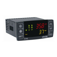
dixell iCHILL IC208CX User Manual (115 pages)
Brand:
dixell
| Category:
Temperature Controller
| Size: 15 MB
Table of Contents
Index
2
General Advice
7
Safety Precautions
7
General Features
9
Main Function
9
Compressor Start up
9
Chiller Management
9
Weekly ON/OFF
10
Dynamic Setpoint
10
Change over
10
Remote off
10
Ic200 CX Table of the Features
11
User Interface
12
Display Configuration
12
IC 206Cx / IC 208Cx
12
Remote Keyboard
12
Main Display (Upper Display)
13
To Force the Display Read-Out
14
Icons Meaning
15
Meaning/Functioning of the Bottom Display LED
16
Display Layout
16
How to Read the Measurement List
16
Read Probe Values of Circuit
16
Display Information
17
Modify the Set Point
17
Display Visualization in Remote off
17
Display Visualization in Std-By
18
Display in Condensing Unit
18
Key Function
19
Key Combinantion
19
Remote Terminal
20
First Installing
20
On Board Clock
20
RTC Setup
20
Analog and Digital Output Configuration
21
Analog Input
21
Analog Input Configuration
21
Digital Output Configuration
22
Analog Output Configuration
23
Programming with the “Hot Key 64”
24
Programming Using the Keyboard
24
Password Default Values
24
How to Change a Parameter Value
24
Change the Password Value
25
Enter the Programming Level
25
Visibility and Parameter Value Locked
27
Digital Input and Output Polarity
27
Function Menu “ M” Key
28
Change the Polarity of the Digital Input-Outputs
28
Alarm List
28
Compressor Overload Alarm Reset
28
Compressor Overload Password
29
Alarm Log List
29
Erase the Alarm Log List
29
Password Value of the Alarm List
29
Reset the Running Hour
30
Reset the Starts-Up Number
30
Chiller / Heat Pump Selection
32
Graph: Automatic Change over
32
Operation Mode Selection by Keyboard
32
Operation Mode Selection by Probe
32
Unit Start - Stop
33
Start-Stop and Stand-By from Keyboard
33
Unit Start
33
Motocondensing Unit Start
33
Compressor Thermoregulation
34
Mode with Digital Input Configurated as Heat Pump Request
34
Thermoregulation Parameter Description
34
Thermoregulation: Proportional or Neutral Zone
35
Graph of the Compressor
35
Compressor Status into the Neutral Zone
36
Compressor Regulation in Heat Pump
36
Management of Compressors Inverter Controlled
37
Unit in Chiller
37
Compressor Activation
37
Thermoregulation and Compressors Rotation
40
Saturation - Circuit Balancing
40
Compressors Start-Up
40
Circuit Saturation
40
Part Winding
41
Capacity Control
41
Part Winding Start-Up
41
Step Control Process
41
Minimum Load Start-Up
42
Direct Action with Sequential Step
42
Inverse Action with Sequential Step
42
Thermoregulation of the Compressors with Different Size
43
Example with Screw Compressor
43
Pump down
43
Pump down with Dedicated Pressure Switch
44
Pump down Function with Dedicated Pressure Probe
44
Pump down Alarm During Compressors Star-Up
45
Pump down Alarm During Compressors Switching off
45
Pump down by Delay Time
45
Unloading
46
High Temperature of the Evaporator Water Inlet
46
Unloading Description
46
Unloading Information
46
Solenoid Valve for Liquid Injection
47
Water Pump of the Evaporator / Supply Fan
47
Regulation in Heat Pump Mode
47
Low Temperature of the Evaporator Water Outlet
47
Evaporator Pump Group
48
Hot Start Only for Air/Air Unit in Heat Pump Mode
48
Supply Fan Operation with Digital Input and RTC
48
Evaporator Water Pump Rotation
48
Water Pump of the Condenser
49
Pump Group of the Condenser
49
Condenser Water Pump Control
49
Condenser Water Pump Rotation
49
Modulating Operation of the Pumps
50
Condenser Water Pump Rotation through Digital Input Control
50
Modulating Control Type 1
50
Modulating Control on Compressor Demand
50
Condenser Fan Regulation
51
Modulating Control of the Condenser Pump in Chiller Mode
51
Modulating Control of the Condenser Pump in Heat Pump Mode
51
On/Off Condenser Fan
52
Proportional Fan Control
52
Condensing Unit
52
Proportional Regulation of Condenser Fans
53
Regulation of the Condenser Fan in Chiller Mode
53
On/Off Regulation of the Condenser Fan in Heat Pump Mode
53
Thermoregulation of the Anti Freeze
54
Integration Heating or Boiler
54
Boiler Heater Relays
55
Boiler Function
55
Integration Control Ar11=1
55
Heating Control Ar11=2
55
Defrost Cycle
56
Forced Defrost
56
Combined Defrost
56
Manual Defrost
56
Automatic Defrost
57
Other Information about the Defrost
58
Defrost by Condenser Fan
58
End Defrost by Low Water Outlet Evaporator Temperature
58
Defrost Parameter Description
58
Energy Saving
60
Digital Input Activation
60
Energy Saving Time Table with RTC
60
Example of a Daily Programming
61
Enater Parameter Programming
61
Weekly Programming
61
Activation with Rtc Programming and Digital Input
61
Dynamic Setpoint Graph
62
NTC Probe with Positive Differential
62
NTC Probe with Negative Differential
62
Geothermal Function
63
Regulation Probes
63
Function Deactivation
63
Auxiliary Function
64
Auxiliary Function on Relay Output
64
Auxiliary Relay on Direct Action
64
Auxiliary Function on Analog Outputs
65
Auxiliary Relay on Reverse Action
65
Load Maintenance
66
Load Maintenance Resquests
66
Messages - Alarm Codes
67
Ap1 - Ap2 - Ap3 - Ap4 - Ap5 - Ap6 - Ap7 - Ap8 Probe Failure
67
Evaporator Flow Alarm
67
Condenser Flow Alarm
67
Overload Alarm of the Supply Fan
68
Eprom Alarm
68
Power Supply Frequency Alarm
69
Generic Alarm with Stop Regulation
69
Generic Signal Alarm
69
Configuration Alarm of the Unit
70
Compressor Inverter Controlled
71
Compressor with Different Weight Capacity
71
Geothermal Function / Alarm Differential Inlet_Outlet
71
ARTF Clock Failure
72
ARTC Clock Alarm
72
Unloading from High Temperature of the Evaporator Water Inlet
72
Alarm from High Temperature of the Evaporator Water Inlet
72
Low Air Ambient Temperature
73
Evaporator Pumps
74
Condenser Pumps Maintenance Request
74
High Pressure Switch Circuit
74
Compressor High Pressure Alarms
77
C2 OP Pressure Switch Alarm
77
Oil Alarm from Pressure Switch or Oil Level Switch
77
Compressor Overload Alarm
78
Defrost Alarm
78
Automatic to Manual Alarm Procedure
80
Alarm Relay and Buzzer
80
Keyboard Alarm
80
Number of Events Per Hour
80
Table of the Output Status in Alarm Condition
81
Type and Status of the Loads in Case of Alarm
82
Table of the Parameters
84
Thermoregulation Probe Selection in Chiller
84
Thermoregulation Probe Selection in Heat Pump
84
Display Read-Out of the Remote Keyboards
85
Configuration
85
Probe Offset
86
Digital Inputs
86
Relay Outputs
86
Proportional Output
86
OUT 4 Configuration
87
OUT 5 Configuration
87
OUT 6 Configuration
87
Terminale Remoto
87
Partialization (Capacity Control)
89
Compressor Start-Up
89
Evaporator Water Pump / Supply Fan
89
Compressor Liquid Injection
91
Load Management in Neutral Zone
91
Pump down to Time
91
Tandem Function
91
Modulating Condenser Water Pump
92
Auxiliary Relay
92
Auxiliary Relay of the Circuit 1
92
Auxiliary Relay Circuit 2
92
Auxiliary Proportional Output N° 2
93
Condenser Fan
93
Fan in Chiller Mode
94
Fan in Heat Pump Mode
94
Boiler Function in Chiller Mode
96
Boiler Function in Heat Pump
96
Water Pumps on off or STD-BY
96
Defrost
96
Defrost Operative Mode
97
Start / Stop Defrost from Analog Input
97
Defrost with Condenser Fan
97
Low Alarm
97
High Alarm
98
Oil Alarm
98
Pump down Alarm
98
Anti-Freeze Alarm in Heat Pump Mode
99
Compressor High Discharge Temperature
99
Generic Alarm / Signal 2
100
Reset High Pressure / Temperature Alarm
100
High Water Evaporator Inlet Temperature
100
Low Water Evaporator Inlet Temperature
100
Black-Out
102
Wiring Connections
102
Hardware Resources
102
Analog Input for Pressure Ratiometric Transducer
105
Pwm Output for Condensing Fan Speed Control
106
Proportional Outputs Configured for Aux Relay Control
107
Hot Key 64 Connection
107
Installing and Mounting
109
Panel Cut out
109
Vertical Boards
110
Electrical Connections
111
Accessories
111
Monophase Fan Control
111
Power Supply
111
Wiring Kit
112
Transformer
112
Technical Data
113
Advertisement
dixell iCHILL IC208CX Quick Reference Manual (58 pages)
iCHiLL
Brand:
dixell
| Category:
Temperature Controller
| Size: 3 MB
Table of Contents
Table of Contents
2
Electrical Connections
5
Installing and Mounting
5
Technical Data
5
Wiring Connections
5
1 General Advice
7
2 Ic200 CX Table of the Features
8
3 User Interface
9
Display Configuration
9
4 Display Layout
11
How to Read the Measurement List
11
5 Display Information
12
Modify the Set Point
12
Read Probe Values of Circuit 1 or 2
13
Key Function
13
Key Combinantion
14
6 Remote Terminal
14
7 First Installing
15
On Board Clock (Optional)
15
RTC Setup
15
8 Analog and Digital Output Configuration
16
Analog Input Pb1 - Pb2 - Pb5 - Pb6
16
Analog Input Configuration Pb3 - Pb4
16
Digital Output (Relay) Configuration RL1- RL8
18
Analog Output Configuration 0 ÷ 10 Volt (OUT1 E OUT2)
19
Out4)
19
9 Programming with the "Hot Key 64
19
10 Programming Using the Keyboard
20
Password Default Values
20
Enter the Pr1 - Pr2 - Pr3 Programming Levels
20
How to Change a Parameter Value
21
Change the Password Value
21
Enter the Programming Level Pr1
22
Enter the Programming Level Pr2
22
Enter the Programming Level Pr3
22
11 Function Menu “ M” Key
24
Function Menu " M" Key
24
Alarm List: Show and Reset
24
Compressor Overload Alarm Reset
25
Compressor Overload Password
25
Alarm Log List
25
Erase the Alarm Log List
26
Password Value of the Alarm List
26
Disable - Enable a Single Circuit
26
12 Table of the Output Status in Alarm Condition
27
ALARM: "A" Type and Status of the Loads in Case of Alarm
27
ALARM: "B" Type and Status of the Loads in Case of Alarm
29
ALARM: "C" Type and Status of the Loads in Case of Alarm
30
13 Table of the Parameters
31
Bar Dec
44
725 Psi Int
44
Dec
44
Int Bar Dec Psi Int
44
Dec Int
45
Bar Dec
45
0= Not Enabled
47
Dec
47
Bar Dec 725 Psi Int
48
Dec Int
48
Bar Dec 203 Psi Int
49
14 Black-Out
54
Wiring Connections
55
Installing and Mounting
56
Panel Cut- out
56
Electrical Connections
57
Technical Data
58
dixell iCHILL IC208CX Quick Reference Manual (40 pages)
Brand:
dixell
| Category:
Temperature Controller
| Size: 1 MB
Table of Contents
Table of Contents
3
1 General Warning
5
Please Read before Using this Manual
5
Safety Precautions
5
Product Disposal (Weee)
6
2 Using the Quick Reference Guide
6
3 Ic200 CX Table of the Features
7
4 User Interface
8
Meaning of the Leds
8
Display and Icons
8
5 Display Layout
9
6 Other Display Information
10
Read the Set Point Value
10
Modify the Set Point
10
7 Key Function
11
Key Combinantion
12
8 First Installing
12
On Board Clock (Optional)
12
Rtc Setup
12
9 Parameters Programming with the "Hot Key 64
13
How to Program an Instrument with an Already Programmed "Hot Key
13
(Download)
13
How to Copy the Parameter Map into the "Hot Key" (Upload)
13
10 Programming Using Local User Interface
13
Enter the Programming Level Pr1
13
Enter the Programming Level Pr2
14
Enter the Programming Level Pr3
14
11 Menu ( Menu Key)
14
Alarm List: Read and Reset
15
Alarm Log List
15
12 Remote Keyboard Vicx620 Evo
16
13 Remote Keyboard V2I820
16
Probes Visualization
18
Visualizzazione / Modifica Set Point
18
Alarm Visualization
19
14 Table of the Output Status in Alarm Condition
20
Alarm: "A" Type and Status of the Loads in Case of Alarm
20
Alarm: "B" Type and Status of the Loads in Case of Alarm
22
Alarm: "C" Type and Status of the Loads in Case of Alarm
23
Warning
24
15 Black-Out
24
16 Wiring Connections
24
Ic206Cx Connections
24
208Cx Connections
25
Remote Keyboard Connection
26
Analog Inputs Ntc - Ptc Probes
28
Digital Inputs
29
Analog Input for Pressure Transducer Pp30 (4 ÷ 20Ma Signal)
30
Pwm Output for Condensing Fan Speed Control
32
Proportional Output for Fan Condensing Control or for Compressor Inverter Controlled or for Auxiliary Outputs
33
Proportional Output 0
34
Proportional Outputs Configured for Aux Relay Control
36
17 Installing and Mounting
37
Panel Cut- out
37
Vertical Boards Vi620Cx Panel Cut-Out
37
V2I820 Panel Cut-Out
38
18 Electrical Connections
38
19 Technical Data
39
Advertisement
Advertisement
Related Products
dixell IC200CX Series
dixell iCHILL IC206CX
dixell IPRO.CHILL IPC115D SSR
dixell IPRO.GENIUS IPG108D
dixell IPRO.GENIUS IPG208D
dixell IPRO.GENIUS IPG108E
dixell IPRO.LINK IPL500D
dixell IPX106D
dixell IPX225D
dixell IPRO.CHILL IPC115D
dixell Categories
Controller
Temperature Controller
Thermostat
Server
Control Unit
More dixell Manuals
Login
Sign In
OR
Sign in with Facebook
Sign in with Google
Upload manual
Upload from disk
Upload from URL