
Related Manuals for Bosch MIC-71xx


Summary of Contents for Bosch MIC-71xx
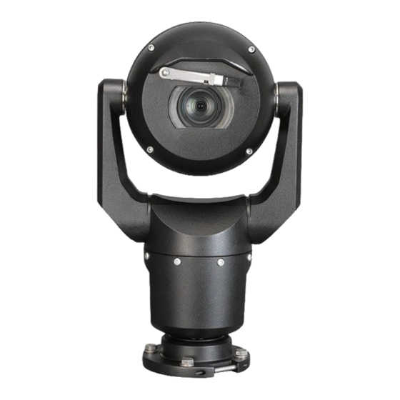
- Page 1 MIC IP starlight 7000 HD, MIC IP dynamic 7000 HD MIC-71xx, MIC-72xx Installation Manual...
-
Page 3: Table Of Contents
Cant the Camera Typical System Configurations 12.1 Typical IP Configuration with 95 W midspan (no I/O connections) 12.2 Typical Configuration with MIC-ALM-WAS-24 12.3 Typical IP Configuration with VJC-7000-90 Troubleshooting Maintenance Technical data Bosch Security Systems Installation Manual 2015.12 | 3.0 | F.01U.291.520... -
Page 4: Safety
200 mm 2.19 100 s 200 mm 0.386 Infrared Hazard Hazard 279 mm Distance Retinal Blue Light 10,000 s 200 mm 22.9 100s 200 mm 0.266 Hazard Hazard 2675 mm Distance 2015.12 | 3.0 | F.01U.291.520 Installation Manual Bosch Security Systems... -
Page 5: Unpacking
Verify that all the parts listed in the Parts List below are included. If any items are missing, notify your Bosch Security Systems Sales or Customer Service Representative. – Do not use this product if any component appears to be damaged. Please contact Bosch Security Systems in the event of damaged goods. –... -
Page 6: Product Description
VG4-A-PSU1, VG4- 24 VAC (96 W) power supply NPD-9501A 95 W midspan A-PSU2 MIC-ALM-WAS-24 Alarm and washer interface MIC-67SUNSHLD Sunshield (white only) accessory unit 2015.12 | 3.0 | F.01U.291.520 Installation Manual Bosch Security Systems... -
Page 7: Overview Of Installation Steps
Install a Install sunshield? sunshield. Will Cant the camera. camera be canted? (Refer to Section 11.) Configure settings. (Refer to Section 13.) Operate the camera. (Refer to Section 16.) Bosch Security Systems Installation Manual 2015.12 | 3.0 | F.01U.291.520... -
Page 8: Configuration Programming In The Shipping Box
“Inverted,” remove the camera from the box and configure it by following the steps in Configuration Programming on a Temporary Table-top Stand, page 9. 4. Disconnect the wires/cables from the connectors in the base of the camera. 2015.12 | 3.0 | F.01U.291.520 Installation Manual Bosch Security Systems... -
Page 9: Configuration Programming On A Temporary Table-Top Stand
(180°). Note that the visor will be near the top of the body of the camera. 6. Disconnect the wires/cables from the connectors in the base of the camera. Bosch Security Systems Installation Manual 2015.12 | 3.0 | F.01U.291.520... -
Page 10: Mounting Location And Mounting Orientation
If the camera is installed in a highly exposed location where lightning strikes may occur, then Bosch recommends installing a separate lightning conductor within 0.5 m (1.6 ft) of the camera and at least 1.5 m (4.9 ft) higher than the camera. A good earth bonding connection to the camera housing itself will provide protection against damage from secondary strikes. -
Page 11: Select The Mounting Orientation
(the body of the MIC), instead of at the bottom of the inverted camera. Note: For canted cameras, ensure that your mounting location provides the necessary clearance (370 mm (14.6 in.)) for the camera head to pan. Bosch Security Systems Installation Manual 2015.12 | 3.0 | F.01U.291.520... - Page 12 Figure 7.1: Top view of canted MIC7000 illustrating distance of pan clearance The figure below illustrates the tilt range of the camera in upright orientation. 90° 90° 55° 55° Figure 7.2: MIC7000 Tilt Range: 145° each direction; 290° if AutoPivot enabled 2015.12 | 3.0 | F.01U.291.520 Installation Manual Bosch Security Systems...
-
Page 13: Overview Of Mounting Options
Overview of Mounting Options | en dynamic 7000 HD Overview of Mounting Options Bosch sells a complete series of mounting brackets that support multiple mounting configurations. The most common type of mounting location is the top of a pole suitable to support CCTV equipment and that provides a robust mounting platform to minimize camera motion and typically has a large base cabinet for mounting ancillary equipment such as power supplies. - Page 14 Other locations for mounting the camera include the top of a building, the side (wall) of a building, the corner of a building, and under the eave of a building. Figure 8.3: Typical Wall mount configuration Figure 8.4: Typical Corner mount configuration 2015.12 | 3.0 | F.01U.291.520 Installation Manual Bosch Security Systems...
- Page 15 Figure 8.6: Direct surface mount – camera inverted (MIC + base gasket + IP67 Weatherization/Connector Kit) Notice! Observe all appropriate safety precautions and local building regulations. Refer to the MIC Series Mounting Brackets Installation Guide for installation instructions. Bosch Security Systems Installation Manual 2015.12 | 3.0 | F.01U.291.520...
-
Page 16: Install The Camera
Electrical Code (NEC)), Canadian Electrical Code, Part I (also called CE Code or CSA C22.1), ® and all applicable local codes. Bosch Security Systems, Inc. accepts no liability for any damages or losses caused by incorrect or improper installation. Caution! -
Page 17: Make Connections - Power And Control
The camera can be powered by a network compliant to High Power-over-Ethernet (Bosch’s version of High PoE) using a Bosch model of High PoE Midspans (sold separately). With this configuration, only a single (Cat5e/Cat6e) cable connection is required to view, to power, and to control the camera. -
Page 18: Ethernet Connections
Use the 95 W midspan sold by Bosch. with illuminators) High PoE (60W only for models Use the 60 W midspan sold by Bosch, or a midspan that is compliant to the without illuminators) IEEE 802.3at, class 4 standard. Terminal Connector RJ45, Male 2015.12 | 3.0 | F.01U.291.520... -
Page 19: Camera Connections
Note: If the MIC camera will be installed directly to a mounting surface, instead of onto a MIC DCA or a MIC wall mount bracket, Bosch recommends using the MIC7000 IP67 Connector Kit (MICIP67-5pk, sold separately) to protect the connections against moisture and dust particles. -
Page 20: Connect The Camera To The Network
Figure 10.2: MIC7000 IP System Configuration 1 MIC7000 camera 2 IP connection 3 Network switch 4 Networking device (computer, DVR/NVR, etc.) 2015.12 | 3.0 | F.01U.291.520 Installation Manual Bosch Security Systems... -
Page 21: Cant The Camera
DCA, with the DCA base upright! It is unstable and might fall and cause bodily injury and/or damage to the camera. Bosch strongly recommends canting the camera after attaching it to a DCA and mounting it in the desired location. - Page 22 ¼ in. drive (item 1, user-supplied) and the supplied spanner tool (item 2). Repeat for the second arm. 1/4” Figure 11.2: Remove yoke caps with spanner tool 2015.12 | 3.0 | F.01U.291.520 Installation Manual Bosch Security Systems...
- Page 23 Carefully support the head of the camera while completing the next four (4) steps. 3. Put the screws in a safe place. You will reinstall the screws at step 6. 4. Repeat steps 2 and 3 for the second yoke arm. Bosch Security Systems Installation Manual 2015.12 | 3.0 | F.01U.291.520...
- Page 24 Do not cant the camera, or let it fall, in the wrong direction! The camera should cant only in the direction indicated in the figure directly below. Figure 11.4: Cant the camera head 2015.12 | 3.0 | F.01U.291.520 Installation Manual Bosch Security Systems...
- Page 25 ≈ 15 N m ≈ 17 N m (≈ 11 ft lb) (≈ 12.5 ft lb) ≈ 15 N m ≈ 17 N m (≈ 11 ft lb) (≈ 12.5 ft lb) Bosch Security Systems Installation Manual 2015.12 | 3.0 | F.01U.291.520...
- Page 26 9. Attach the yoke caps using a torque wrench with ¼ in. drive and the supplied spanner tool. 1/4” 1.4 N m (≈ 12 in. lb) Figure 11.6: Attach yoke caps 10. Canting is complete. 2015.12 | 3.0 | F.01U.291.520 Installation Manual Bosch Security Systems...
-
Page 27: Typical System Configurations
5 Data only IP cable (Cat5e/Cat6e) (user-supplied) between midspan and head-end network Note: The total length of Cat5e/Cat6 cable must be less than 100 m (328 ft) between the camera and the head-end system. Bosch Security Systems Installation Manual 2015.12 | 3.0 | F.01U.291.520... -
Page 28: Typical Configuration With Mic-Alm-Was-24
4 MIC-ALM-WAS-24 enclosure 9 Alarm input / output interface cables (user-supplied) 5 Interface cable for 24 VAC (user- 10 Monitored Normally Open switch for supplied) for MIC-ALM-WAS-24 Supervised Alarm (user-supplied) 2015.12 | 3.0 | F.01U.291.520 Installation Manual Bosch Security Systems... -
Page 29: Typical Ip Configuration With Vjc-7000-90
Cat5e/Cat6e = 100 m max. Figure 12.3: Basic configuration with VIDEOJET connect 7000 1 Ethernet (network) cable (Cat5e/Cat6e) (user-supplied) between a Bosch camera and the port labeled PoE on VIDEOJET connect 7000 2 Data-only IP cable (Cat5e/Cat6e) to the head-end network Note: The cable to the head-end also can be fiber optic cable from one of the two SFP slots. -
Page 30: Troubleshooting
Test your camera with another power supply. intermittently No OSD messages appear. Bosch’s Video SDK is required. Video management software from third parties does not use the SDK. Nothing appears on the screen. Are the power cord and line connection between the camera and monitor made properly? The image on the screen is dim. - Page 31 – Check that the maximum Ethernet cable distance has not been exceeded. If O.K., then: – Restore all camera settings. Background is too bright to see Turn on backlight compensation. subject. Bosch Security Systems Installation Manual 2015.12 | 3.0 | F.01U.291.520...
- Page 32 (especially on the yoke arms). – If there is obvious and severe damage, stop using the camera and contact your Bosch Service Center for assistance. – If no damage is evident, complete one of the following steps: a) Cycle the power on the camera.
-
Page 33: Maintenance
No User-serviceable Parts Except for the external wiper blade, the device contains no user-serviceable parts. Contact your local Bosch service center for device maintenance and repair. In the event of failure, the device should be removed from site for repair. -
Page 34: Technical Data
| Technical data dynamic 7000 HD Technical data For product specifications, see the datasheet for your camera, available on the appropriate product pages of the Online Product Catalog at www.boschsecurity.com. 2015.12 | 3.0 | F.01U.291.520 Installation Manual Bosch Security Systems... - Page 36 Bosch Security Systems, Inc. Bosch Sicherheitssysteme GmbH 1706 Hempstead Road Robert-Bosch-Ring 5 Lancaster, PA, 17601 85630 Grasbrunn Germany www.boschsecurity.com © Bosch Security Systems, Inc., 2015...
Need help?
Do you have a question about the MIC-71xx and is the answer not in the manual?
Questions and answers