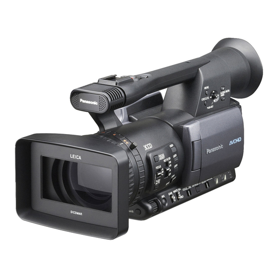
Panasonic AG-HMC150P Operating Instructions Manual
Memory card camera-recorder
Hide thumbs
Also See for AG-HMC150P:
- Operating instructions manual (112 pages) ,
- Parts list (15 pages) ,
- Quick start manual (12 pages)
Table of Contents
Advertisement
Quick Links
This product is eligible for the AVCCAM
3 Year Warranty Repair Program. For
details, see page 5.
Before operating this product, please read the instructions carefully and save this manual
for future use.
SE0808YM5062 -PS
Printed in Japan
Operating Instructions
Memory Card Camera-Recorder
AG-HMC150P
Model No.
ENGLISH
VQT1V33-3
Advertisement
Chapters
Table of Contents

Related Manuals for Panasonic AG-HMC150P


Summary of Contents for Panasonic AG-HMC150P
-
Page 1: Operating Instructions
This product is eligible for the AVCCAM 3 Year Warranty Repair Program. For Operating Instructions details, see page 5. Memory Card Camera-Recorder AG-HMC150P Model No. Before operating this product, please read the instructions carefully and save this manual for future use. ENGLISH... -
Page 2: Read This First
Read this first! indicates safety information. CAUTION: For Battery Pack • Replace only with same or specified type. CAUTION: TO REDUCE THE RISK OF ELECTRIC • Do not disassemble or dispose of in fire. SHOCK, DO NOT REMOVE COVER (OR BACK). NO USER-SERVICEABLE PARTS INSIDE. -
Page 3: Declaration Of Conformity
Model Number: AG-HMC150P Trade Name: Panasonic Responsible Party: Panasonic Corporation of North America One Panasonic Way, Secaucus, NJ 07094 Support contact: 1-800-524-1448 This device complies with Part 15 of the FCC Rules. Operation is subject to the following two conditions: (1) This device may not cause harmful interference, and (2) this device must accept any interference received, including interference that may cause undesired operation. -
Page 4: Important Safety Instructions
1) Read these instructions. 2) Keep these instructions. 3) Heed all warnings. 4) Follow all instructions. 5) Do not use this apparatus near water. 6) Clean only with dry cloth. 7) Do not block any ventilation openings. Install in accordance with the manufacturer’s instructions. 8) Do not install near any heat sources such as radiators, heat registers, stoves, or other apparatus (including amplifiers) that produce heat. - Page 5 Details about user registration and the extended warranty: Please note, this is a site that is not maintained by Panasonic Canada Inc. The Panasonic Canada Inc. privacy policy does not apply and is not applicable in relation to any information submitted. This link is provided to you for convenience.
-
Page 6: Table Of Contents
Contents Read this first! ..........2 Using the zoom function......34 IMPORTANT SAFETY INSTRUCTIONS ..4 Digital zoom function ........34 Outline of operations ........8 Shooting in progressive mode....35 Please read before use ........9 Shooting in manual mode......36 .. - Page 7 Playback Menu Basic playback operations ......59 Using the setup menus ........ 82 Thumbnail screen ......... 60 Using the menus ..........82 Basic thumbnail screen operations ....60 Initializing the menu settings ......83 Setup menu structure ........84 Adding shot marks to clips ......62 Direct shooting functions .........
-
Page 8: Outline Of Operations
Outline of operations This camera-recorder is compatible with the AVCHD standard, and uses low-cost and easily-available SD/SDHC Memory Cards as recording media. The unit enables high-quality picture recording of close to broadcasting standard, as well as highly creative video production. Recording to and Television/Video device/Monitor playback from SD/SDHC... -
Page 9: Please Read Before Use
It is recommended that you use SD Memory Cards or SDHC Memory Cards of SD speed class 2 or above, or the following Panasonic SD Memory Cards (correct as of August 2008). Speed class 4 or above is required for recording in PH mode or HA mode. -
Page 10: Sd Speed Class 4)
Please read before use (continued) This product (SDHC-compatible device) is compatible both with SD Memory Cards and with SDHC Memory Cards. SDHC Memory Cards may be used with SDHC Memory Card-compatible devices, but cannot be used with devices that are only compatible with SD Memory Cards. (Always check the relevant product’s operating instructions when using SDHC Memory Cards with other devices.) SDHC-compatible device... -
Page 11: Precaution For Use
Panasonic makes no guarantees for your recordings. • Please understand that Panasonic makes no guarantees for your recordings in cases where images and/ or sound were not recorded as you intended due to problems with the camera-recorder or SD/SDHC Memory Cards. -
Page 12: About This Manual
The miniSD logo is a trademark. commercial use of a consumer, and no license “AVCHD” and the “AVCHD” logo are trademarks of Panasonic Corporation and Sony Corporation. is granted or shall be implied for any use other This product has been manufactured under than the personal uses detailed below. - Page 13 What is AVCHD? AVCHD is a standard for the recording and playback of highly detailed, high-definition video. Video is compressed in the MPEG-4 AVC/H.264 formats, and audio is recorded in Dolby Digital. Information regarding compatibility of SDHC Memory Cards and recorded video SDHC Memory Cards SDHC Memory Cards cannot be used with non-SDHC-compatible equipment.
-
Page 14: Accessories
Accessories Battery AC Adapter Wireless remote control and battery (CR2025) Eye cup Microphone holder Microphone holder Microphone holder screws adapter Length 6-mm (2) Length 12-mm (2) Component video PIN-BNC conversion Ferrite core (4) Binder (4) cable plugs (3) Shoulder belt CD-ROM The following accessories are attached to the unit. -
Page 15: Description Of Parts
Description of parts Right side and rear side 1 POWER switch (Page 22) 14 Viewfinder (Page 24) 2 START/STOP button (Page 30) 15 SD Memory Card slot cover (Page 30) 3 REC CHECK button (Page 31) 16 SCENE FILE dial (Page 50) 4 Zoom button (Page 34) 17 STAND BY button (Page 23) 5 HANDLE ZOOM switch (Page 34) -
Page 16: Left Side
Description of parts (continued) Left side MENU EXEC PUSH-ENTER AUDIO MON/ADV BARS SHUTTER AUDIO ZEBRA EVF DTL 1 Focus ring (Page 36) 19 AUDIO control knobs (CH1, CH2) (Page 49) 2 Zoom ring (Page 34) 20 LCD monitor (Page 25) If you don’t need the zoom ring pin, fit it into the 21 OPEN button (Page 25) provided pin holder (next page... -
Page 17: Terminals And Mounting Parts
Terminals and mounting parts 9 10 1 Security lock hole 14 CAM REMOTE jack The security cable can be attached here. FOCUS/IRIS (3.5 mm mini jack) For details on the connection, refer to the You can connect a remote control unit (optional) instructions supplied to the cable. -
Page 18: Remote Control
Description of parts (continued) Remote control To use the remote control, set the IR REMOTE item on the OTHER FUNCTIONS menu to ON. The default setting for this item is OFF. (Page 98) 1 EXT. DISPLAY button (Page 70) The following buttons are for functions that 2 DATE/TIME button (Page 70) cannot be executed on this camera-recorder. - Page 19 Battery cannot be recharged when the DC ■ Remaining battery capacity displays cord is connected to the AC adapter. When using Panasonic-manufactured batteries compatible with this product, the remaining battery capacity is displayed in minutes. 90min Time remaining will be displayed after a brief pause.
-
Page 20: Power Sources
Power sources Using the battery Installation Removal Insert the battery until it clicks into place. Set the POWER switch to OFF, and check that the mode lamp is off. Remove the battery while pressing the battery release button. • Support the battery with your hand to ensure that it will not fall. -
Page 21: Adjusting The Hand Strap
Adjusting the hand strap Adjust the hand strap to suit your hand. Open the cover and adjust the length. Close the cover. • Make sure the cover is fully closed. Attaching the shoulder strap Attach the shoulder strap and use it as a precaution against dropping the camera. 20 mm or more 20 mm or more Detaching and attaching the lens hood... -
Page 22: The Remote Control
The remote control Insert the battery Remote control usable range Push the catch in the direction shown by The distance between the remote control and the arrow to remove the holder. unit’s remote control sensor: Within approx. 5 m Angle: Approximately 10° upward, approximately 15°... -
Page 23: Standby Mode
Standby mode ■ Canceling setting Hold down the STAND BY button for at least two seconds while the power is on to cancel the ■ Setting standby mode setting. STD BY will be cease to be Hold down the STAND BY button for at least two displayed on the LCD monitor or the viewfinder. -
Page 24: Viewfinder
Viewfinder This camera has two viewfinders; one is a Fitting the eye cup miniature LCD in the viewfinder and the other is a Attach the eye cup by aligning the projections on retractable 3.5-inch LCD. the eye cup holder and eye cup and fitting them Use the viewfinder that best suits the application together. -
Page 25: Using The Lcd
Using the LCD Emphasizing outlines Set the POWER switch to ON. Emphasizing the outlines of the images you see (Page 22) in the viewfinder or on the LCD makes it easier to focus. Hold down the OPEN button and open the Emphasizing the outlines does not effect the LCD monitor. -
Page 26: Adjusting The Screen Display
Viewfinder (continued) Adjusting the screen display Set the POWER switch to ON. (Page 22) Adjust the selected item by tilting the Operation lever in the directions. Press the MENU button. • For menu operation (Page 82) • Operations may also be performed using buttons on the remote control that correspond to those on the camera. -
Page 27: Changing Backlight Brightness
Changing backlight brightness Reversing image display The brightness of the LCD monitor backlight can Viewing angles and video images can be verified be adjusted between three different settings. by reversing the images displayed on the LCD monitor horizontally or vertically. Select LCD BL in the LCD item on the The recorded images will not be affected if the settings menu SW MODE screen. -
Page 28: Setting The Calendar
Setting the calendar The CLOCK SET value is recorded in the contents (clip), and affects the sequence of playback of the thumbnails. Before carrying out recording, be sure to check and set CLOCK SET and TIME ZONE. This shows you how to adjust the calendar to 17:20 on December 25, 2008. - Page 29 When settings are complete, push the Operation lever, select YES on the confirmation screen, and push the Operation lever again. • The clock can vary in accuracy so check that the time is correct before shooting. • When using the camera overseas, do not set the CLOCK SET option to the local time, but instead enter the time difference from Greenwich mean time according to TIME...
-
Page 30: Shooting
Basic shooting operations Preparing for recording Shooting in auto mode Set the camera’s power switch to OFF. Turn the POWER switch to ON. (Page 22) (Page 22) • Check that the mode lamp (CAM) is lighted • Check that the mode lamp is off. red. -
Page 31: Checking Photos Taken (Rec Check)
• The images shot from when shooting starts until it is stopped are recorded as one clip. CAM mode (PB mode) • When recording is paused after a short period, Illuminated orange: Reading/writing possible a small amount of time may be required after Flashing orange (fast): Verifying card/inspecting pressing the START/STOP button to stop card for possible defects... -
Page 32: Formatting Sd Memory Cards
Basic shooting operations (continued) Formatting SD Memory Cards Set the camera’s power switch to ON. Select YES on the conformation screen. (Page 22) • The SD Memory Card will be formatted. Press the MENU button. Select CARD FUNCTIONS CARD FORMAT from the menu. -
Page 33: Removing Sd Memory Card
Removing SD Memory Card Repairing SD Memory Cards Tilt the viewfinder upwards, and open the SD Memory Card slot cover by sliding it to the left. • Ensure that the SD Memory Card access lamp is not flashing orange before opening the cover. -
Page 34: Using The Zoom Function
Using the zoom function This camera has a 13 x optical zoom function. On the remote control Zoom with the zoom button or the zoom ring. Press ZOOM/VOL buttons to zoom with the motor drive. Zoom button • Zoom speed is fixed at medium. Set the ZOOM switch to SERVO so that you can use the motor-driven zoom. -
Page 35: Shooting In Progressive Mode
Shooting in progressive mode Selecting 1080/30P or 1080/24P in the REC Note the following when shooting in FORMAT option (Page 91) of the setting menu progressive mode. RECORDING SETUP screen enables shooting in • You cannot have a gain of 18 dB. progressive mode. -
Page 36: Shooting In Manual Mode
Shooting in manual mode Set the unit to manual mode when manually The function allocated to the focus ring can adjusting the focus, iris, gain and white balance. be changed with the RING (FOCUS/IRIS) switch. Switching to manual mode FOCUS: Adjust the focus. -
Page 37: Using Focus Assist
Using focus assist Iris adjustments Pressing the FOCUS ASSIST button enlarges the center of the screen or displays a frequency distribution graph in the top right of the screen, enabling the focus to be aligned more easily, and therefore particularly useful when using manual focus. -
Page 38: Adjusting The Gain
Shooting in manual mode (continued) Adjusting the gain Light intensity adjustments When the display is dark, increase the gain to Use the ND FILTER switch to change the ND Filter brighten the display. used (filter to change light intensity). OFF: ND filter is not used. - Page 39 White balance adjustments • White balance cannot be adjusted if the ATW (Auto Tracking White) function is working. Use the AUTO/MANUAL switch to set to • If you have set ON under ATW on the setting manual mode. (Page 36) menu AUTO SW screen, ATW will be selected when auto mode has been established Set the shutter speed.
-
Page 40: Black Balance Adjustments
Shooting in manual mode (continued) Black balance adjustments Auto Tracking White (ATW) In order to reproduce the black accurately, adjust Using the ATW function enables the recording the zero level of all three RGB primary colors. If the environment to be automatically analyzed and an black balance is not adjusted properly, not only will optimum white balance to be constantly maintained the black be reproduced poorly but the color tones... -
Page 41: Shooting Techniques For Different Targets
Shooting techniques for different targets Low angle recording Zebra pattern Recording can be controlled with the handle Press the ZEBRA button in the CAM mode to show START/STOP button during low angle recording by the zebra pattern or marker on the viewfinder and moving the REC selector switch to the ON position. -
Page 42: Marker
Shooting techniques for different targets (continued) Marker PRE REC If you press the ZEBRA button while the zebra Record video and audio from three seconds before pattern is being displayed, a marker appears in the time of the operation to begin recording. the center of the display (if you have set the setup Operation to start Operation to stop... -
Page 43: Optical Image Stabilizer
Optical Image Stabilizer Using the USER buttons Use the Optical Image Stabilizer (OIS) to reduce You can allocate one of eleven features to each of the effects of camera shake when shooting by the three USER buttons. hand. Use these buttons to change shooting settings Press the OIS button to turn the function on and quickly or add effects to the images you are off. -
Page 44: Wave Form Monitor Function
Shooting techniques for different targets (continued) Wave form monitor function Adjusting the volume while shooting An image wave form can be displayed on the LCD Adjusting the volume monitor by pressing the WFM button while in CAM mode. AUDIO MON/ADV AUDIO MON/ADV Press the button again to return to the normal display. -
Page 45: Shot Mark Function
Shot mark function Time stamp function The marks attached to the thumbnails of clips The date and time of recording can be recorded to are called shot marks. On the thumbnail screen video images. monitor you can select only those clips with a Select ON in the TIME STAMP item on the settings shot mark and display them or play them back. -
Page 46: Adjusting The Shutter Speed
Adjusting the shutter speed SHUTTER button SPEED SELECT buttons BARS SHUTTER AUDIO ZEBRA EVF DTL • The current shutter speed appears on the viewfinder and LCD monitor unless you have Press the SHUTTER button. selected OFF in OTHER DISPLAY in the Each time you press the SHUTTER button, the DISPLAY SETUP screen of the setup menus. -
Page 47: Synchro Scan
Synchro scan Set the shutter speed of the synchro scan (used when shooting a television or computer monitor) in the setup menus, SCENE FILE screen, SYNCRO SCAN. (Page 86) • Adjust the shutter speed to match the frequency of the television or computer monitor to minimize the horizontal noise that appears when shooting such subjects. -
Page 48: Switching Audio Input
Switching Audio Input During shooting, you can record up to two Using the built-in microphone channels of sound. You can also switch the input sound to be recorded on each of the channels to Switch the CH1 SELECT switch to INT (L). the built-in microphones, external microphones or •... -
Page 49: Adjusting The Recording Level
CH2 SELECT to INPUT 2. SETUP screen of the setting menu. • Check the recording volume level prior to shooting. • The recording level of this camera is set approximately 8 dB higher than Panasonic broadcasting camera recorders (AJ series products). -
Page 50: Using Scene Files
Using scene files The settings according to the variety of shooting Changing scene file settings circumstances are stored in each position of SCENE FILE dial. The setting value of the scene file can be changed. When shooting, you can retrieve the necessary file Also you can save the changed scene file to each instantly using SCENE FILE dial. - Page 51 Set a 6-character filename with the Operation lever when the following screen is displayed. Set the same as user information. (Page 58) • Characters that can be set Space, A to Z, 0 to 9, : ; < = > ? @ [ ] ^_-./ If the RESET/TC SET button is pressed when the filename has been set, the characters are cleared.
- Page 52 Push the Operation lever again, select YES when the following screen is displayed, and push the Operation lever. • In the case of the scene files, the current settings • In the following example, TITLE001 is the are automatically saved in the unit, and the filename.
-
Page 53: Clip Metadata
Clip metadata You can add the video and audio systems, name SCENARIO: of the videographer, shooting location, text memos This indicates the PROGRAM NAME, SCENE and other information to the video data you have NO. and TAKE NO. recorded on the SD Memory Card. This data is NEWS 1: called the clip metadata. -
Page 54: Uploading The Metadata (Meta Data)
Clip metadata (continued) · Up to 10 items of metadata on the SD Uploading the metadata (META DATA) Memory Card can be displayed, starting from the most recent date of production. You can perform any of the following operations. · If characters other than single-byte If necessary, make preparations prior to alphanumeric characters are used in the... -
Page 55: Using The Counter
The COUNT value is indicated as a four-digit number. The COUNT value is incremented each time a new clip is captured if clip metadata has been read in and TYPE2 has been selected as the recording method. The COUNT value can be reset using the following procedure. -
Page 56: Charging The Built-In Battery/Setting The Time Code
Charging the built-in battery/Setting the time code Recharging the built-in battery Specifying the time code (TC PRESET) The camera’s internal battery saves the date and time. Set TC PRESET so you can record a value of your When LOW INTERNAL BATTERY (indicating that choice as the initial setting for the time code to be the internal battery has no remaining charge) is used at the start of recording. - Page 57 With this unit, the time code value is adjusted in When the screen below appears, set the accordance with the format and frame rate. For time code value. this reason, bear in mind that making a change in Tilt the Operation lever in the directions the format or frame rate may result in discontinuity and select time code value.
-
Page 58: Setting User Information
Charging the built-in battery/Setting the time code (continued) Setting user information Set the user information. Tilt the Operation lever in the directions Setting user information allows you to store 8-digit and select user information characters. information in the hexadecimal format. •... -
Page 59: Basic Playback Operations
Basic playback operations Turn the POWER switch to ON. While pressing the lock release button, turn the POWER switch to ON. Press the mode button so the PB lamp turns Lock release button The camera is now in the PB mode. •... -
Page 60: Thumbnail Screen
Thumbnail screen Video data created in one shooting session is called a clip. When the PB mode has been established, the clips will be displayed on the LCD monitor and the viewfinder as thumbnails. (When there is a large number of clips, it will take some time for them to be displayed on the screen.) You can perform the following operations using the thumbnail screen. - Page 61 1 Thumbnail display status (Page 65) • If “ ” appears on a thumbnail, the clip cannot The types of clips displayed as thumbnails be played back. appear in this area. • When the thumbnail of a clip that was 2 Repeat playback indicator (Page 63) repaired with AVCCAM Restorer is displayed Displayed during repeat playback.
-
Page 62: Adding Shot Marks To Clips
Thumbnail screen (continued) Adding shot marks to clips Direct shooting functions Adding shot marks ( ) will make it easier to find If you press the START/STOP button in PB mode, the clips you are looking for. the CAM mode will be automatically activated, and shooting will start. -
Page 63: Playback Settings (Play Setup)
Playback settings (PLAY SETUP) Make settings for playback format and method. Repeat playback (REPEAT PLAY) Set playback format (PB FORMAT) Use this setting to repeatedly play back all available clips. Set format for playback. Press the MENU button. Press the MENU button. Menu operation (Page 82) Menu operation (Page 82) Set the REPEAT PLAY item in the PLAY... -
Page 64: Resume Playback (Resume Play)
Playback settings (PLAY SETUP) (continued) Resume playback (RESUME PLAY) Set skip method (SKIP MODE) Use this setting to play back from where clip had Select which skip (cue) operation is to be previously been paused. performed when playback is paused. Press the MENU button. -
Page 65: Thumbnail Operations
Thumbnail operations Selecting the thumbnail display method (THUMBNAIL SETUP) You can display the kind of clips you want to see INDICATOR: as thumbnails. Set whether or not to display indicator (ON/ You can also set more precisely how you want the OFF). -
Page 66: Deleting And Protecting Clips (Operation)
Thumbnail operations (continued) Deleting and protecting clips (OPERATION) Clips may be deleted or protected. • Protected clips cannot be deleted. • If selecting ALL CLIPS to delete all clips from Press the MENU button. the memory, this operation may take some Menu operation (Page 82) time to complete, depending on the volume of Select the OPERATION screen, and push the... -
Page 67: Format Card And Check Clip And Card Information (Card Functions)
CLIP PROTECT: Press the MENU button to return to the YES: thumbnail screen. Protect selected clips. mark will be displayed.) • Cancel protection when the protected clip is selected. mark will disappear.) Executing a format of the memory card (see below) will delete all clips even if they are protected. - Page 68 Thumbnail operations (continued) SD Memory Card information screen Clip information screen REMAIN : Clip number Displays remaining SD Memory Card Thumbnail (Thumbnail screen: Page 60) capacity. Clip information SD STANDARD : Displays indicators attached to clip, and Displays whether or not SD Memory Card various other information.
-
Page 69: Useful Playback Functions
Useful playback functions Fast forward/rewind Next/previous clip Tilt the Operation lever in the (rewind) or Tilt the Operation lever in the direction (fast forward) direction during playback during playback to pause the clip (or press (or press the SEARCH buttons on the the PAUSE button on the remote control). -
Page 70: Frame-By-Frame Playback
Useful playback functions (continued) Frame-by-frame playback Tilt the Operation lever in the direction You can view the images on a television if you during playback to pause the clip (or press connect the unit to a TV set using an AV cable the PAUSE button on the remote control). -
Page 71: Connecting External Units
Connecting external units Headphones 3.5-mm stereo mini jack • Sound is no longer heard from the speaker when the headphones (optional) are connected. External microphone Microphone (optional) Microphone holder AG-MC200G Microphone holder adapter INPUT1 or 12 mm INPUT2 6 mm •... -
Page 72: Computer (Non-Linear Editing/File Transfer)
Connecting external units (continued) Computer (non-linear editing/file transfer) USB connection cable Computer (optional) Mini-B Ferrite core (included) • For details on the computer’s conditions and other factors, see page 75. • When connecting the camera with a PC using a USB connection cable, attach the two ferrite cores (included) to the USB connection cable, one at a position about 5 cm from the PC terminal and the other at a position about 5 cm from the camera terminal. -
Page 73: Tv/Monitor
Always take sufficient care when handling the ferrite core, as it can be easily damaged when dropped or subjected to other impact. • It is recommended that you use Panasonic’s HDMI cable. • HDMI output will take priority if both HDMI cable and VIDEO OUT cable are connected at the same time. - Page 74 Connecting external units (continued) ■ Table of HDMI output and COMPONENT OUT and VIDEO OUT simultaneous output signals : Output possible : Output not possible HDMI OUT SEL COMPONENT OUT VIDEO OUT HDMI cable connection item setting terminal output terminal output AUTO Cable connected, signals output to the monitor...
-
Page 75: Nonlinear Editing (Pc Mode)
Nonlinear editing (PC mode) Non-linear editing of video data on SD Memory Perform non-linear editing on the computer. Cards can be performed by connecting the camera The contents of the SD Memory Card will via the USB connection cable to a computer for appear as a removable disk icon within My editing. -
Page 76: Screen Displays
Screen displays Regular displays For details on the safety zone, refer to . (Page 78) TC 12 : 34 : 56 . 00 120 min SPARK – 112 min P REC D10X P 3.2 K 18 dB 1/64 83 % 2008 23 : 59 : 59 SPOT MF23 . -
Page 77: Microphone Level Automatic Control Display
7 Information display 16 Auto iris control display Following information is displayed depending STD: Standard auto-iris control on the situation. SPOT: • Performance of the auto white balance or the : Auto iris control for backlight auto black balance compensation •... -
Page 78: 24 Marker Display
26 Scene filename display (Page 50) : Recording in progress, during transition to 27 Remaining battery capacity display the recording pause mode When using Panasonic-manufactured batteries : Recording paused (recording standby) compatible with this product, the remaining : Warning display battery capacity is displayed in minutes. -
Page 79: Main Warning Displays
Main warning displays The main warning displays appearing on the LCD monitor or viewfinder are listed below. If a warning display is not listed, check carefully the message displayed. ■ CHECK CARD. CANNOT BE USED DUE TO INCOMPATIBLE Please check the card. DATA. -
Page 80: Error Displays
Screen displays (continued) ■ Error displays SD CARD FORMAT? The following messages are displayed when YES NO an error has occurred in the camera or the SD Do you wish to format the SD Memory Card Memory Card. If the problem is not solved by now? Yes/No switching the power off and back on again, SET DATE AND TIME... -
Page 81: Setting The Display Items
Setting the DISPLAY items Display the following items on the viewfinder and LCD monitor by pressing the DISP/MODE CHK button or by configuring OTHER DISPLAY of the DISPLAY SETUP screen of the setup menus. (Page 94) MODE CHK OTHER DISPLAY settings Displays (Hold down DISP/ DISPLAY... -
Page 82: Using The Setup Menus
Using the setup menus Use the setup menus to change the settings to Tilt the Operation lever in the directions suit the scenes you are shooting or what you are to move the yellow cursor to the function recording. you wish to set. Push the Operation lever (or tilt in the MENU button direction) to display the setting items. -
Page 83: Initializing The Menu Settings
2 - 5 Repeat steps to change any other settings. Press the MENU button to complete settings and return to the normal screen. Initializing the menu settings The menu settings contain both the user file settings and the scene file settings. You can initialize them separately. -
Page 84: Setup Menu Structure
Setup menu structure Camera mode menu CAM MENU SCENE FILE CARD READ/WRITE (Page 86) LOAD/SAVE/INIT SYNCRO SCAN DETAIL LEVEL SW MODE MID GAIN V DETAIL LEVEL (Page 88) HIGH GAIN DETAIL CORING CHROMA LEVEL HANDLE ZOOM CHROMA PHASE IRIS DIAL COLOR TEMP Ach USER1 COLOR TEMP Bch... -
Page 85: Playback Mode Menu
Playback mode menu PB MENU PLAY SETUP PB FORMAT (Page 97) REPEAT PLAY RESUME PLAY SKIP MODE THUMBNAIL SETUP THUMBNAIL MODE (Page 97) INDICATOR DATA DISPLAY DATE FORMAT OPERATION DELETE (Page 98) INDEX CLIP PROTECT SW MODE USER1 (Page 88) USER2 USER3 AV OUT SETUP... -
Page 86: Setup Menu List
Setup menu list SCENE FILE screen Display Item Description of settings mode CARD READ/ (Camera) Reads and writes scene files on the SD Memory Card. WRITE READ: Reads scene files (all scenes, F1 to F6) saved on the SD Memory Card after setting values are selected. - Page 87 SCENE FILE screen (continued) Display Item Description of settings mode (Camera) Selects the DRS (dynamic range stretcher) function. It enables the dynamic range to be expanded by compressing the level of the video signals in the high-brightness areas where overexposure results during normal shooting.
-
Page 88: Sw Mode Screen
Setup menu list (continued) SW MODE screen Display Item Description of settings mode MID GAIN (Camera) Sets the gain value assigned to the M position of the GAIN switch. 0dB, 3dB, 6dB, 9dB, 12dB HIGH GAIN (Camera) Sets the gain value assigned to the H position of the GAIN switch. 0dB, 3dB, 6dB, 9dB, 12dB (Camera) Sets the operation of the ATW (Auto Tracking White) function assigned to the... - Page 89 SW MODE screen (continued) Display Item Description of settings mode USER3 (Camera) Assigns a function to the USER3 button. (PB) The setting contents are the same as USER1. INDEX FOCUS (Camera) Assigns a function to the FOCUS ASSIST button. ASSIST EXPANDED: The central part of the screen will be enlarged by a factor of about 4 in the vertical direction and by a factor of about 6 in the horizontal direction.
-
Page 90: Auto Sw Screen
Setup menu list (continued) AUTO SW screen Display Item Description of settings mode A.IRIS (Camera) Performs the auto iris control in auto mode. The IRIS button is deactivated. OFF: Deactivates the auto iris control in auto mode. This performs the iris control selected with the IRIS button. -
Page 91: Recording Setup Screen
RECORDING SETUP screen Display Item Description of settings mode REC FORMAT (Camera) Selects the recording format. PH 1080/60i PH 1080/30P PH 1080/24P PH 720/60P PH 720/30P PH 720/24P HA 1080/60i HG 1080/60i HE 1080/60i • PH 1080/24P and PH 720/24P represent native recording. PREREC (Camera) Sets PRE RECORDING to ON or OFF. -
Page 92: Tc/Ub Setup Screen
Setup menu list (continued) TC/UB SETUP screen Display Item Description of settings mode TC MODE (Camera) Selects the correction mode of the internal time code generator when the time code of the internal time code generator is recorded. Uses the drop frame mode. NDF: Uses the non-drop frame mode. -
Page 93: Av Out Setup Screen
AV OUT SETUP screen Display Item Description of settings mode HDMI OUT SEL (Camera) Sets the output video format of the HDMI OUT terminal. (PB) AUTO: Automatically determines the output resolution based on information of connected monitors. FIX: Fix the output at the recorded resolution. (Output in 1080 interlaced or 720 progressive mode) 480P: Output in 480 progressive mode. -
Page 94: Display Setup Screen
Setup menu list (continued) DISPLAY SETUP screen Display Item Description of settings mode ZEBRA (Camera) Selects the brightness level of the left-leaning zebra patterns on the screen. DETECT1 50%, 55%, 60%, 65%, 70%, 75%, 80%, 85%, 90%, 95%, 100%, 105% ZEBRA (Camera) Selects the brightness level of the right-leaning zebra patterns on the screen. - Page 95 DISPLAY SETUP screen (continued) Display Item Description of settings mode SELF SHOOT (Camera) Selects the LCD mirror mode for self-portrait shooting. Selecting MIRROR displays the left and right side of the LCD monitor image inverted during self- portrait shooting. (Page 41) NORMAL, MIRROR EVF COLOR (Camera)
-
Page 96: Card Functions Screen
Setup menu list (continued) CARD FUNCTIONS screen Display Item Description of settings mode CARD (Camera) Formats the SD Memory Card. FORMAT (PB) YES: Formats the card. Returns to the last screen. CARD STATUS (Camera) Displays the SD Memory Card status. (PB) YES: Displays the card status. -
Page 97: Play Setup Screen
META DATA screen (continued) Display Item Description of settings mode META INITIAL (Camera) Initializes the metadata which has been recorded in the unit. All the settings including the ON or OFF setting for RECORD are now cleared. YES NO PLAY SETUP screen Display Item Description of settings... -
Page 98: Operation Screen
Setup menu list (continued) OPERATION screen Display Item Description of settings mode DELETE (PB) Deletes clips. ALL CLIPS: Deletes all clips. SELECT: Deletes only the selected clips. Press the EXEC button to delete clips. Returns to the last screen. • Clips for which CLIP PROTECT is specified are not deleted. - Page 99 OTHER FUNCTIONS screen (continued) Display Item Description of settings mode TIME ZONE (Camera) Adds to or deducts from GMT the time value of -12:00 to +13:00 in 30-minute (PB) steps. (Refer to the table below.) +00:00 Time Time Area Area difference difference + 00:00...
-
Page 100: Before Calling For Service
Before calling for service Power supply There’s no power. • Make sure the battery and AC adapter are connected properly. Check the connections again. Power shuts off for no • To prevent the battery from running down needlessly, the camera- apparent reason. - Page 101 Recording Cannot record even • Is the write-protect switch on the SD Memory Card in the “LOCK” through the SD Memory position? The card cannot be recorded to if the switch is in the Card is inserted correctly. “LOCK” position. •...
- Page 102 Before calling for service (continued) PC connection Computer does not • Check the operating environment. recognize camera when • Is the camera’s operating mode setting correct? The camera will USB connection cable is not be recognized when in CAM mode or PB mode. Please set the connected.
- Page 103 ■ Mixture of different recording formats Recording mode = PH mode Playback format = 1080/60i(30P) Recording format Recording format Recording format Recording format PH 1080/60i PH 1080/60i PH 720/60P PH 1080/60i Playback is smooth. Not played back as clip is Video pauses of different format.
-
Page 104: Operating Precautions
Operating precautions Do not allow any water to get into the camera- • The AC adapter may make some noise when you recorder when using it in the rain or snow or at are using it, but this is normal. the beach. - Page 105 What to remember when throwing memory cards away or transferring them to others Formatting memory cards or deleting data using the functions of the unit or a computer will merely change the file management information: it will not completely erase the data on the cards. When throwing these cards away or transferring them to others, either physically destroy them or use a data deletion program for computers (commercially...
-
Page 106: Updating The Driver In The Camera
Updating the driver in the camera For the latest information or the updating procedure on drivers, visit the Support Desk at the following Web sites. http://pro-av.panasonic.net/ Cleaning When cleaning, do not use benzene or thinner. • Using benzine or paint thinners may deform the... -
Page 107: Storage Precautions
Storage Precautions Before storing the camera-recorder, remove both SD Memory Cards the SD Memory Card and battery. • After ejecting an SD Memory Card from the unit, Store all of these items in a place with low humidity be absolutely sure to stow it in its own case. and relatively constant temperature. -
Page 108: Recording Format
Recording format Frame rate Recording mode 1080/30P 1080/24P 1080/60i 1080/60i (over 60i) (Native recording) 720/30P 720/24P 720/60P 720/60P (over 60P) (Native recording) 1080/60i 1080/60i – – 1080/60i 1080/60i – – 1080/60i 1080/60i – –... -
Page 109: How To Handle Data Recorded On Sd Memory Card
Install.txt. For details on how to use it, read the operating instructions (PDF file). The AVCCAM Viewer can also be downloaded from the following website. (Compatible OS: Windows XP/Windows Vista) http://pro-av.panasonic.net/ ■ Concerning the handling of the camera’s metadata A special manufacturer area in the control file area under the AVCHD standard is employed for the metadata which is supported by this camera. -
Page 110: Specifications
Specifications [General] Slow shutter speed settings 60i/60P mode: 1/15, 1/30 Supply voltage: DC 7.2 V 30P mode: 1/15 (when the battery is used)/ Minimum subject luminance 7.3 V 3 lx (F1.6, gain +12 dB, with a shutter speed of (when the AC adapter is used) 1/24) Power consumption: Recording: 9.8 W Digital zoom... - Page 111 [Video System] [Monitor] Video signals LCD monitor 1080/60i, 720/60p 3.5-inch LCD color monitor (210,000 pixels) Video output Viewfinder HDMI output 0.44-inch LCD color viewfinder (235,000 pixels) HDMI × 1 [AC adapter] 1080/60i, 720/60p, 480/60p (Not compatible with VIERA Link) Power Source: 110 V - 240 V AC, 50 Hz/60 Hz Analog component output 22 W Mini D terminal ×...
- Page 112 Information on Disposal in other Countries outside the European Union This symbol is only valid in the European Union. If you wish to discard this product, please contact your local authorities or dealer and ask for the correct method of disposal.
Need help?
Do you have a question about the AG-HMC150P and is the answer not in the manual?
Questions and answers