Invacare Solo2 TPO100B Service Manual
Transportable oxygen concentrator
Hide thumbs
Also See for Solo2 TPO100B:
- User manual (52 pages) ,
- Manual del operador (60 pages) ,
- Internal repair manual (76 pages)
Table of Contents
Advertisement
Quick Links
Service Manual
™
SOLO
2
Transportable Oxygen
Concentrator
Models TPO100B, TPO100B-EU, TPO100B-UK and
TPO100B-AZ
DEALER: Keep this manual. The procedures in this manual MUST be
performed by a qualified technician.
For more information regarding
Invacare products, parts, and services,
please visit www.invacare.com
Advertisement
Table of Contents
Troubleshooting

Related Manuals for Invacare Solo2 TPO100B


Summary of Contents for Invacare Solo2 TPO100B
- Page 1 Service Manual ™ SOLO Transportable Oxygen Concentrator Models TPO100B, TPO100B-EU, TPO100B-UK and TPO100B-AZ DEALER: Keep this manual. The procedures in this manual MUST be performed by a qualified technician. For more information regarding Invacare products, parts, and services, please visit www.invacare.com...
- Page 2 ACCESSORIES WARNING INVACARE PRODUCTS ARE SPECIFICALLY DESIGNED AND MANUFACTURED FOR USE IN CONJUNCTION WITH INVACARE ACCESSORIES. ACCESSORIES DESIGNED BY OTHER MANUFACTURERS HAVE NOT BEEN TESTED BY INVACARE AND ARE NOT RECOMMENDED FOR USE WITH INVACARE PRODUCTS. NOTE: Updated versions of this manual can be found at www.invacare.com. SOLO Part No 1164898...
-
Page 3: Table Of Contents
TABLE OF CONTENTS TABLE OF CONTENTS SPECIAL NOTES ................4 TYPICAL PRODUCT PARAMETERS ............ 5 Regulatory Listing ............................7 SECTION 1—IMPORTANT SAFEGUARDS ..........8 Operating Information..........................8 To Reduce The Risk Of Burns, Electrocution, Fire Or Injury To Persons........8 Radio Frequency Interference .........................9 SECTION 2—COMPONENT REPLACEMENT ........ -
Page 4: Special Notes
SPECIAL NOTES SPECIAL NOTES Signal words are used in this manual and apply to hazards or unsafe practices which could result in personal injury or property damage. Refer to the following table for definitions of the signal words. SIGNAL WORD MEANING Danger indicates an imminently hazardous situation DANGER which, if not avoided, will result in death or serious injury. Warning indicates a potentially hazardous situation WARNING which, if not avoided, could result in death or serious injury. -
Page 5: Typical Product Parameters
TYPICAL PRODUCT PARAMETERS TYPICAL PRODUCT PARAMETERS Direct Current Type BF equipment Attention - Consider Accompanying Documents DO NOT smoke No open flame Class II, Double Insulation Power On/Off DO NOT dispose of in household waste Recycle DO NOT use oil or grease Keep dry in transport or storage IPX1 Protected against dripping water in upright position... - Page 6 TYPICAL PRODUCT PARAMETERS ALTITUDE: Up to 10,000 ft (3046 m) above sea level Titration recommended for use above 10,000 ft (3046 m) OXYGEN CONCENTRATION:* 87% to 95.6%, after initial warm-up period (approximately 5 *BASED ON AN ATMOSPHERIC PRESSURE minutes) at all flow rates OF 14.7 PSI (101 KPA) AT 70°F (21°C) NOMINAL CONSERVER TRIGGER SENSITIVITY:...
-
Page 7: Regulatory Listing
TYPICAL PRODUCT PARAMETERS HUMIDITY RANGE: OPERATING HUMIDITY: 15% to 60% non condensing TRANSPORT AND STORAGE: Up to 95% non condensing STANDARD TEMPERATURE RANGE: (ALL POWER SOURCES) OPERATING TEMPERATURE: 41°F to 95°F (5°C to 35°C) TRANSPORT AND STORAGE -2°F to 140°F (-20°C to 60°C) TEMPERATURE: EXTENDED TEMPERATURE RANGE: (USING AC OR DC POWER) -
Page 8: Section 1-Important Safeguards
SECTION 1—IMPORTANT SAFEGUARDS In order to ensure the safe installation, assembly and operation of the Transportable Oxygen Concentrator these instructions MUST be followed. WARNING SECTION 1 ‐ IMPORTANT SAFEGUARDS contains important information for the safe operation and use of this product. Operating Information DANGER A spontaneous and violent ignition may occur if oil, grease, greasy substances, or petroleum based products come in contact with oxygen under pressure. These substances MUST be kept away from the Transportable Oxygen Concentrator, tubing and connections, and all other oxygen equipment. DO NOT use any lubricants unless recommended by Invacare. To Reduce The Risk Of Burns, Electrocution, Fire Or Injury To Persons DO NOT come in contact with the concentrator while wet. DO NOT place or store product where it can drop into water or other liquid. DO NOT reach for product that has fallen into water. Unplug IMMEDIATELY. Avoid creation of any spark near medical oxygen equipment. This includes sparks from static electricity created by any type of friction. NEVER drop or insert any object or liquid into any opening. For optimum performance, Invacare recommends that each concentrator be On and running for a minimum of 5 minutes. Shorter periods of operation may reduce maximum product life. Refer to Checking O Purity on page 13 for procedure. A product should NEVER be left unattended when plugged in. Make sure Transportable ... -
Page 9: Radio Frequency Interference
SECTION 1—IMPORTANT SAFEGUARDS Radio Frequency Interference This equipment has been tested and found to comply with EMC limits specified by IEC/ EN 60601‐1‐2. These limits are designed to provide a reasonable protection against electromagnetic interference in a typical medical installation. Other devices may experience interference from even the low levels of electromagnetic emissions permitted by the above standards. To determine if the emissions from the Transportable Oxygen Concentrator are causing the interference, turn the Transportable Concentrator Off. If the interference with the other device(s) stops, then the Transportable Oxygen Concentrator is causing the interference. In such rare cases, interference may be reduced or corrected by one of the following measures: • Reposition, relocate, or increase the separation between the equipment. • Connect the equipment into an outlet on a circuit different from that to which the other device(s) is connected. ™ Part No 1164898 SOLO... -
Page 10: Section 2-Component Replacement
Filter for fraying, crumbling, tears and holes. Cover Filter A. Replace filter if damaged. 5. Reinstall the filter cover by placing tabs in slots, push to engage into place. NOTE: Use only Invacare replacement part number 1156863 (Gross Particle Filter) or 1156861 (Gross Particle Filter and Filter Cover Kit) on the Transportable Oxygen Concentrator. FIGURE 2.1 Cleaning the Gross Particle Filter ™... -
Page 11: Replacing The Inlet Filter
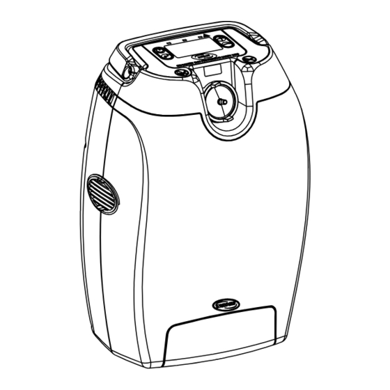
NOTE: The inlet filter should be replaced according to the Transportable Oxygen Concentrator Preventive Maintenance Record on page 23. 1. Position Transportable Oxygen Concentrator flat on the backside of unit to locate the inlet filter access door (DETAIL “A”). 2. Using a #2 Phillips® screw driver, remove the retaining screw securing the inlet filter access door to unit (DETAIL “B”). 3. Remove inlet filter access door from unit. 4. Locate existing inlet filter and remove (DETAIL “C”). 5. Install new replacement inlet filter. 6. Reinstall inlet filter access door by inserting tabs into the slots located on the unit. 7. Reinstall retaining screw to secure the inlet filter access door. NOTE: Use only Invacare replacement Part Number 1157083 (Inlet Filter) on the Transportable Oxygen Concentrator. DETAIL “B” DETAIL “A” Filter Access Door Screw DETAIL “C” Inlet Filter FIGURE 2.2 Replacing the Inlet Filter ™... -
Page 12: Replacing The Patient Outlet Filter
SECTION 2—COMPONENT REPLACEMENT Replacing the Patient Outlet Filter NOTE: For this procedure, refer to FIGURE 2.3. NOTE: The patient outlet filter should be replaced according to the Transportable Oxygen Concentrator Preventive Maintenance Record on page 23. 1. With the Transportable Oxygen Concentrator in the upright position, locate the patient outlet filter. 2. Place fingers on patient outlet filter and turn counter clockwise to loosen (DETAIL “A”). 3. Remove patient outlet filter and o‐ring from unit (DETAIL “B”). 4. Install new patient o‐ring onto unit. 5. Install patient outlet filter. A. Hand tighten by turning clockwise until secure. NOTE: Use only Invacare replacement Part Number 1164372 (Patient Outlet Filter Kit) on the Transportable Oxygen Concentrator. DETAIL “A” Patient Outlet Filter DETAIL “B” Shown without Shown O-Ring with O-Ring FIGURE 2.3 Replacing the Patient Outlet Filter... -
Page 13: Section 3-Checking O 2 Purity
SECTION 3—CHECKING O PURITY SECTION 3—CHECKING O PURITY NOTE: Oxygen purity should be checked every 3 yrs or 26,280 hours, whichever comes first. Refer to Transportable Oxygen Concentrator Preventive Maintenance Record on page 23. 1. Turn the unit On by pressing the On/Off button 2. Adjust flow to 3.0 LPM continuous (refer to owner’s manual), allow to run for a minimum of 8 minutes. 3. Connect a standard hand held oxygen analyzer to the outlet port. 4. Follow the directions provided by the analyzer manufacturer. 5. Repeat steps 2‐4 for continuous flow settings 2.5, 2.0, 1.5, 1.0 and 0.5. ™ Part No 1164898 SOLO... -
Page 14: Section 4-Administrative Settings Screen
SECTION 4—ADMINISTRATIVE SETTINGS SCREEN SECTION 4—ADMINISTRATIVE SETTINGS SCREEN Accessing Administrative Settings Screen NOTE: For this procedure, refer to FIGURE 4.1. 1. From main menu operational screen (DETAIL “A”) simultaneously press the Return/ Highlight , Up/Increase , and Down/Decrease Button to access the administrative settings screen (DETAIL “B”). Main Menu DETAIL “A” Operational Screen On/Off Up/Increase Button Button Display Return/ Down/Decrease Highlight Button Button DETAIL “B” Administrative Settings Screen FIGURE 4.1 Accessing Administrative Settings Screen Resetting Patient Hours NOTE: For this procedure, refer to FIGURE 4.1. -
Page 15: Adjusting Dc Power Limit
Adjusting DC Power Limit NOTE: For this procedure, refer to FIGURE 4.1 on page 14. 1. Enter administrative settings screen (DETAIL “B”). Refer to Accessing Administrative Settings Screen on page 14 for this procedure. 2. Locate the DC Power Limit setting (DETAIL “B”). A. Press the Up/Increase or Down/Decrease button to highlight DC Power Limit setting. B. Press the Return/Highlight button to relocate highlight bar to the adjustable setting on right side of screen. 3. Press the Up/Increase or Down/Decrease button to adjust Power Limit. NOTE: Maximum DC Power Limit is 2.0 LPM Continuous. 4. Save changes by pressing the Return/Highlight button to relocate highlight bar to left side of screen. NOTE: Changes are not saved until the highlight bar is relocated to the left side of the screen. 5. Press and hold the Return/Highlight button to return to the main menu operational screen. NOTE: The Transportable Oxygen Concentrator will automatically return to the main menu operational screen if idle for a period of approximately 10‐15 seconds. NOTE: The Transportable Oxygen Concentrator is preset by Invacare at a maximum setting of 2.0 ™ Part No 1164898 SOLO... -
Page 16: Toggling Auto Pulse
SECTION 4—ADMINISTRATIVE SETTINGS SCREEN Toggling Auto Pulse NOTE: For this procedure, refer to FIGURE 4.1 on page 14. 1. Enter administrative settings screen (DETAIL “B”). Refer to Accessing Administrative Settings Screen on page 14 for this procedure. 2. Locate the Auto Pulse setting (DETAIL “B”). A. Press the Up/Increase or Down/Decrease button to highlight Auto Pulse setting. B. Press the Return/Highlight button to relocate highlight bar to the adjustable setting on right side of screen. 3. Press the Up/Increase or Down/Decrease button to toggle between ON or OFF. 4. Save changes by pressing the Return/Highlight button to relocate highlight bar to left side of screen. NOTE: Changes are not saved until the highlight bar is relocated to the left side of the screen. 5. Press and hold the Return/Highlight button to return to the main menu operational screen. NOTE: The Transportable Oxygen Concentrator will automatically return to the main menu operational screen if idle for a period of approximately 10‐15 seconds. NOTE: Unit will remain in Auto Pulse mode until Auto Pulse is returned to “OFF”. ™ SOLO Part No 1164898... -
Page 17: Section 5-Troubleshooting And Maintenance
SECTION 5—TROUBLESHOOTING AND MAINTENANCE SECTION 5—TROUBLESHOOTING AND MAINTENANCE Functional Test NOTE: For this procedure, refer to FIGURE 5.1. 1. Install battery in unit. 2. Verify communication exists between the Transportable Oxygen Concentrator and the battery (DETAIL “A”) by momentarily pressing the “ON/OFF” button. 3. Connect Transportable Oxygen Concentrator to AC power source. • Screen will light up displaying the AC power icon, battery %, bars on battery symbol that correspond to the battery % and the charging icon if battery is not at 100% (DETAIL “B”). DETAIL “A” DETAIL “B” DETAIL “C” FIGURE 5.1 Functional Test 4. Turn the Transportable Oxygen Concentrator on by pressing the “ON/OFF” button for approximately 2‐3 seconds, not to exceed 5 seconds. NOTE: When the Transportable Oxygen Concentrator is turned on, the green LED will illuminate to show unit is in operation. 5. -
Page 18: Checking Outlet Hepa Filter
SECTION 5—TROUBLESHOOTING AND MAINTENANCE 7. After oxygen purity has been checked, change setting to pulse flow. Refer to the Transportable Oxygen Concentrator Owner’s Manual for this procedure. 8. After approximately sixty seconds of operation the “No Breath Found” warning screen will display (DETAIL “C”), yellow LED will illuminate and flash repeatedly, and a triple beep will sound in 10 second intervals. 9. Verify that the “No Breath Found” alarm is operating as defined by the Transportable Oxygen Concentrator owner’s manual. 10. Connect an oxygen cannula to the Transportable Oxygen Concentrator. 11. Breathe with the cannula to ensure the Transportable Oxygen Concentrator pulses at each setting (DETAIL “C” will disappear). Change setting as required. 12. Turn unit off by pressing the “ON/OFF” button for approximately 2‐3 seconds and unplug the AC power cord. Leave battery installed. 13. Press the “ON/OFF” button for approximately 1 second. The display should illuminate displaying the main operational screen (DETAIL “A”). 14. Turn unit on by pressing the “ON/OFF” button for approximately 2‐3 seconds. Verify unit starts and allow unit to run for 30 seconds. 15. Turn unit off to complete test. Checking Outlet HEPA Filter NOTE: Recommended to be replaced between patients. 1. Turn unit on by pressing the “ON/OFF” button for approximately 2‐3 seconds. -
Page 19: Troubleshooting Alarms
To access the Alarm codes, the unit first has to be in an alarm condition with the red LED illuminated. While in this condition: 1. Push the ON/OFF and Up/Increase flow setting buttons simultaneously. • Six numbers will display at the bottom of the screen, refer to FIGURE 5.2 on page 19. The first is the total number of errors occurring, the second number is the error sequence (current error displayed beginning with “0”), and the last four numbers are the error codes. Refer to Error Codes on page 20. • If more than one error occurs use the Return/Highlight button to cycle through each error. Once the unit is turned off, the alarm codes will reset. All the alarms should be reset and the unit turned back on to see if the unit can self‐correct the problem. NOTE: If the alarm persists, please contact your nearest Invacare repair center. 3330 Error Code # of Errors Error Sequence FIGURE 5.2 Accessing Alarm Codes ™ Part No 1164898 SOLO... -
Page 20: Error Codes
SECTION 5—TROUBLESHOOTING AND MAINTENANCE Error Codes ERROR CODE DESCRIPTION COMMENT Common Alarms Warning - Battery less than 25% Charge battery, see Owner’s Manual Warning - Battery less than 15% Charge battery, see Owner’s Manual Warning - No Breath Found Check Canula 1024 Warning - Battery less than 10% Charge battery, see Owner’s Manual... - Page 21 SECTION 5—TROUBLESHOOTING AND MAINTENANCE ERROR CODE DESCRIPTION COMMENTS System Alarms 0000 Alarm - No alarm Call Provider 2816 Alarm - Corrupt scheduler 2817 Alarm - Watch dog time-out 2818 Alarm - ee Writer no verified 2819 Alarm - ee Recover lower 2820 Alarm - ee Memory corrupted 2821...
- Page 22 SECTION 5—TROUBLESHOOTING AND MAINTENANCE 2858 Alarm - Dsp Bios Hw Int 2859 Display - Holding spi during ee read request Alarm - gpio exp driver i2c response time 2860 2861 Alarm - Wait for V12 off time out 2862 Alarm - Wait for V12 on time out Alarm - Gpio exp driver wait to acquire i2c 2863 time out...
-
Page 23: Transportable Oxygen Concentrator Preventive Maintenance Record
SECTION 5—TROUBLESHOOTING AND MAINTENANCE Transportable Oxygen Concentrator Preventive Maintenance Record Model No. ________________________ Serial No._________________________ ON EACH INSPECTION Record Date Of Service Record Elapsed Hours On Hour Meter Clean Cabinet Filter(s) Check Prescribed L/min Flow Rate EVERY 26,280 HOURS OR 3 YEARS, WHICHEVER COMES FIRST Check Oxygen Concentration DURING PREVENTATIVE MAINTENANCE SCHEDULE, OR BETWEEN PATIENTS Clean/Replace Cabinet... -
Page 24: Limited Warranty
LIMITED WARRANTY For warranty information, please refer to the original owner's manual which came with this product, or contact Invacare for more information. www.invacare.com Invacare Corporation Canada All rights reserved. Trademarks are One Invacare Way 570 Matheson Blvd E Unit 8 identified by ™...
Need help?
Do you have a question about the Solo2 TPO100B and is the answer not in the manual?
Questions and answers