Table of Contents
Advertisement
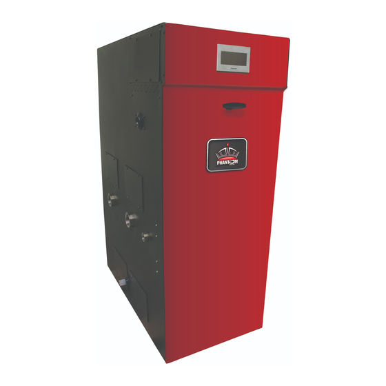
High Efficiency Gas-Fired Hot Water
Direct Vent Condensing Boilers
INSTALLATION AND OPERATING INSTRUCTIONS
These instructions must be affixed on or adjacent to the boiler and
retained for future reference.
Models:
• PHNTM210
• PHNTM285
This manual is for use with
boilers having a part number
ending in "B" (example:
PHNTM285HNT1SUB).
105357-05 -7/15
Manufacturer of Hydronic Heating Products
P.O. Box 14818 3633 I. Street
Philadelphia, PA 19134
www.crownboiler.com
Series
WARNING:
Improper installation, adjustment, alteration,
service or maintenance can cause property damage, injury,
or loss of life. For assistance or additional information,
consult a qualified installer, service agency or the gas
supplier. This boiler requires a special venting system.
Read these instructions carefully before installing.
9700609
Advertisement
Table of Contents

Related Manuals for Crown Boiler Phantom-X PHNTM210


Summary of Contents for Crown Boiler Phantom-X PHNTM210
-
Page 1: Installation And Operating Instructions
Series High Efficiency Gas-Fired Hot Water Direct Vent Condensing Boilers INSTALLATION AND OPERATING INSTRUCTIONS These instructions must be affixed on or adjacent to the boiler and retained for future reference. 9700609 Models: WARNING: Improper installation, adjustment, alteration, service or maintenance can cause property damage, injury, •... - Page 2 IMPORTANT INFORMATION - READ CAREFULLY NOTE: The equipment shall be installed in accordance with those installation regulations enforced in the area where the installation is to be made. These regulations shall be carefully followed in all cases. Authorities having jurisdiction shall be consulted before installations are made.
- Page 3 Special Installation Requirements for Massachusetts A. For all sidewall horizontally vented gas fueled equipment installed in every dwelling, building or structure used in whole or in part for residential purposes and where the sidewall exhaust vent termination is less than seven (7) feet above grade, the following requirements shall be satisfied: 1.
-
Page 4: Table Of Contents
TABLE OF CONTENTS Product Description, Specifications and Dimensional Data...... Unpacking Boiler..................III. Pre-Installation and Boiler Mounting ............Venting...................... A. General Guidelines................14 B. CPVC/PVC Venting................19 C. Polypropylene Venting................. 25 D. Stainless Steel Venting................ 28 E. Removing the Existing Boiler............... 31 F. -
Page 5: Product Description, Specifications And Dimensional Data
I. Product Description, Specifications and Dimensional Data Phantom Series boilers are condensing high efficiency Pressure Vessel Code, which provide a maximum heat gas-fired direct vent hot water heating boilers designed transfer and simultaneous protection against flue gas product for use in forced hot water space heating systems requiring corrosion. -
Page 8: Unpacking Boiler
I. Product Description, Specifications and Dimensional Data (continued) Table 2: Ratings Phantom Series Gas-Fired Boilers Input (MBH) Output AFUE Net AHRI Ratings Water Model Number (MBH) (MBH) Min. Max. PHNTM210 95.0 PHNTM285 95.0 Ratings shown are for installations at sea level and elevations up to 2000 ft. For elevations above 2000 ft., the boiler will naturally derate by 2.5% for each 1000 ft. -
Page 9: Pre-Installation And Boiler Mounting
USA - National Fuel Gas Code, ANSI Crown Boiler Company DOES NOT warrant Z223.1/NFPA 54, Air for Combustion and Ventilation; failures caused by mis-sized boiler applications. - Page 10 III. Pre-Installation and Boiler Mounting (continued) G. General Boiler Clearances to Combustible (and Non- Combustible) Material: 1. Phantom boilers are intended for All models are listed for closet installation with the installations in an area with a floor drain or in following minimum clearances –...
- Page 11 III. Pre-Installation and Boiler Mounting (continued) Minimum Listed Direct Vent Pipe Vent Pipe Clearance to Vent Pipe Material Enclosure Vent System Direction Nominal Diameter Combustible Material Factory Standard 3 in. (80 mm) * CPVC/PVC 1 in. (25 mm) Two-Pipe CPVC/PVC Vent and PVC Combustion 4 in.( 100 mm) Air Intake 3 in.
- Page 12 III. Pre-Installation and Boiler Mounting (continued) H. Boiler Stacking • The remaining lower bracket hole must align with a matching bottom boiler left side panel 1. For installations with unusually high space top positioning dimple. heating and/or domestic hot water heating loads, •...
- Page 13 III. Pre-Installation and Boiler Mounting H. Boiler Stacking (continued) to drain disposal is permissible, providing piping selection/sizing based on combined common pipe has sufficient flow capacity heating capacity and/or gross output of the selected stackable boiler combination. to handle combined condensate volume of stackable combination.
-
Page 14: Venting
IV. Venting WARNING Asphyxiation Hazard. Failure to vent this boiler in accordance with these instructions could cause products of combustion to enter the building resulting in severe property damage, personal injury or death. Do not use a barometric damper, draft hood or vent damper with this boiler. Do not locate vent termination under a deck. - Page 15 IV. Venting A. General Guidelines (continued) Table 4: Vent/Combustion Air System Options Compo- Approved Direct Vent Orientation Termination Description Figures nent Part Vent System Material Table The system includes separate CPVC vent Standard pipe and PVC air intake pipe terminating 4, 5, 6A, 6B, (through sidewall) through sidewall with individual penetrations...
- Page 16 IV. Venting A. General Guidelines (continued) Figure 4: Location of Vent Terminal Relative to Windows, Doors, Grades, Overhangs, Meters and Forced Air Inlets - Two-Pipe System Vent Terminal (Shown) Two-Pipe System Air Intake Terminal (Not Shown) Table 6A: Vent System and Combustion Air System Components Equivalent Length vs.
- Page 17 IV. Venting A. General Guidelines (continued) Table 6B: Vent/Combustion Air Equivalent Length Calculation Work Sheet Combustion Air Vent 90° Elbow(s) (Installer Supplied) 90° Elbow(s) (CPVC Supplied with Boiler) Subtotal, Subtotal, Quantity Equivalent Quantity Equivalent Length, Nominal Diameter Equivalent Nominal Diameter Equivalent (Pc) Length, per Pc...
- Page 18 IV. Venting A. General Guidelines (continued) b. Maintain correct clearance and orientation between vent and combustion air terminals. Space centerlines of vent and combustion air terminals minimum 12 in. (300 mm) apart. More than 12 in. (300 mm) spacing is recommended.
-
Page 19: Cpvc/Pvc Venting
IV. Venting A. General Guidelines - B. CPVC/PVC Venting (continued) m. Under certain conditions, water in the flue gas may condense, and possibly freeze, on objects around the terminal including on the structure itself. If these objects are subject to damage by flue gas condensate, they should be moved or protected. - Page 20 IV. Venting B. CPVC/PVC Venting (continued) Figure 8: Direct Vent - Vertical Terminations with Sloped Roof Extend vent/combustion air piping to maintain minimum vertical (‘X’) and minimum horizontal (‘Y’) distance of 12 in. (300 mm) [18 in. (460 mm) Canada] from roof surface. Allow additional vertical (‘X’) distance for expected snow accumulation.
- Page 21 IV. Venting B. CPVC/PVC Venting (continued) Table 7B: CPVC/PVC Vent & Air Intake Components (Installer Provided) Required for Optional Horizontal (Snorkel) Termination Quantity Part PHNTM210 PHNTM285 Vent Components Number Horizontal (Snorkel) Horizontal (Snorkel) Termination Termination 3 in. Schedule 40 PVC Pipe x up to 7 ft. max. vertical run 4 in.
- Page 22 IV. Venting B. CPVC/PVC Venting (continued) Figure 10: Near-Boiler Vent/Combustion Air Piping - Floor Mounted Boiler Builds c. Attach flue temperature sensor wiring harness d. Insert Schedule 40 PVC combustion air pipe (taped to boiler rear panel) female connectors to (installer provided) into the combustion air the sensor male spade terminals.
- Page 23 IV. Venting B. CPVC/PVC Venting (continued) Table 8: Expansion Loop Lengths Nominal Length of Loop Length Pipe Dia. Straight Run “L” (In.) (In.) (Ft.) Figure 11: CPVC/PVC Expansion Loop and Offset • PVC vent pipe must be installed in such way as to permit adequate air circulation around the outside of the pipe to prevent internal wall temperature rising above...
- Page 24 IV. Venting B. CPVC/PVC Venting (continued) ii. Combustion Air Piping opening to provide weather-tight seal. • After penetrating wall, install a Schedule Sealant should not restrain the expansion 40 PVC 90° elbow so that elbow leg is in of the vent pipe. the up direction.
-
Page 25: Polypropylene Venting
IV. Venting B. CPVC/PVC Venting - C. Polypropylene Venting (continued) C. Polypropylene Venting Install storm collar on vent pipe immediately above flashing. Apply Dow Corning Silastic 732 RTV Sealant or equivalent between vent WARNING pipe and storm collar to provide Asphyxiation Hazard. - Page 26 IV. Venting C. Polypropylene Venting (continued) Table 10A: Approved Polypropylene Pipe, Fittings and Terminations - M&G/DuraVent M&G / DuraVent Part Numbers/Sizes Chimney Boiler Boiler Boiler Male Boiler Pipe Joint Side Wall Kit for Model Adapter, PVC Adapter Adapter, Rigid Pipe Flex Pipe Locking Termination...
- Page 27 IV. Venting a. Models PHNTM210 and PHNTM285 are listed C. Polypropylene Venting (continued) for vertical venting by installing flexible vent in an UNUSED masonry chimney/chase and supplying combustion air through a separate wall WARNING or roof combustion air terminal. Asphyxiation Hazard. Vent systems made by b.
-
Page 28: Stainless Steel Venting
IV. Venting D. Stainless Steel Venting (continued) Venting of Other Appliances (or Fireplace) into Chase or Adjacent Flues Prohibited! D. Stainless Steel Venting Figure 15: Flexible PP Vent in Masonry Chimney with Separate Combustion Air Intake WARNING NOTICE Asphyxiation Hazard. Follow these instructions Do not exceed maximum vent/combustion and the installation instructions included by air system length. - Page 29 IV. Venting D. Stainless Steel Venting (continued) combustion air piping sections with any general- a. Plan venting system to avoid possible contact purpose silicone sealant such as GE RTV102. with plumbing or electrical wires. Start at Seal PVC combustion air piping sections with vent connector at boiler and work towards vent PVC cement.
- Page 30 IV. Venting D. Stainless Steel Venting (continued) Table 11: Acceptable Stainless Steel Vent Systems and Vent Components Vent PVC to SS Horizontal Vertical Manufacturer Nominal Dia. Wall Thimbles System Adapter Termination Termination 4 in. M&G/DuraVent FasNseal 810005231 FSWT4 Tee: FSTT4 FSBS4 (100 mm) SVE Series III...
-
Page 31: Removing The Existing Boiler
IV. Venting D. Stainless Steel Venting, E.. Removing the Existing Boiler (continued) a. Both models are listed for vertical venting by system placed in operation, while the other appliances installing flexible stainless steel vent (M&G/ remaining connected to the common venting system are DuraVent FlexNSeal brand) in an UNUSED not in operation. -
Page 32: Multiple Boiler Installation Venting
IV. Venting E.. Removing the Existing Boiler, F. Multiple Boiler Installation Venting (continued) 2. Inspecter de façon visuelle le système d’évcuation pour déterminer la grosseur et l’inclinaison horizontale qui conviennent et s’assurer que le WARNING système est exempt d’obstruction, d’étranglement, Asphyxiation Hazard. - Page 33 IV. Venting F. Multiple Boiler Installation Venting (continued) Figure 17 : Flexible Stainless Steel Vent in Masonry Chimney with Separate Combustion Air Intake Figure 18: Multiple Boiler Direct Vent Termination...
-
Page 34: Condensate Disposal
V. Condensate Disposal A. Condensate Trap and Drain Line 1. All condensate which forms in the boiler or vent WARNING system collects in the sump under heat exchanger Asphyxiation Hazard. Failure to fill the and leaves the boiler through factory installed condensate trap with water prior to boiler start- condensate trap. - Page 35 V. Condensate Disposal (continued) Table 11C: Maximum Condensate Flow Boiler *Maximum Condensate Flow, Model PHNTM210 PHNTM285 *Assumes 100% of water in fuel condenses. Figure 19: Condensate Trap and Drain Line...
-
Page 36: Water Piping And Trim
Oxygen contamination of boiler water will cause corrosion of iron and steel boiler components, and can lead to boiler failure. Crown Boiler Company’ s Standard Warranty does not cover problems caused by oxygen contamination of boiler water or scale (lime) build-up caused by frequent addition of water. - Page 37 VI. Water Piping and Trim B. Piping System To Be Employed (continued) 1. Near boiler piping must isolate boiler from b. Install close nipple into tee branch, then, screw the assembly into boiler left side front ¾ in. system piping via closely spaced tees to insure tapping making sure tee run outlets are in vertical specified flow range through boiler any time the...
- Page 38 VI. Water Piping and Trim B. Piping System To Be Employed (continued) Table 12: Flow Range Requirement Through Boiler Boiler Boiler Minimum Boiler Required Boiler Required Boiler Maximum Boiler Boiler Supply Return Required Head Loss, Flow, Head Loss, Flow, Head Loss, Required Head Loss, Model...
- Page 39 VI. Water Piping and Trim C. Standard Installation Requirements (continued) Table 14: Fitting and Valve Equivalent Length Table 14: Fitting and Valve Equivalent Length (cont’d) Copper Fitting and Sweat Valve Equivalent Length (Ft) Threaded Fitting and Valve Equivalent Length (Ft) Copper Pipe or Valve Size Black Threaded Pipe or Fitting or Valve...
- Page 42 VI. Water Piping and Trim D.Special Situation Installation Requirements, E. Multiple Boiler Installation (continued) volume taken after initial fill and eliminate any • Radiant systems employing tubing without water leakage as early as possible. oxygen barrier 5. Automatic Air Vent (Required) –At least one •...
- Page 45 VI. Water Piping and Trim E. Multiple Boiler Installation (continued) NOTICE The Phantom boiler heat exchanger is made from stainless steel tubular coil having relatively narrow waterways. Once filled with water, it will be subject to the effects of corrosion. Failure to take the following precautions to minimize corrosion and heat exchanger waterways overheating could result in severe boiler damage.
-
Page 46: Gas Piping
VII. Gas Piping 2. Maximum gas demand . Refer to the boiler’s input as printed on its rating label. Also consider WARNING existing and expected future gas utilization Explosion Hazard. Failure to properly pipe gas equipment (i.e. water heater, cooking equipment). supply to boiler may result in improper operation 3. - Page 47 VII. Gas Piping (continued) Table 17B: Maximum Capacity of Schedule 40 Black Pipe in CFH* (LP Gas) For Gas Pressures of 0.5 psig or Less Inlet Pressure 11.0 Inch W.C.; 0.3 Inch W.C. Pressure Drop Nominal Inside Length of Pipe, Ft. Pipe Size, In.
- Page 48 VII. Gas Piping (continued) Table 19: Specific Gravity Correction Factors 4. All above ground gas pipin g upstream Specific Correction Specific Correction from manual shut-off valve must be electrically Gravity Factor Gravity Factor continuous and bonded to a grounding electrode. Do 0.60 1.00 0.90...
- Page 49 VII. Gas Piping (continued) E. Gas Piping for Multiple Boiler Installation 1. Individual module (boiler) gas pipe sizing CAUTION specific details - see Paragraph A. If gas pressure in the building is above ½ psig 2. Individual module (boiler) recommended gas (3.4 kPa), an additional gas pressure regulator piping detail - see Figure 25.
-
Page 50: Electrical
VIII. Electrical DANGER Electrical Shock Hazard. Positively assure all electrical connections are unpowered before attempting installation or service of electrical components or connections of the boiler or building. Lock out all electrical boxes with padlock once power is turned off. WARNING Electrical Shock Hazard. - Page 51 VIII. Electrical (continued) C. Refer to Figures 26 and 27 for details on the wiring should be routed away from sources of electrical noise. Where it is impossible to avoid such internal boiler wiring. noise sources, wire the sensor using a 2 conductor, Line Voltage (120 VAC) Connections - see Figure 26.
- Page 54 VIII. Electrical (continued) Figure 27: Ladder Diagram...
- Page 55 VIII. Electrical (continued) Figure 28A: Modified Wiring For DHW Priority When Using Low Flow Circulator Piped Off System Header - Heating (with Central Heating Circulators) Plus Alternately Piped Indirect Water Heater...
- Page 57 VIII. Electrical (continued) CROWN PN 3501505 Figure 28C: DHW Priority/Circulators (with Crown PN 3501505 Zone Panel) Piped Off System Header Wiring Schematic for Heating Zone Circulators...
- Page 60 VIII. Electrical (continued) c. RJ45 Splitters G. Multiple Boiler Operating Information When Ethernet cables are used to connect three 1. Required Equipment and Setup or more boilers together, RJ45 Splitters are required. When two boilers are connected the a. Header Sensor (Honeywell 32003971-003) splitter is not required.
- Page 61 VIII. Electrical (continued) d. Multiple Boiler Setup Step Description Comments Wire the header sensor to low voltage terminal strip terminals “Header sensor”. Install and wire the Header NOTE Sensor This step can not be skipped. The Sequence Master can not be “enabled”unless a Header Sensor is installed.
-
Page 62: System Start-Up
IX. System Start-up F. Prepare to check operation. 1. Obtain gas heating value (in Btu per cubic foot) WARNING from gas supplier. Explosion Hazard. Asphyxiation Hazard. 2. Phantom gas valves have inlet and outlet Electrical Shock Hazard. Start-up of this boiler pressure taps with built-in shut off screw. - Page 63 IX. System Start-up (continued) Phantom Series Lighting and Operating Instructions Figure 32: Operating Instructions...
- Page 64 IX. System Start-up (continued) J. Check Gas Inlet Pressure Status Control Action Check the inlet pressure and adjust if necessary. Verify Initiate Power-up that the inlet pressure is between the upper and lower This state is entered when a delay is limits shown on the rating plate with all gas appliances Standby Delay needed before allowing the burner control...
- Page 65 IX. System Start-up (continued) to both gas valves equally and simultaneously. a. Lock boiler in high fire and allow boiler to Refer to Figure 34 for location of throttle screw. operate for approximately 5 minutes before Verify CO is less than 100 ppm. taking combustion readings.
- Page 66 IX. System Start-up (continued) M. Test Safety Limits Controls 1. Test the ignition system safety shut-off WARNING disconnecting the flame sensor connector (black Explosion Hazard. Asphyxiation Hazard. plug with orange wire) from the flame ionization This conversion should be performed by a electrode.
- Page 67 IX. System Start-up (continued) 6. Verify that the gas inlet pressure is between the Table 24: Number of Clockwise Throttle Screw upper and lower limits shown in Table 20 with all Turns for LP Conversion gas appliances (including the converted boiler) both Throttle Screw Turns at on and off.
- Page 68 IX. System Start-up (continued) Table 25A: Approximate Throttle Screw Table 25B: Approximate Throttle Screw Adjustment Values from Fully Closed Adjustment Values from Fully Closed Position, Natural Gas Position, LP Gas Boiler Throttle Position Boiler Throttle Position (Number of Counter- Model (Number of Counter-clockwise Turns Model clockwise Turns from Fully Closed...
- Page 69 IX. System Start-up (continued) S. Controls Startup Check List The Control is factory programmed with default parameters. Before operating the boiler, these parameters must be checked and adjusted as necessary to conform to the site requirements. Follow the steps below, making selections and adjustments as necessary to ensure optimal boiler operation.
-
Page 70: Operation
X. Operation A. Overview 5. Built-in Safety Control The Control includes safety controls designed to ensure 1. R7910 Controller safe and reliable operation. In addition to flame safety The R7910 Controller (Control) contains features and controls the Control includes supply water temperature, capabilities which help improve heating system operation, differential water temperature, and stack temperature and efficiency. -
Page 71: Supply Water Temperature Regulation
X. Operation B. Supply Water Temperature Regulation 5. Outdoor Air Reset If an outdoor temperature sensor is connected to the 1. Priority Demand boiler and Outdoor Reset is enabled, the Central Heat The Control accepts a call for heat (demand) from multiple and Auxiliary Heat setpoints will automatically adjusted places and responds according to it’s “Priority”. -
Page 72: Boiler Protection Features
X. Operation C. Boiler Protection Features 5. Boiler Mounted Limit Devices The Control monitors individual limit devices: 1. Supply Water Temperature High Limit pressure switch, high limit device, condensate level The boiler is equipped with independent automatic switch, Thermal Link (ALP285B only), Burner Door reset and a manual reset high limit devices. -
Page 73: Multiple Boiler Control Sequencer
X. Operation 6. Multiple Demands D. Multiple Boiler Control Sequencer The Sequence Master responds to Central Heat, Auxiliary 1. “Plug & Play” Multiple Boiler Control Sequencer Heat DHW and frost protection demands similar to the When multiple boilers are installed, the Control’s stand alone boiler. -
Page 74: Boiler Sequence Of Operation
X. Operation E. Boiler Sequence of Operation 1. Normal Operation Table 28: Boiler Sequence of Operation Status Screen Display Description Priority: (burner Off, circulator(s) Off) Standby Boiler is not firing and there is no call for heat, priority equals standby. The boiler Status: is ready to respond to a call for heat. -
Page 75: Using The Display
X. Operation E. Boiler Sequence Of Operation (continued) 2. Using The Display The Control includes a touch screen LCD display. The user monitors and adjusts boiler operation by selecting screen navigation “buttons” and symbols. The “Home Screen” and menu selections are shown below. When no selection is made, while viewing any screen, the display reverts to the “Home Screen”... -
Page 76: Viewing Boiler Status
X. Operation E. Boiler Sequence Of Operation (continued) 3. Status Screens Boiler Status screens are the primary boiler monitoring screens. The user may simply “walk” though boiler operation by repeatedly selecting the right or left “arrow” symbol. These screens are accessed by selected the “Status”... - Page 77 X. Operation E. Boiler Sequence Of Operation (continued) 3. Status Screens (continued) Bargraph Screen Bargraph Screen The bargraph screen presents measured values for easy comparison. Included on this screen is firing rate and when the Zone Panel is connected the measure Heat Loss. Measured heat loss is the heat rate kbtu/hr sum of all active (call for heat) zones.
-
Page 78: Detail Screens
X. Operation E. Boiler Sequence Of Operation (continued) Circulator Status Screen Pumping is a major part of any hydronic system. This screen provides the status of the boiler’s demand to connected pumps as well as the status of Frost Protection and pump Exercise functions. Head Demand Screen This screen provides the status of the boilers five (5) possible heat demands. -
Page 79: Multiple Boiler Sequencer Screens
X. Operation E. Boiler Sequence Of Operation (continued) 5. Multiple Boiler Sequencer Screens available When the Sequence Master is enabled the following screens are The Sequencer Status screen is selected by “pressing” “Status” button from the “Home” screen when Sequence Master is enabled. -
Page 80: Changing Adjustable Parameters
X. Operation F. Changing Adjustable Parameters 1. Entering Adjust Mode The Control is factory programmed to include basic modulating boiler functionality. These settings are password protected to discourage unauthorized or accidental changes to settings. User login is required to view or adjust these settings: - Press the “Adjust”... - Page 81 X. Operation F. Changing Adjustable Parameters (continued) 2. Adjusting Parameters (continued) The following pages describe the Control’s adjustable parameters. Parameters are presented in the order they appear on the Control’s Display, from top to bottom and, left to right. From the “Home” screen select the Adjust button to access the adjustment mode screens show below (if required, refer to the previous page to review how to enter Adjustment mode): System “Press”...
- Page 82 X. Operation F. Changing Adjustable Parameters (continued) WARNING Asphyxiation Hazard. Boiler type is factory set and must match the boiler model. Only change the boiler type setting if you are installing a new or replacement Control. The boiler type setting determines minimum and maximum blower speeds.
- Page 83 X. Operation F. Changing Adjustable Parameters (continued) Expected Heat Rate Adjustment Screens (HeatMatch Software) The Control is shipped with defaults that will provide improved operation. Adjustment is only required to optimize setup. The expected heat rate adjustment is used to better match boiler output to the home heating needs. After receiving a "call for heat"...
- Page 84 X. Operation F. Changing Adjustable Parameters (continued) Modulation “Press” button to access the following parameters: Setup Factory Range / Choices Parameter and Description Setting Central Heat Maximum Expected Heat Rate Minimum to This parameter defines the highest modulation rate the Control will go to during a central heat 100% Maximum call for heat.
- Page 85 X. Operation F. Changing Adjustable Parameters (continued) “Press” Pump Setup button to access the following parameters: Factory Setting Range / Choices Parameter and Description System Pump run pump for: Activates the system pump output according to selected function. Never, Never: Pump is disabled and not shown on status screen.
- Page 86 X. Operation F. Changing Adjustable Parameters (continued) Example Pump Parameter selections (continued): Single boiler Indirect Water Heater (IWH)Piped to Primary, Optional Domestic Hot Water Priority. Parameter Selections: System Pump= “Central Heat , Optional Priority” Boiler Pump = “any demand” DHW Pump = “Primary Loop Piped IWH” DHW Priority Enable is optional Explanation: This piping arrangement permits the...
- Page 87 X. Operation F. Changing Adjustable Parameters (continued) Example Pump Parameter selections (continued): Multiple boilers IWH Piped to Primary, Optional Domestic Hot Water Priority Sequencer Master Boiler 2 (Boiler 1) Wiring locations: Thermostat DHW call for heat System pump DHW pump Boiler Pump Sequencer Master Parameter Selections: Sequencer Master...
- Page 88 X. Operation F. Changing Adjustable Parameters (continued) Contractor Setup “Press” button to access the following parameters: Contractor Name For Service Contact: Press box to input contractor information. Bill Smith > < Bill Smith 12 Victory Lane Plainview, New York Save 516 123-4567 Press SAVE button to store revisions.
- Page 89 X. Operation F. Changing Adjustable Parameters (continued) Central Heat “Press” button to access the following parameters: Factory Range / Choices Parameter and Description Setting 180°F 60°F to 190°F Central Heat Setpoint (82.2°C) (16°C to 87.8°C) Target temperature for the central heat priority. Value also used by the outdoor air reset function. Central Heat Thermostat “Sleep”...
- Page 90 X. Operation F. Changing Adjustable Parameters (continued) “Press” button to access the following parameters: Factory Range / Choices Parameter and Description Setting Auxiliary Heat Setpoint 180°F 60°F to 190°F Target temperature for the Auxiliary Heat priority. Value also used by the outdoor air reset (82.2°C) (16°C to 87.8°C) function.
- Page 91 X. Operation F. Changing Adjustable Parameters (continued) Domestic “Press” button to access the following parameters: Hot Water Factory Range / Choices Parameter and Description Setting Domestic Hot Water Setpoint 60°F (16°C) to The Domestic Hot Water (DHW) Setpoint parameter is used to create a minimum boiler water 170°F 190°F temperature setpoint that is used when DHW heat demand is “on”.
- Page 92 X. Operation F. Changing Adjustable Parameters (continued) “Press” button to access the following parameters: Factory Range / Choices Parameter and Description Setting Central Heat Outdoor Reset Enable If an outdoor sensor is installed and Outdoor Reset is Enabled, the boiler will automatically adjust the heating zone set point temperature based on the outdoor reset curve in Figure 45.
- Page 93 X. Operation F. Changing Adjustable Parameters (continued) “Press” button to access the following parameters: Factory Range / Choices Parameter and Description Setting Auxiliary Heat Outdoor Reset Enable If an outdoor sensor is installed and Outdoor Reset is Enabled, the boiler will automatically adjust the heating zone set point temperature based on the outdoor reset curve in Figure 45.
- Page 94 X. Operation F. Changing Adjustable Parameters (continued) Figure 45: Outdoor Reset Curve - Typical for Central Heat and Auxiliary Heat Central Heat Central Heat Heating Element Type Heating Element Type Setpoint Setpoint 180°F to 190°F 100°F to 140°F In Slab Radiant High Fan Coil (82.2°C to 87.8°C) (37.8°C to 60°C)
- Page 95 X. Operation F. Changing Adjustable Parameters (continued) “Press” button to access the following parameters: Factory Range / Choices Parameter and Description Setting Master Enable/Disable Enable, Disable The Sequencer Master Enable/Disable is used to “turn on” the Multiple Boiler Controller. Warning! Disable enable ONLY one Sequence Master.
- Page 96 X. Operation F. Changing Adjustable Parameters (continued) Sequence “Press” button to access the following parameters: Slave Factory Range / Choices Parameter and Description Setting Boiler Address Each boiler must be given a unique address. When ”Normal” slave selection order is used, the None boiler address is used by the Master Sequencer as the boiler start order.
- Page 97 X. Operation F. Changing Adjustable Parameters (continued) “Press” button to access the following parameters: Factory Range / Parameter and Description Setting Choices Central Heat Modulation Source This parameter enables the 4-20mA input to control firing rate and the thermostat input to control boiler on/off demand directly without using the internal setpoint.
-
Page 98: Service And Maintenance
XI. Service and Maintenance Important Product Safety Information Refractory Ceramic Fiber Product Warning: The Repair Parts list designates parts that contain refractory ceramic fibers (RCF). RCF has been classified as a possible human carcinogen. When exposed to temperatures above 1805°F, such as during direct flame contact, RCF changes into crystalline silica, a known carcinogen. - Page 99 XI. Service and Maintenance (continued) WARNING Asphyxiation Hazard. This boiler requires regular maintenance and service to operate safely. Follow the instructions contained in this manual. Improper installation, adjustment, alteration, service or maintenance can cause property damage, personal injury or loss of life. Read and understand the entire manual before attempting installation, start-up operation, or service.
- Page 100 XI. Service and Maintenance (continued) DANGER Explosion Hazard. Electrical Shock Hazard. Burn Hazard. This boiler uses flammable gas, high voltage electricity, moving parts, and very hot water under high pressure. Assure that all gas and electric power supplies are off and that the water temperature is cool before attempting any disassembly or service.
- Page 101 XI. Service and Maintenance (continued) acid or alkali products is prohibited. Do not use any cleaning agents or solvents. If insulation disc has signs CAUTION / ATTENTION of damage, it must be replaced. Electrical Shock Hazard. Label all wires prior to 8.
- Page 102 Remove 2 wire nuts and disconnect overflow switch 547-6002 and/or selected HVAC distributors. wire pigtails from boiler wiring. Contact Crown Boiler Company for specific c. Using pliers, release spring clip securing the details. overflow switch to condensate trap body and remove b.
- Page 103 XI. Service and Maintenance (continued) f. Reconnect the switch wire pigtails to the boiler steps from Condensate Overflow Switch Removal wiring and secure with wire nuts. and Replacement procedure above. g. Restore power supply to boiler. Fill up the trap j.
-
Page 104: Troubleshooting
XII. Troubleshooting WARNING Electrical Shock Hazard. Turn off power to boiler before working on wiring. A. Troubleshooting problems where no error code is displayed. Condition Possible Cause Boiler not responding to call for heat, “Status” and Boiler is not seeing call for heat. Check thermostat or zone wiring for loose connection, “Priority”... - Page 105 XII. Troubleshooting (continued) C. Help Screen Faults Indication Condition Possible Cause Crown Zone Panel 1 communication lost, typical for Panel 1 through 4: The zone panel’s communication was established and then lost. Check the following to correct the issue: Zone Panel 1 •...
- Page 106 XII. Troubleshooting (continued) E. Active Fault Screen Faults Indication Condition Possible Cause The Limit String Status screen shows the faulty safety limit. A contact icon, either Limit String Status “open” or “closed”, graphically represents each safety limit. The “closed” contact icon is steady;...
- Page 107 XII. Troubleshooting (continued) F. Troubleshooting problems where a Soft Lockout Code is displayed. When a soft lockout occurs, the boiler will shut down, the display will turn red and the “Help” button will “blink”. Select the “blinking” “Help” button to determine the cause of the soft lockout.
- Page 108 XII. Troubleshooting (continued) G. Troubleshooting problems where a Hard Lockout Code is displayed. When a hard lockout occurs, the boiler will shut down, the display will turn red and the “Help” button will “blink”. Select the “blinking” “Help” button to determine the cause of the Hard Lockout.
-
Page 109: Repair Parts
XIII. Repair Parts... - Page 110 XIII. Repair Parts (continued) Part Number Description PHNTM210 PHNTM285 Bare Heat Exchanger and Related Components (1B through 1E) Bare Heat Exchanger 101931-04 101931-05 Air Vent Valve 101586-01 Supply/Return Water Temp Sensor - (2 per boiler) 101685-01 High Limit 101653-01 Replacement Rear Insulation Disc 104856-01 Replacement Rear Insulation Disc and Thermal Link Switch Kit (Not Shown, 104998-01...
- Page 111 XIII. Repair Parts (continued) 2B-1 Part Number Description PHNTM210 PHNTM285 Blower 101529-01 101530-01 Blower Inlet Shroud Assembly [includes Gas Orifice; Gas Orifice O-Ring; (3x) M4x20 mm or (3x) M4x25 mm self-threading screws; Injector Plate; (4x) M4 x 10 mm flat head screws; 101704-03 101704-04 Air Intake Adapter - Air Connection Side;...
- Page 112 XIII. Repair Parts (continued) Part Number Description PHNTM210 PHNTM285 Repair Condensate Trap and Related Components Replacement Condensate Trap Kit 104704-01 Replacement Condensate Float Switch Kit 105005-01 Spring Clip, Condensate Trap - (2 per boiler) 101632-01 Rubber Grommet, Condensate Trap 101595-01 Air Pressure Switch 104426-01 9 in.
- Page 113 XIII. Repair Parts (continued) Part Number Description R7910 Kit (0 - 7000ft Altitude) 106193-01 R7910 Kit (7000 - 10000ft Altitude) 106193-02 106193-03 Programmed Display 106217-01 (with Mounting Hardware) Transformer 3502430...
- Page 114 XIII. Repair Parts (continued) Part Number Description PHNTM210 PHNTM285 Jacket, Rear/Bottom Panel 101217-04 101217-05 Replacement Left Side Panel Kit 105184-04 105184-05 (includes labels, access panels, grommets and header gaskets) Replacement Right Side Panel Kit 105183-04 105183-05 (includes labels, access panels and gaskets) Partition Shelf Assembly 102831-04 102831-05...
- Page 115 XIII. Repair Parts (continued) Quantity Vent System Components Part Number PHNTM210 PHNTM285 3” Schedule 40 PVC Tee Vent/Combustion Air Terminal 230803 4” Schedule 40 PVC Tee Vent/Combustion Air Terminal 230804 3” Stainless Steel Rodent Screens 230833 4” Stainless Steel Rodent Screens 230834 3”...
- Page 116 XIII. Repair Parts (continued) Part Number Description PHNTM210 PHNTM285 MISCELLANEOUS PARTS CARTON 103675-01 103676-01 Temperature/Pressure Gauge 950039 External Gas Shut Off Valve 950615 950600 Safety Relief Valve 30 PSI: 81660363 30 PSI: 95-040 Alternate Safety Relief Valve (Not Shown) 50 PSI: 103837-01 Boiler Drain Valve, 3/4”...
- Page 117 XIII. Repair Parts (continued) Part Number Key No. Description PHNTM210 PHNTM285 Complete Wiring Harness (includes 10A, 10B, 10C & 10D) 102701-03 Main (Low Voltage) Harness 103009-03 High Voltage Harness 103010-02 Blower Power Harness 103012-01 Communication Harness 103011-01 Igniter Harness 105752-01 Wiring Harness, Thermal Link &...
- Page 120 Manufacturer of Hydronic Heating Products P.O. Box 14818 3633 I. Street Philadelphia, PA 19134 www.crownboiler.com CBC PN 980132 Rev D, 7/15...
Need help?
Do you have a question about the Phantom-X PHNTM210 and is the answer not in the manual?
Questions and answers