Table of Contents
Advertisement
Quick Links
Advertisement
Table of Contents

Subscribe to Our Youtube Channel
Related Manuals for Zartek ZA-601


Summary of Contents for Zartek ZA-601
- Page 3 Do not attempt to repair by yourself. Please read this manual carefully to obtain optimum performance and extended service life from the system. For any queries please contact Zartek via email: info@zartek.co.za. Features • Digital transmission ensure interference free conversation •...
-
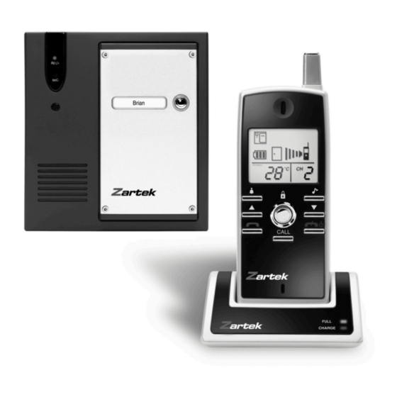
Page 4: Controls Layout
Controls Layout Outdoor Caller unit 1. Doorbell button 2. Doorbell indicator PAIRING 3. Microphone CHANNEL NORMAL 4. Speaker 1 2 3 5. Terminals for external connection 6. Channel switch (white) 7. Pairing switch (yellow) Handset and Charging Stand Outdoor ˚C CALL 1 2 3 4 8. - Page 5 LCD Icons Outdoor ˚C ˚F • Light up continuously • Flashing Icon Status Icon Status Frontgate doorbell ringing Door lock opened Backgate doorbell ringing ontgate battery low Missed call (Frontgate) • (Backgate) Backgate battery low Volume/door chime loudness Self battery low Conversation mode Battery level Door chime alert selected...
-
Page 6: Standard Items
Standard Items Outdoor ˚C CALL a. Handset d. AC adapter g. Tool b. Caller Unit e. Rechargeable Ni-MH battery pack h. Screws and rivets c. Charger stand f. Mounting bracket i. Instruction manual Setting the operating channel Outdoor Caller Unit PAIRING CHANNEL NORMAL... - Page 7 1. Unlock the caller unit from mounting bracket as per drawing. With the supplied tool, loosen the four screws that hold the aluminium cover and remove it. These screws are made special for anti- theft purpose, it is necessary to keep the tool in a safe place as you will need it later when replacing batteries.
- Page 8 Changing channels on handset 1. Press red on/off button 8 and call button 10 together. 2. Select channel (1-4) using arrow keys 14 and 15 . 3. Keep red on/off button 8 pressed to turn off handset to confirm channel selection. Selected handset channel must correspond to operating channel on the gate station Handset: 1 2 3 4...
- Page 9 AC/DC mains supply The caller unit can operate with 8-12V AC or DC supply. Connect the supply to the terminals 5 at the back marked with . In case of mains failure, the unit will automatically switch to supply 8-12V AC or DC from alkaline batteries (if installed).
- Page 10 1. Insert the supplied rechargeable battery pack into the battery compartment. Note the two exposed terminals on battery pack should come into contact with the battery spring 22 . 2. Put back the battery cover, with the handset remain switched off, place it into the charger stand. 3.
- Page 11 Pairing the Handset and Caller unit Handset Caller unit Step 1 PAIRING CHANNEL NORMAL 1 2 3 CALL Switch on the unit by a pressing the Set the yellow dip switch 7 to PAIRING button 8 while holding down the position.
- Page 12 Handset Caller unit Step 4 D i ! D i ! Beep! Beep! Outdoor ˚C CALL After 5-10 seconds, sound two beeps The “P” will stop flashing and remain steady confirming the handset has received the ID once the unit received the ID code. code and the door bell indicator 2 goes off.
- Page 13 The pairing process is now completed. To confirm if pairing is successful, insert batteries back in the caller unit, press doorbell button 1 , the handset should response. In the unlikely event you find any interference or receive false call from any nearby doorphone systems, repeat the pairing process again or switch to another channel.
- Page 14 Outdoor Outdoor ˚C ˚C CALL CALL Press button 8 momentarily to return Press button 8 momentarily to return to normal operation. to normal operation. N.B. All slave handsets can be cloned at the same time using one master handset. Programming other channels on same handset: •...
- Page 15 In the battery compartment of the handset the dip switch 21 for the back gate must be ON. Paired Handset Caller Unit (backgate) being cloned PAIRING CHANNEL NORMAL 1 2 3 Outdoor ˚C CALL Switch on unit by pressing button 8 Set the yellow dip switch 7 to PAIRING while holding down the button 9 .
-
Page 16: Gate Opening
Procedure: 1) Take the handset that has already been programmed to communicate with the front gate. Press the red button 8 and blue button 9 at the same time to get into programming mode. 2) Take the back gate caller station and ensure that the dip switches 6 are set the same channel as the handset. - Page 17 Auxiliary terminal (pins 3 & 4) These two terminals will provide a trigger output once the door bell button 1 is pressed. Such signal can be used to trigger on the conventional doorbell or trigger on a courtesy light at the entrance.
- Page 18 A relay board is needed to trigger the gate motor as the gate motor trigger activates from one pulse not an AC pulse, which is used by an electric door lock (see above). The relay board is an optional accessory available from Zartek. Part number for the relay board is GE-247.
- Page 19 4) To test the DC supply, remove one of the AA batteries and press any of the channel buttons. If the door station rings then the power connections are working but if no ring is sounded go back to stage 1. above and repeat the process of connecting the DC power. 5) Connect pin 1 on door station to 0 volts (ground) &...
-
Page 20: Operation
Operation Switching handset on and adjusting options: • Switch on the handset by a long press (3 seconds) of the button 8 . The LCD screen will show up. Press the same button again in case you want to switch off the unit. •... - Page 21 • Upon receiving a call, either icon (A) or icon (B) appears on the screen, depending if the call is from the front gate or back gate (in case you have purchased an optional caller unit for back gate). The handset can answer the call by pressing the button 9 , the icon (E) will show up on the screen correspondingly.
- Page 22 Alert signals and temperature reading • Under the circumstances of an unanswered call from a visitor (e.g. you are away from home or located at a place which is out of range from the caller unit), the icon (C) will appear on the screen.
-
Page 23: Troubleshooting Guide
Trouble Shooting Guide Problem Possible Causes Solution Communication range is short, and There may be many steel Relocate the position of Handset. audio is unclear. structures between Handset and b) Replace new battery in Caller Caller unit. unit. Recharge battery in Handset Battery has run down using charger stand. - Page 24 Mounting of Caller Unit INSERT RIVERTS INTO HOLES (FOR CONCRETE WALL ONLY) DRILLED HOLES 1. The caller unit has been designed to be splash and rain proof. Ensure that the rubber seals and battery cover are not removed. 2. Select a location near your door entrance where the surface is not rough. Some polishing may be needed to get a smooth surface or otherwise the unit may not be able to be mounted securely.
Need help?
Do you have a question about the ZA-601 and is the answer not in the manual?
Questions and answers