
Related Manuals for Planet MH-2001


Summary of Contents for Planet MH-2001
- Page 1 MH-2001 Multi-Homing Security Gateway User’s Manual Multi-Homing Security Gateway MH-2001 User’s Manual...
-
Page 2: Federal Communication Commission Interference Statement
Information in this User’s Manual is subject to change without notice and does not represent a commitment on the part of PLANET. PLANET assumes no responsibility for any inaccuracies that may be contained in this User’s Manual. PLANET makes no commitment to update or keep current the information in this User’s Manual, and reserves the right to make improvements to this User’s Manual and/or to the products described... -
Page 3: Customer Service
MH-2001 Multi-Homing Security Gateway User’s Manual FCC Caution: To assure continued compliance (example-use only shielded interface cables when connecting to computer or peripheral devices). Any changes or modifications not expressly approved by the party responsible for compliance could void the user’s authority to operate the equipment. -
Page 4: Table Of Contents
MH-2001 Multi-Homing Security Gateway User’s Manual Table of Contents CHAPTER 1: INTRODUCTION ........................1 1.1 F ................................1 EATURES 1.2 P .............................. 2 ACKAGE ONTENTS 1.3 MH-2001 F ............................2 RONT 1.4 MH-2001 R ............................3 ANEL 1.5 S ................................ 4 PECIFICATION CHAPTER 2: HARDWARE INSTALLATION.................... - Page 5 MH-2001 Multi-Homing Security Gateway User’s Manual 5.1 LAN ..................................34 5.2 WAN..................................35 5.3 DMZ ..................................40 CHAPTER 6: POLICY OBJECT ........................42 6.1 A ................................42 DDRESS 6.1.1 LAN................................42 6.1.2 LAN Group..............................44 6.1.3 WAN ................................45 6.1.4 WAN Group ..............................46 6.1.5 DMZ ................................
- Page 6 MH-2001 Multi-Homing Security Gateway User’s Manual 6.9.5 Example.5..............................208 6.9.6 Example.6..............................218 CHAPTER 7: POLICY........................... 235 7.1 O ................................238 UTGOING 7.2 I ................................242 NCOMING 7.3 WAN T DMZ & LAN T DMZ ......................... 244 7.4 DMZ T WAN & DMZ T LAN .........................
-
Page 7: Chapter 1: Introduction
Internet connections should fail. In addition, they allow you to perform load-balancing by distributing the traffic through two WAN connections. Not only is a multi-homing device, PLANET’s MH-2001 also provides a complete security solution in a box. The policy-based firewall, Intrusion detection and prevention, content filtering function and VPN connectivity with 3DES and AES encryption make it become a perfect product for your network security. -
Page 8: Package Contents
MH-2001 Multi-Homing Security Gateway User’s Manual TCP/UDP port number and give guarantee and burst bandwidth with three levels of priority Dynamic Domain Name System (DDNS): The Dynamic DNS service allows users to alias a dynamic IP address to a static hostname. -
Page 9: Mh-2001 Rear Panel
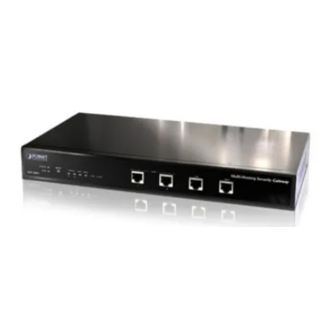
MH-2001 Multi-Homing Security Gateway User’s Manual - Port definition Port Description WAN1, WAN2 Connect to your xDSL/Cable modem or other Internet connection devices Connect to your local PC, switch or other local network device Connect to your server or other network device 1.4 MH-2001 Rear Panel... -
Page 10: Specification
MH-2001 Multi-Homing Security Gateway User’s Manual 1.5 Specification Product Multi-Homing Security Gateway Model MH-2001 Hardware Ethernet 1 x 10/100Mbps RJ-45 2 x 10/100Mbps RJ-45 1 x 10/100Mbps RJ-45 Button Reset button for reset to factory default setting Software Management DMZ_NAT, DMZ_Transparent, NAT... -
Page 11: Chapter 2: Hardware Installation
- Electrical Requirements MH-2001 is a power-required device, which means, it will not work until it is powered. If your network PCs will need to transmit data all the time, please consider use an UPS (Uninterrupted Power Supply) for your MH-2001. -
Page 12: Operation Mode
MH-2001 DMZ port supports three operation modes, Disable, NAT and Transparent. In Disable mode, the DMZ port is not active. In transparent mode, MH-2001 works as proxy with forward DMZ packet to WAN and forward WAN packet to DMZ. The DMZ and WAN side IP addresses are in the same subnet. In NAT mode, DMZ side user will share one public IP address of WAN port to make Internet connection. -
Page 13: Nat Mode Connecting Example
MH-2001 Multi-Homing Security Gateway User’s Manual 2.2.2 NAT Mode Connecting Example DMZ and WAN1 IP addresses are on the different subnet. This provides higher security level then transparent mode. - 7 -... -
Page 14: Chapter 3: Getting Started
3.1 Web Configuration STEP 1: Connect the Administrator’s PC and the LAN port of MH-2001 to a hub or switch. Make sure there is a link light on the hub/switch for both connections. MH-2001 has an embedded web server used for management and configuration. -
Page 15: Configure Wan 1 Interface
MH-2001 Multi-Homing Security Gateway User’s Manual 3.2 Configure WAN 1 interface After entering the username and password, MH-2001 WebUI screen will display. Select the Interface tab on the left menu. Click on WAN from the sub-function list, and a sub-function list will be displayed. - Page 16 Max. Upstream/Downstream Bandwidth: The bandwidth provided by ISP. Ping: Select this to allow the WAN network to ping the IP Address of MH-2001 This will allow people from the Internet to be able to ping MH-2001 WAN IP. If set to enable, the device will respond to echo request packets from the WAN network.
-
Page 17: Configure Wan 2 Interface
MH-2001 Multi-Homing Security Gateway User’s Manual HTTP: Select this to allow the device WebUI to be accessed from the WAN network. This will allow the WebUI to be configured from a user on the Internet. Keep in mind that the device always requires a username and password to enter the WebUI. - Page 18 Please make sure that all the computers that are connected to the LAN port have their Default Gateway IP Address set to MH-2001’s LAN IP Address (i.e. 192.168.1.1). At this point, all the computers on the LAN network should gain access to the Internet immediately. If MH-2001 filter function is required, please refer to the Policy section in chapter 7.
-
Page 19: Chapter 4: System
2. Back up all MH-2001 settings into local files; 3. Set up alerts for Hackers invasion. “System” is the managing of settings such as the privileges of packets that pass through MH-2001 and monitoring controls. Administrators may manage, monitor, and configure MH-2001 settings. All configurations are “read-only”... - Page 20 MH-2001 Multi-Homing Security Gateway User’s Manual clicking New Sub Admin . Sub Admin have only read and monitor privilege and cannot change any system setting value. Configure: Click Modify to change the “Sub-Administrator’s” password or click Remove to delete a “Sub Administrator.”...
- Page 21 MH-2001 Multi-Homing Security Gateway User’s Manual Removing a Sub Administrator Step 1. In the Administration table, locate the Administrator name you want to edit, and click on the Remove option in the Configure field. Step 2. The Remove confirmation pop-up box will appear. Click OK to remove that Sub Admin or click Cancel to cancel.
-
Page 22: Permitted Ips
To make Permitted IPs be effective, it must cancel the Ping and HTTP selection in the WebUI of MH-2001 that Administrator enter. (LAN, WAN, or DMZ Interface) Before canceling the HTTP selection of Interface, must set up the Permitted IPs first, otherwise, it would cause the situation of cannot enter WebUI by appointed Interface. -
Page 23: Software Update
MH-2001 Multi-Homing Security Gateway User’s Manual 4.1.3 Software Update Under Software Update, the admin may update the device’s software with newer software. You may acquire the current version number of software in Version Number. Administrators may visit distributor’s web site to download the latest version and save it in server’s hard disc. -
Page 24: Configure
Date/Time, Multiple Subnet, Route Table, DHCP, Dynamic DNS, Hosts Table, and Language settings. 4.2.1 Setting The Administrator may use this function to backup, restore MH-2001 configurations or restore MH-2001 back to default factory settings. You can also set general setting like device’s name, E-mail setting and HTTP port on it. - Page 25 Importing MH-2001 settings Under Backup/Restore Configuration, click on the Browse button next to Import System Settings. When the Choose File pop-up window appears, select the file which contains the saved MH-2001 Settings, then click OK. Click OK to import the file into MH-2001 or click Cancel to cancel importing.
- Page 26 Enabling E-mail Alert Notification Step 1. Select Enable E-mail Alert Notification under E-Mail Settings. This function will enable the MH-2001 to send e-mail alerts to the System Administrator when the network is being attacked by hackers or when emergency conditions occur.
- Page 27 MH-2001 Multi-Homing Security Gateway User’s Manual Click on Mail Test to test if E-mail Address 1 and E-mail Address 2 can receive the Alert Notification correctly. Web Management (WAN Interface) The administrator can change the port number used by HTTP port anytime. (Remote WebUI management) After HTTP port has changed, if the administrator want to enter WebUI from WAN, will have to change the port number of browser.
- Page 28 RIP can connect automatically. You can choose to enable LAN, WAN1, WAN2 or DMZ interface to allow RIP protocol supporting. Routing information update timer: MH-2001 will send out the RIP protocol in a period of time to update the routing table, the default timer is 30 seconds.
- Page 29 SIP protocol pass-through Select this option to the device’s SIP protocol pass-through. Once this function is enabled, the SIP packets will be allowed to pass-through via MH-2001. To-Appliance Packets Log Select this option to the device’s To-Appliance Packets Log. Once this function is enabled, every packet to this appliance will be recorded for system administrator to trace.
-
Page 30: Date/Time
MH-2001 Multi-Homing Security Gateway User’s Manual System Reboot Once this function is enabled, MH-2001 will be rebooted. Click Reboot. The confirmation pop-up box will appear. Click OK to restart MH-2001 or click Cancel to discard changes 4.2.2 Date/Time Synchronizing the MH-2001 with the System Clock Administrator can configure MH-2001’s date and time by either syncing to an Internet Network Time Server... -
Page 31: Multiple Subnet
MH-2001 Multi-Homing Security Gateway User’s Manual The value of Set Offset From GMT and Server IP / Name can be looking for from Assist. 4.2.3 Multiple Subnet NAT mode Multiple Subnet allows local port to set multiple subnet works and connect with the internet through different WAN 1 IP Addresses. - Page 32 MH-2001 Multi-Homing Security Gateway User’s Manual Multiple Subnet settings Click Multiple Subnet under the System/Configure menu to enter Multiple Subnet window. Multiple Subnet functions: WAN Interface IP / Forwarding Mode: Display WAN Port IP Address and Forwarding Mode. Alias IP of Interface / Netmask: Local Interface IP Address and subnet Mask.
- Page 33 MH-2001 Multi-Homing Security Gateway User’s Manual For example, the leased line of a company applies several real IP Addresses 168.85.88.0/24 and the company is divided into R&D, Customer Service, Sales, Procurement, and Accounting Department. The company can distinguish each department by different sub-network for the purpose of convenient management.
-
Page 34: Route Table
MH-2001 Multi-Homing Security Gateway User’s Manual 4.2.4 Route Table In this section, the Administrator can add static routes for the networks. Entering the Route Table screen Click Route Table under the System/Configure menu and the Route Table window will appear, in which current route settings are shown. -
Page 35: Dhcp
MH-2001 Multi-Homing Security Gateway User’s Manual 4.2.5 DHCP In this section, the Administrator can configure DHCP (Dynamic Host Configuration Protocol) settings for the LAN and DMZ network. Entering the DHCP window Click DHCP under the System/Configure menu. The DHCP window appears in which current DHCP settings are shown on the screen. -
Page 36: Dynamic Dns
MH-2001 Multi-Homing Security Gateway User’s Manual Enabling DHCP Support Step 1. In the DHCP window, click Enable DHCP Support. Domain Name: The Administrator may enter the name of the LAN network domain if preferred. Automatically Get DNS: Check this box to automatically detect DNS server. - Page 37 MH-2001 Multi-Homing Security Gateway User’s Manual The icons in Dynamic DNS window: ! : Update Status Chart Meaning Update successfully Incorr ect usernam e or Connecting to server Unknown error password Domain name: Your host domain name. WAN IP Address: IP Address of the WAN port.
-
Page 38: Host Table
To use Host Table, the user PC’s first DNS Server must be the same as the LAN Port or DMZ Port IP of MH-2001. That is, the default gateway. 2.8 Language dministrator can configure MH-2001 to select the Language version Step 1. Select the Languag e version (English Version, Traditional Chinese Version or Simplified Chinese Version). -
Page 39: Logout
MH-2001 Multi-Homing Security Gateway User’s Manual 4.3 Logout STEP 1﹒ Click Logout in System to protect the system while Administrator is away. Confirm Logout WebUI STEP 2﹒ Click OK and the logout message will appear in WebUI. Logout WebUI Message... -
Page 40: Chapter 5: Interface
The default IP address is 192.168.1.1. If the new LAN IP Address is not 192.168.1.1, the Administrator needs to set the IP Address on the computer to be on the same subnet as MH-2001 and restart the System to make the new IP address effective. -
Page 41: Wan
Auto: The MH-2001 will adjust the WAN 1/2 utility rate automatically according to the downstream/upstream of WAN. (For users who are using various download bandwidth) Round-Robin: The MH-2001 distributes the WAN 1/2 download bandwidth 1:1, in other words, it selects the agent by order. (For users who are using same download bandwidths) By Traffic: The MH-2001 distributes the WAN 1/2 download bandwidth by accumulative traffic. - Page 42 DNS Service Connection test is used for MH-2001 to detect if the WAN can connect or not. So the Alive Indicator Site IP, DNS Server IP Address, or Domain Name must be able to use permanently. Or it will cause judgmental mistakes of the device.
- Page 43 MH-2001 Multi-Homing Security Gateway User’s Manual STEP 3﹒Select the Connecting way: PPPoE (ADSL User): 1. Select PPPoE 2. Enter User Name as an account 3. Enter Password as the password 4. Select Dynamic or Fixed in IP Address provided by ISP. If you select Fixed, please enter IP Address, Netmask, and Default Gateway.
- Page 44 MH-2001 Multi-Homing Security Gateway User’s Manual Dynamic IP Address (Cable Modem User) : 1. Select Dynamic IP Address (Cable Modem User) 2. Click Renew in the right side of IP Address and then can obtain IP automatically. 3. If the MAC Address is required for ISP then click on Clone MAC Address to obtain MAC IP automatically.
- Page 45 6. Click OK Static IP Address Connection When selecting Ping and HTTP on WAN network Interface, users will be able to ping the MH-2001 and enter the WebUI WAN network. It may influence network security. The suggestion is to Cancel Ping and HTTP after all the settings have finished.
-
Page 46: Dmz
Netmask: This will be the subnet mask of the DMZ network. Ping: Select this to allow the DMZ network to ping the IP Address of MH-2001. If set to enable, the device will respond to echo request packets from the DMZ network. - Page 47 MH-2001 Multi-Homing Security Gateway User’s Manual Setting DMZ Interface Address (Transparent Mode) STEP 1﹒Select DMZ Interface STEP 2﹒Select Transparent Mode in DMZ Interface Select DMZ_Transparent in DMZ Interface STEP 3﹒Select Ping and HTTP STEP 4﹒Click OK Setting DMZ Interface Address (Transparent Mode) WebUI In WAN, the connecting way must be Static IP Address and can choose Transparent Mode in DMZ.
-
Page 48: Chapter 6: Policy Object
Chapter 6: Policy Object 6.1 Address MH-2001 allows the Administrator to set addresses of the LAN network, LAN network group, WAN network, WAN group, DMZ network and DMZ group. These settings are to be used for policy editing. What is the Address Table? An IP address in the Address Table can be an address of a computer or a sub network. - Page 49 MH-2001 to fill out the user’s MAC Address automatically. In LAN of Address function, the MH-2001 has an default Inside Any address setting represents the whole LAN network automatically. Others like WAN, DMZ also have the Outside Any and DMZ Any default address setting to represent the whole subnet.
-
Page 50: Lan Group
MH-2001 Multi-Homing Security Gateway User’s Manual 6.1.2 LAN Group Entering the LAN Group window The LAN Addresses may be combined together to become a group. Step 1. Click LAN Group under the Address menu to enter the LAN Group window. The current setting information for the LAN network group appears on the screen. -
Page 51: Wan
MH-2001 Multi-Homing Security Gateway User’s Manual 6.1.3 WAN Entering the WAN window Step 1. Click WAN under the Address menu to enter the WAN window. The current setting information, such as the name of the WAN network, IP and Netmask addresses will show on the screen. -
Page 52: Wan Group
MH-2001 Multi-Homing Security Gateway User’s Manual message – . In this case, you are not allowed to modify or remove the setting. You have to remove the setting in Policy or WAN Group, and then you are allowed to configure the WAN address. -
Page 53: Dmz
MH-2001 Multi-Homing Security Gateway User’s Manual Adding an WAN Group Step 2. In the WAN Group window, click the New Entry button and the Add New Address Group window will appear. Step 3. In the Add New Address Group window the following fields will appear: Name: Enter the name of the new group. - Page 54 MH-2001 Multi-Homing Security Gateway User’s Manual Definition Name: Name of DMZ network address. IP: IP address of DMZ network Netmask: subnet mask of DMZ network. MAC Address: MAC address corresponded with DMZ IP address. Configure: You can configure the settings in DMZ network. Click Modify to change the parameters in DMZ network.
-
Page 55: Dmz Group
MH-2001 Multi-Homing Security Gateway User’s Manual 6.1.6 DMZ Group Entering the DMZ Group window Click DMZ Group under the Address menu to enter the DMZ window. The current settings information for the DMZ group appears on the screen. Definitions: Name: Name of the DMZ group. - Page 56 MH-2001 Multi-Homing Security Gateway User’s Manual - 50 -...
-
Page 57: Example1
MH-2001 Multi-Homing Security Gateway User’s Manual 6.1.7 Example1 Under DHCP situation, assign the specific IP to static users and restrict them to access FTP net service only through policy STEP 1﹒Select LAN in Address and enter the following settings: Click New Entry button Name: Enter Rayearth IP Address: Enter 192.168.3.2... - Page 58 MH-2001 Multi-Homing Security Gateway User’s Manual STEP 2﹒Adding the following setting in Outgoing Policy: Add a Policy of Restricting the Specific IP to Access to Internet STEP 3﹒Complete assigning the specific IP to static users in Outgoing Policy and restrict them to access...
-
Page 59: Example2
MH-2001 Multi-Homing Security Gateway User’s Manual 6.1.8 Example2 Setup a policy that only allows partial users to connect with specific IP (External Specific IP) STEP 1 . Setting several LAN network Address. Setting Several LAN Network Address STEP 2 . Enter the following settings in LAN Group of Address:... - Page 60 MH-2001 Multi-Homing Security Gateway User’s Manual Complete Adding LAN Address Group The setting mode of WAN Group and DMZ Group of Address are the same as LAN Group. STEP 3 . Enter the following settings in WAN of Address function:...
- Page 61 MH-2001 Multi-Homing Security Gateway User’s Manual STEP 4 . To exercise STEP1~3 in Policy To Exercise Address Setting in Policy Complete the Policy Setting The Address function really take effect only if use with Policy. - 55 -...
-
Page 62: Service
TCP and UDP protocols support varieties of services, and each service consists of a TCP Port or UDP port number, such as TELNET(23), SMTP(21), POP3(110),etc. MH-2001 defines two services: pre-defined service and custom service. The common-use services like TCP and UDP are defined in the pre-defined service and cannot be modified or removed. -
Page 63: Custom
MH-2001 Multi-Homing Security Gateway User’s Manual Icons and Descriptions Figure Description Any Service TCP services, e.g. TCP, FTP, FINGER, HTTP, HTTPS, IMAP, SMTP, POP3, ANY, AOL, BGP, GOPHER, Inter Locator, IRC, L2TP, LDAP, NetMeeting, NNTP, PPTP, Real Media, RLOGIN, SSH, TCP ANY, TELNET, VDO Live, WAIS, WINFRAME, X-WINDOWS, MSN, etc. -
Page 64: Group
MH-2001 Multi-Homing Security Gateway User’s Manual If one of the Services has been added to Policy or Group, Configure column will show the message – . In this case, you are not allowed to modify or remove the settings. You have to remove the setting in Policy or Group window, and then you are allowed to configure the settings. - Page 65 MH-2001 Multi-Homing Security Gateway User’s Manual Definitions: Group name: The Group name of the defined Service. Service: The Service item of the Group. Configure: Configure the settings of Group. Click Modify to change the parameters of the Group. Click Remove to delete the Group.
-
Page 66: Schedule
Administrator is allowing MH-2001 policies to be used at those designated times only. Any activities outside of the scheduled time slot will not follow MH-2001 policies therefore will likely not be permitted to pass through MH-2001. The Administrator can configure the start time and stop time, as well as creating 2 different time periods in a day. -
Page 67: Qos
QoS Priority: To configure the priority of distributing Upstream/Downstream and unused bandwidth. MH-2001 configures the bandwidth by different QoS, and selects the suitable QoS through Policy to control and efficiently distribute bandwidth. MH-2001 also makes it convenient for the administrator to make the Bandwidth reach the best Utility. - Page 68 MH-2001 Multi-Homing Security Gateway User’s Manual The Flow After Using QoS (Max. Bandwidth: 400Kbps, Guaranteed Bandwidth: 200Kbps) Configuration of QoS Click on Setting under QoS menu and the QoS window will appear. Definitions: Name: The name of the QoS you want to configure.
-
Page 69: Authentication
By configuring the Authentication, you can control the user’s connection authority. The user has to pass the authentication to access to Internet. The MH-2001 appliance provided 3 authentication modes. The User and User Group built in; others are RADIUS and POP3 self-built Authentication Server. The MIS engineer can use the 4 modes, to manage the authentication. -
Page 70: Auth User
MH-2001 Multi-Homing Security Gateway User’s Manual Definitions: Authentication Port: The internal users have to pass the authentication to access to the Internet when enable MH-2001. Re-Login if Idle: When the internal user access to Internet, can setup the idle time after passing authentication. - Page 71 MH-2001 Multi-Homing Security Gateway User’s Manual Auth-User Name: enter the username of new Authentication. Password: enter a password for the new Authentication. Confirm Password: enter the password again. Step 3. Click OK to add the user or click Cancel to cancel the setting Step 4.
- Page 72 MH-2001 Multi-Homing Security Gateway User’s Manual Step 5. When the user connect to external network by Authentication, the following page will be displayed. Enter the User Name and Password for authentication. Step 6. Authentication success, it will pop-up a window that you can logout and you can access to internet.
-
Page 73: Auth User Group
MH-2001 Multi-Homing Security Gateway User’s Manual 6.5.3 Auth User Group Entering the Auth User Group window Click Authentication in the menu bar on the left hand side of the window and click Auth Group under it. A window will appear with a table displaying current Auth User Group settings by the Administrator. - Page 74 MH-2001 Multi-Homing Security Gateway User’s Manual STEP 2 . Add a policy in Outgoing Policy and input the Address and Authentication of STEP 1 Auth-User Policy Setting Complete the Policy Setting of Auth-User - 68 -...
- Page 75 MH-2001 Multi-Homing Security Gateway User’s Manual STEP 3 . When user is going to access to Internet through browser, the authentication UI will appear in Browser. After entering the correct user name and password, click OK to access to Internet.
-
Page 76: Radius Server
MH-2001 Multi-Homing Security Gateway User’s Manual 6.5.4 Radius Server To plan the users connect to the WAN through the authenticaton in policy .To use the WAN RADIUS server (Windows 2003 Server built-in authentication). ※ Windows 2003 RADIUS Server Deployment STEP 1 . Click Start... - Page 77 MH-2001 Multi-Homing Security Gateway User’s Manual STEP 3 . Select Internet Authentication Service. Add new network authentication service components - 71 -...
- Page 78 MH-2001 Multi-Homing Security Gateway User’s Manual STEP 4 . Click Start Control Panel Administrative Tools, select Network Authentication Service. Select network authentication service - 72 -...
- Page 79 MH-2001 Multi-Homing Security Gateway User’s Manual STEP 5 . Right click RADIUS Clients New RADIUS Client. Add new RADIUS client - 73 -...
- Page 80 MH-2001 Multi-Homing Security Gateway User’s Manual STEP 6 . Enter the Name and Client Address (It is the same as MH-2001 IP Address). Add New RADIUS client name and IP address setting - 74 -...
- Page 81 MH-2001 Multi-Homing Security Gateway User’s Manual STEP 7 . Select RADISU Standard; enter the Shared secret and Confirm Shared secret. (It must be the same setting as RADIUS in MH-2001. Add new RADIUS client-vendor and shared secret - 75 -...
- Page 82 MH-2001 Multi-Homing Security Gateway User’s Manual STEP 8 . Right click on Remote Access Policies New Remote Access Policy. Add new romote access policies - 76 -...
- Page 83 MH-2001 Multi-Homing Security Gateway User’s Manual STEP 9 . Select Use the wizard to set up a typical policy for a common scenario, and enter the Policy name. Add new romote access policies and policy name - 77 -...
- Page 84 MH-2001 Multi-Homing Security Gateway User’s Manual STEP 10 . Select Ethernet. The way to add new remote access policy - 78 -...
- Page 85 MH-2001 Multi-Homing Security Gateway User’s Manual STEP 11 . Select User. Add new remote access policy user and group - 79 -...
- Page 86 MH-2001 Multi-Homing Security Gateway User’s Manual Select MD5-Challenge. STEP 12 . The authentication of add new remote access policy - 80 -...
- Page 87 MH-2001 Multi-Homing Security Gateway User’s Manual STEP 13 . Right click on the Radius Properties. The network authentication service setting - 81 -...
- Page 88 MH-2001 Multi-Homing Security Gateway User’s Manual STEP 14 . Select Grant remote access permission, and Remove the original setting, then click Add. The RADIUS properties settings - 82 -...
- Page 89 MH-2001 Multi-Homing Security Gateway User’s Manual STEP 15 . Add Service-Type. Add new RADIUS properties attribute - 83 -...
- Page 90 MH-2001 Multi-Homing Security Gateway User’s Manual STEP 16 . Add Authenticate Only from the left side. Add RADIUS properties service-type - 84 -...
- Page 91 MH-2001 Multi-Homing Security Gateway User’s Manual STEP 17 . Click Edit Profile, select Authentication, and check Unencrypted authentication (PAP, SPAP). Edit RADIUS service-type dial-in property - 85 -...
- Page 92 MH-2001 Multi-Homing Security Gateway User’s Manual STEP 18 . Add Auth User, click Start Setting Control Panel Administrative Tools, select Computer Management. Enter computer management - 86 -...
- Page 93 MH-2001 Multi-Homing Security Gateway User’s Manual STEP 19 . Right click on Users, select New User. Add new user STEP 20 . Complete the Windows 2003 RADIUS Server Settings. - 87 -...
- Page 94 MH-2001 Multi-Homing Security Gateway User’s Manual STEP 21 . In Authentication RADIUS function, enter IP, Port and Shared Secret. (The setting must be the same as RADIUS server). The RADIUS server setting STEP 22 . In Authentication User Group, add new Radius User.
- Page 95 STEP 24 . When the users connect to the network via the browser, it will show the authentication window. Enter the user name and password, click OK, and then link to the network through the MH-2001. Link to the network through the authentication window...
-
Page 96: Pop3
MH-2001 Multi-Homing Security Gateway User’s Manual 6.5.5 POP3 To plan the users connect to the WAN through the authentication by policy. (To use the WAN POP3 server authentication) STEP 1 . In Authentication POP3, add the new setting as following. - Page 97 STEP 4 . When the users want to connect to the network via browser, it will show the authentication window. Enter the user name and password, click OK then link to the network through the MH-2001 appliance. Link to the network through the authentication window...
-
Page 98: Content Blocking
Step 1. Click on URL under the Content Blocking menu bar and the screen will display as below.. Definition: URL String: The domain name that is blocked to enter by MH-2001. Configure: To change the settings of URL Blocking, click Modify to change the parameters; click Remove to delete the settings. - Page 99 MH-2001 Multi-Homing Security Gateway User’s Manual Step 3. Click OK to add the policy. Click Cancel to discard changes. Step 4. After finishing Content Filtering setting, you must enable it at Outgoing Policy, or Content Filtering will not be workable.
-
Page 100: Script Blocking
MH-2001 Multi-Homing Security Gateway User’s Manual 6.6.2 Script Blocking To let Popup, ActiveX, Java, or Cookies in or keep them out. Step 1. Click Content Blocking in the menu. Step 2. Script Blocking detective functions. Popup: Prevent pop-up boxes from appearing. -
Page 101: Download Blocking
MH-2001 Multi-Homing Security Gateway User’s Manual 6.6.3 Download Blocking Step 1. Click Content Blocking in the menu. Step 2. Select Download Blocking and configure the setting. All Types Blocking: To block all types of the files downloading from web page. -
Page 102: Upload Blocking
MH-2001 Multi-Homing Security Gateway User’s Manual 6.6.4 Upload Blocking Step 1. Click Content Blocking in the menu. Step 2. Select Upload Blocking and configure the setting. All Types Blocking: To block all types of the files uploading to Internet. Extensions Blocking: To block specific extensions name of the files to Internet. -
Page 103: Im/P2P Blocking
MH-2001 Multi-Homing Security Gateway User’s Manual 6.7 IM/P2P Blocking Restrict the Internal Users to access to the file on Internet by IM and P2P software. Step 1. Click IM/P2P Blocking in the menu. Step 2. Select Setting and configure the setting. -
Page 104: Virtual Server
IP address. MH-2001’s Virtual Server can solve this problem. A virtual server has set the real IP address of MH-2001’s WAN network interface to be the Virtual Server IP. Through the virtual server feature, MH-2001 translates the virtual server’s IP address into the private IP address of physical server in the LAN network. -
Page 105: Mapped Ip
MH-2001 Multi-Homing Security Gateway User’s Manual 6.8.1 Mapped IP Internal private IP addresses are translated through NAT (Network Address Translation). If a server is located in the LAN network, it has a private IP address, and outside users cannot connect directly to LAN servers’... - Page 106 MH-2001 Multi-Homing Security Gateway User’s Manual Step 4. Group the services (DNS, FTP, HTTP, POP3, SMTP…) that provided and used by server in Service function. And add a new service group for server to send mails at the same time.
- Page 107 MH-2001 Multi-Homing Security Gateway User’s Manual Step 6. Add a policy that includes STEP2 and 4 in Outgoing Policy. It makes the server to send e-mail to external mail server by mail service. Complete the Outgoing Policy Step 7. Complete the setting of providing several services by mapped IP.
-
Page 108: Virtual Server 1- 4
MH-2001 Multi-Homing Security Gateway User’s Manual 6.8.2 Virtual Server 1- 4 Virtual server is a one-to-many mapping technique, which maps a real IP address from the WAN interface to private IP addresses of the LAN network. This function provides services or applications defined in the Service menu to enter into the LAN network. - Page 109 MH-2001 Multi-Homing Security Gateway User’s Manual Virtual Server Configuration WebUI Step 4. Add a new policy in Incoming Policy, which includes the virtual server, set by STEP2 and 3. Virtual Server Configuration WebUI In this example, the external users must change its port number to 8080 before entering the Website that set by the Web server.
-
Page 110: Vpn
MH-2001 Multi-Homing Security Gateway User’s Manual 6.9 VPN The MH-2001 adopts VPN to set up safe and private network service. And combine the remote Authentication system in order to integrate the remote network and PC of the enterprise. Also provide the enterprise and remote users a safe encryption way to have best efficiency and encryption when delivering data. - Page 111 MH-2001 Multi-Homing Security Gateway User’s Manual ESP (Encapsulating Security Payload): One of the IPSec standards that provides for the confidentiality of data packets. DES (Data Encryption Standard): The Data Encryption Standard developed by IBM in 1977 is a 64-bit block encryption block cipher using a 56-bit key.
- Page 112 MH-2001 Multi-Homing Security Gateway User’s Manual Define the required fields of IPSec Function To display the VPN connection status via icon。 Chart Meaning Not be applied Disconnect Connecting Name: The VPN name to identify the IPSec Autokey definition. The name must be the only one and cannot be repeated.
- Page 113 MH-2001 Multi-Homing Security Gateway User’s Manual Define the required fields of PPTP Server Function PPTP Server: To select Enable or Disable Client IP Range: Setting the IP addresses range for PPTP Client connection To display the VPN connection status via icon。...
- Page 114 MH-2001 Multi-Homing Security Gateway User’s Manual Define the required fields of PPTP Client Function To display the VPN connection status via icon。 Chart Meaning Not be applied Disconnect Connecting User Name: Displays the PPTP Client user’s name when connecting to PPTP Server.
- Page 115 MH-2001 Multi-Homing Security Gateway User’s Manual Define the required fields of Tunnel Function To display the VPN connection status via icon。 Chart Meaning Not be applied Disconnect Connecting Name: The VPN name to identify the VPN tunnel definition. The name must be the only one and cannot be repeated.
- Page 116 To access the static subnet resources via the IPSec VPN Autokey connection between two MH-2001 appliances. Example.2 IPSec The way to set the MH-2001 appliance IPSec VPN Autokey connection in Windows 2000. Example.3 IPSec The way to set the IPSec VPN connection between two Autokey MH-2001 appliances.
-
Page 117: Example.1
WAN IP: 61.11.11.11 LAN IP: 192.168.10.X Company B WAN IP: 211.22.22.22 LAN IP: 192.168.20.X Multiple Subnet: 192.168.85.X This example takes two MH-2001 as work platform. Suppose Company A 192.168.10.100 create a VPN connection with Company B 192.168.85.100 for downloading the sharing file. - Page 118 The Default Gateway of Company A is the MH-2001 LAN IP 192.168.10.1. Follow the steps below: STEP 1 . Enter the default IP of Gateway of Company A’s MH-2001, 192.168.10.1 and select IPSec Autokey in VPN. Click New Entry. IPSec Autokey WebUI STEP 2 .
- Page 119 MH-2001 Multi-Homing Security Gateway User’s Manual STEP 3 . Select Remote Gateway-Fixed IP or Domain Name In To Destination list and enter the IP Address. IPSec To Destination Setting STEP 4 . Select Preshare in Authentication Method and enter the Preshared Key (max: 100 bits) IPSec Authentication Method Setting STEP 5 .
- Page 120 MH-2001 Multi-Homing Security Gateway User’s Manual STEP 6 . You can choose Data Encryption + Authentication or Authentication Only to communicate in IPSec Algorithm list: ENC Algorithm: 3DES/DES/AES/NULL AUTH Algorithm: MD5/SHA1 Here we select 3DES for ENC Algorithm and MD5 for AUTH Algorithm to make sure the encapsulation...
- Page 121 MH-2001 Multi-Homing Security Gateway User’s Manual STEP 9 . Enter the following setting in Tunnel of VPN function: Enter a specific Tunnel Name. From Source: Select LAN From Source Subnet / Mask: Enter 192.168.10.0 / 255.255.255.0. To Destination: Select To Destination Subnet / Mask.
- Page 122 MH-2001 Multi-Homing Security Gateway User’s Manual STEP 10 . Enter the following setting in Outgoing Policy: Tunnel: Select IPSec_VPN_Tunnel. Click OK. Setting the VPN Tunnel Outgoing Policy Complete the VPN Tunnel Outgoing Policy Setting - 116 -...
- Page 123 MH-2001 Multi-Homing Security Gateway User’s Manual STEP 11 . Enter the following setting in Incoming Policy: Tunnel: Select IPSec_VPN_Tunnel. Click OK. Setting the VPN Tunnel Incoming Policy Complete the VPN Tunnel Incoming Policy Setting - 117 -...
- Page 124 STEP 12 . Enter the following setting in Multiple Subnet of System Configure function: Multiple Subnet Setting STEP 13 . Enter the default IP of Gateway of Company B’s MH-2001, 192.168.20.1 and select IPSec Autokey in VPN. Click New Entry.
- Page 125 MH-2001 Multi-Homing Security Gateway User’s Manual STEP 15 . Select Remote Gateway-Fixed IP or Domain Name In To Destination list and enter the IP Address. IPSec To Destination Setting STEP 16 . Select Preshare in Authentication Method and enter the Preshared Key. (The maximum Preshared Key is 100 bytes).
- Page 126 MH-2001 Multi-Homing Security Gateway User’s Manual STEP 18 . You can choose Data Encryption + Authentication or Authentication Only to communicate in IPSec Algorithm list: ENC Algorithm: 3DES/DES/AES/NULL AUTH Algorithm: MD5/SHA1 Here we select 3DES for ENC Algorithm and MD5 for AUTH Algorithm to make sure the encapsulation way for data transmission.
- Page 127 MH-2001 Multi-Homing Security Gateway User’s Manual STEP 21 . Enter the following setting in Tunnel of VPN function: Enter a specific Tunnel Name. From Source: Select LAN From Source Subnet / Mask: Enter 192.168.85.0 / 255.255.255.0. To Destination: Select To Destination Subnet / Mask.
- Page 128 MH-2001 Multi-Homing Security Gateway User’s Manual STEP 22 . Enter the following setting in Outgoing Policy: Tunnel: Select IPSec_VPN_Tunnel. Click OK. Setting the VPN Tunnel Outgoing Policy Complete the VPN Tunnel Outgoing Policy Setting - 122 -...
- Page 129 MH-2001 Multi-Homing Security Gateway User’s Manual STEP 23 . Enter the following setting in Incoming Policy: Tunnel: Select IPSec_VPN_Tunnel. Click OK. Setting the VPN Tunnel Incoming Policy Complete the VPN Tunnel Incoming Policy Setting STEP 24 . Complete IPSec VPN Connection.
-
Page 130: Example.2
LAN IP: 192.168.10.X Company B : The PC with Windows 2000 inside. WAN IP: 211.22.22.22 We use the MH-2001 and Windows 2000 VPN-IPsec to be the platform. On the other hand, we assume that B Company 211.22.22.22 want to build the VPN to A Company 192.168.10.100, in order to download the shared document. - Page 131 MH-2001 Multi-Homing Security Gateway User’s Manual The A Company‘s default gateway is the LAN IP 192.168.10.1 in the MH-2001. Add the following settings: STEP 1 . Enter the A Company’s MH-2001 default IP 192.168.10.1. Click VPN IPSec Autokey Entry. IPSec Autokey STEP 2 .
- Page 132 MH-2001 Multi-Homing Security Gateway User’s Manual STEP 5 . In Encapsulation select ISAKMP Algorithm. Select the needed algorithm as both sides start the connection. In ENC Algorithm (3DES/DES/AES), select 3DES. In AUTH Algorithm (MD5/SHA1), select MD5. In Group (GROUP 1, 2, 5), select GROUP 2. The both sides need to select the same group.
- Page 133 MH-2001 Multi-Homing Security Gateway User’s Manual STEP 7 . In Perfect Forward Secrecy (NO-PFS/ GROUP 1, 2, 5), select GROUP 1. In ISAKMP Lifetime, enter 3600 seconds. In IPSec Lifetime, enter 28800 seconds. In Mode, select main mode. The IPSec Perfect Forward Secrecy setting STEP 8 .
- Page 134 MH-2001 Multi-Homing Security Gateway User’s Manual STEP 9 . In VPN Tunnel , add the following settings: Name, enter the Tunnel Name. From Source, select LAN. From Source Subnet / Mask, enter Source LAN IP192.168.10.0 (A Company), and Mask 255.255.255.0.
- Page 135 MH-2001 Multi-Homing Security Gateway User’s Manual STEP 10 . In Policy Outgoing, add the following settings: Tunnel, select IPSec_VPN_Tunnel. Click OK. Set the outgoing policy setting included the VPN Tunnel Complete the outgoing policy setting included the VPN Tunnel - 129 -...
- Page 136 MH-2001 Multi-Homing Security Gateway User’s Manual STEP 11 . In Policy Incoming, add the following settings: Tunnel, select IPSec_VPN_Tunnel. Click OK. Set the incoming policy setting included the VPN Tunnel Complete the incoming policy setting included the VPN Tunnel - 130 -...
- Page 137 MH-2001 Multi-Homing Security Gateway User’s Manual The B Company’s real IP is 211.22.22.22, add the following settings: STEP 12 . Click Start Run in Windows 2000 Start the IPSec VPN setting in Windows 2000 - 131 -...
- Page 138 MH-2001 Multi-Homing Security Gateway User’s Manual STEP 13 . In Run Open column, enter mmc. To startup the Windows 2000 IPSec VPN setting STEP 14 . In Console 1 Console Add/Remove Snap-in. Add / Remove Snap-in . - 132 -...
- Page 139 MH-2001 Multi-Homing Security Gateway User’s Manual STEP 15 . In Add / Remove Snap-in, click Add. In Add Standalone Snap-in, add IP Security Policy Management. Add IP Security Policy Management - 133 -...
- Page 140 MH-2001 Multi-Homing Security Gateway User’s Manual STEP 16 . Select Local Computer, click Finish. Select the type of IP Security Policy Management - 134 -...
- Page 141 MH-2001 Multi-Homing Security Gateway User’s Manual STEP 17 . Complete to set the IP Security Policy Management. Complete to set the IP Security Policy Management - 135 -...
- Page 142 MH-2001 Multi-Homing Security Gateway User’s Manual STEP 18 . Right click on the IP Security Policies on Local Machine, and select Create IP Security Policy. Create IP Security Policy - 136 -...
- Page 143 MH-2001 Multi-Homing Security Gateway User’s Manual STEP 19 . Click Next. Open IP Security Policy Wizard - 137 -...
- Page 144 MH-2001 Multi-Homing Security Gateway User’s Manual STEP 20 . Enter the VPN Name and Description, and click Next. Set the VPN name and description - 138 -...
- Page 145 MH-2001 Multi-Homing Security Gateway User’s Manual STEP 21 . Disable to Activate the default response rule, and click Next. Disable to activate the default response rule - 139 -...
- Page 146 MH-2001 Multi-Homing Security Gateway User’s Manual STEP 22 . In IP Security Policy Wizard, select Edit properties, click Finish. Complete the IP Security Policy Wizard settings - 140 -...
- Page 147 MH-2001 Multi-Homing Security Gateway User’s Manual STEP 23 . In VPN_B Properties, do not select Use Add Wizard, and click Add. VPN_B Properties - 141 -...
- Page 148 MH-2001 Multi-Homing Security Gateway User’s Manual STEP 24 . In New Rule Properties, Click Add. New Rule Properties - 142 -...
- Page 149 MH-2001 Multi-Homing Security Gateway User’s Manual STEP 25 . In IP Filter List, do not select Use Add Wizard. Modify the Name into VPN_B WAN TO LAN, click Add. IP Filter List - 143 -...
- Page 150 MH-2001 Multi-Homing Security Gateway User’s Manual STEP 26 . In Filter Properties Source address A specific IP Address, enter B Company’s WAN IP address 211.22.22.22 , Subnet mask 255.255.255.255 . In Destination address A specific IP Subnet, enter A Company‘s LAN IP address 192.168.10.0, subnet mask 255.255.255.0. Do not select Mirrored.
- Page 151 MH-2001 Multi-Homing Security Gateway User’s Manual STEP 27 . Complete the setting, and close the IP Filter List. Complete the IP Filter List setting - 145 -...
- Page 152 MH-2001 Multi-Homing Security Gateway User’s Manual STEP 28 . In New Rule Properties Filter Action Require Security. Click Edit. Filter Action setting - 146 -...
- Page 153 MH-2001 Multi-Homing Security Gateway User’s Manual STEP 29 . In Require Security Properties, select Session Key Perfect Forward Secrecy. Select Session Key Perfect Forward Secrecy - 147 -...
- Page 154 MH-2001 Multi-Homing Security Gateway User’s Manual STEP 30 . Select Custom / None / 3DES / MD5 Security Method, click Edit. Edit the Security Method - 148 -...
- Page 155 MH-2001 Multi-Homing Security Gateway User’s Manual STEP 31 . Click Custom (for expert users), and click Settings. Custom Security Method - 149 -...
- Page 156 MH-2001 Multi-Homing Security Gateway User’s Manual STEP 32 . Select Data intergrity and encryption, choose Intergrity algorithm MD5. Encryption algorithm 3DES. Select Generate a new key every, enter 28800 seconds, then click OK to back to New Rule Properties. Custom Security Method settings...
- Page 157 MH-2001 Multi-Homing Security Gateway User’s Manual STEP 33 . In New Rule Properties Connection Type, select All network connections. Connection Type setting - 151 -...
- Page 158 MH-2001 Multi-Homing Security Gateway User’s Manual STEP 34 . In New Rule Properties Tunnel Setting, select The tunnel endpoint is specified by this IP Address. Enter A Company’s WAN IP address 61.11.11.11. Tunnel setting - 152 -...
- Page 159 MH-2001 Multi-Homing Security Gateway User’s Manual STEP 35 . In New Rule Properties Authentication Methods, click Edit. Authentication Methods setting - 153 -...
- Page 160 MH-2001 Multi-Homing Security Gateway User’s Manual STEP 36 . Select Use this string to protect the key exchange (Preshared key), enter the Preshared Key, 123456789. Set the VPN Preshared Key - 154 -...
- Page 161 MH-2001 Multi-Homing Security Gateway User’s Manual STEP 37 . Click Apply Close. Complete the Authentication Methods setting - 155 -...
- Page 162 MH-2001 Multi-Homing Security Gateway User’s Manual STEP 38 . Complete the VPN_B WAN TO LAN settings. Complete the VPN_B WAN TO LAN policy setting - 156 -...
- Page 163 MH-2001 Multi-Homing Security Gateway User’s Manual STEP 39 . In VPN _B Properties, do not select Use Add Wizard. Click Add, to add the second IP security policy. The VPN_B Properties - 157 -...
- Page 164 MH-2001 Multi-Homing Security Gateway User’s Manual STEP 40 . In New Rule Properties, click Add. New Rule Properties - 158 -...
- Page 165 MH-2001 Multi-Homing Security Gateway User’s Manual STEP 41 . In IP Filter List, do not select Use Add Wizard. Modify the Name into VPN_B LAN TO WAN, click Add. IP Filter List - 159 -...
- Page 166 MH-2001 Multi-Homing Security Gateway User’s Manual STEP 42 . In Filter Properties Source address, select A specific IP Subnet, enter A Company‘s LAN IP Address 192.168.10.0, subnet mask 255.255.255.0. In Destination address, select A specific IP Address, enter B Company‘s WAN IP Address 211.22.22.22, subnet mask 255.255.255.255. Do not select Mirrored, Also match packets with the exact opposite source and destination addresses.
- Page 167 MH-2001 Multi-Homing Security Gateway User’s Manual STEP 43 . Complete the settings, close the IP Filter List. Complete the IP Filter List setting - 161 -...
- Page 168 MH-2001 Multi-Homing Security Gateway User’s Manual STEP 44 . In New Rule Properties Filter Action, select Required Security, then click Edit. Filter Action - 162 -...
- Page 169 MH-2001 Multi-Homing Security Gateway User’s Manual STEP 45 . In Require Security Properties, select Session key Perfect Froward Secrecy. Select Session key Perfect Forward Secrecy - 163 -...
- Page 170 MH-2001 Multi-Homing Security Gateway User’s Manual STEP 46 . Select Custom / None / 3DES / MD5 Security Method. Click Edit. Set the Security Method - 164 -...
- Page 171 MH-2001 Multi-Homing Security Gateway User’s Manual STEP 47 . Select Custom (for expert users), click Settings. Custom Security Method settings - 165 -...
- Page 172 MH-2001 Multi-Homing Security Gateway User’s Manual STEP 48 . Select Data integrity and encryption (ESP). Integrity algorithm, select MD5. Encryption algorithm, select 3DES. Also select Generate a new key every, enter 28800 seconds. Click OK to back to New Rule Properties.
- Page 173 MH-2001 Multi-Homing Security Gateway User’s Manual STEP 49 . In New Rule Properties Connection Type, select All network connections. Connection Type setting - 167 -...
- Page 174 MH-2001 Multi-Homing Security Gateway User’s Manual STEP 50 . In New Rule Properties Tunnel Setting, select The tunnel endpoint is specified by this IP Address. Enter B Company‘s WAN IP address 211.22.22.22. Tunnel setting - 168 -...
- Page 175 MH-2001 Multi-Homing Security Gateway User’s Manual STEP 51 . In New Rule Properties Authentication Methods, click Edit. Authentication Methods - 169 -...
- Page 176 MH-2001 Multi-Homing Security Gateway User’s Manual STEP 52 . Select Use this string to protect the key exchange (Preshared key). Enter the Preshared Key, 123456789. VPN Preshared key setting - 170 -...
- Page 177 MH-2001 Multi-Homing Security Gateway User’s Manual STEP 53 . Click Apply and close the setting window. Complete the New Rule setting - 171 -...
- Page 178 MH-2001 Multi-Homing Security Gateway User’s Manual STEP 54 . Complete the VPN_B LAN TO WAN setting. Complete the VPN_B LAN TO WAN Rule setting - 172 -...
- Page 179 MH-2001 Multi-Homing Security Gateway User’s Manual STEP 55 . In VPN_B Properties General, click Advanced. The VPN_B General setting - 173 -...
- Page 180 MH-2001 Multi-Homing Security Gateway User’s Manual STEP 56 . Select Master Key Perfect Forward Secrecy, click Methods. Key Exchange settings - 174 -...
- Page 181 MH-2001 Multi-Homing Security Gateway User’s Manual STEP 57 . Click Move up or Move down to arrange IKE / 3DES / MD5 / to the Top, and click OK. To arrange the Security Methods - 175 -...
- Page 182 MH-2001 Multi-Homing Security Gateway User’s Manual STEP 58 . Complete all the Windows 2000 VPN settings. Complete all the Windows 2000 IPSec VPN settings - 176 -...
- Page 183 MH-2001 Multi-Homing Security Gateway User’s Manual STEP 59 . Right click on VPN_B, select Assign. To assign the VPN_B Security Rules - 177 -...
- Page 184 MH-2001 Multi-Homing Security Gateway User’s Manual STEP 60 . We need to restart the IPsec Service. Click Start Setting Control Panel. Enter the Control Panel - 178 -...
- Page 185 MH-2001 Multi-Homing Security Gateway User’s Manual STEP 61 . In Control Panel, double click Administrative Tools icon. Enter the Administrative Tools - 179 -...
- Page 186 MH-2001 Multi-Homing Security Gateway User’s Manual STEP 62 . In Administrative Tools, double click Services icon. Enter the Services - 180 -...
- Page 187 MH-2001 Multi-Homing Security Gateway User’s Manual STEP 63 . In Services, right click on IPsec Policy Agent, select Restart. Restart IPSec Policy Agent STEP 64 . Complete all the settings. - 181 -...
-
Page 188: Example.3
LAN IP 192.168.10.X Company B : WAN IP 211.22.22.22 LAN IP 192.168.20.X We use two MH-2001 devices to be the platform. Assume that A Company 192.168.10.100 want to build the VPN to B Company 192.168.20.100, in order to download the shared documents. (Aggressive mode) - Page 189 MH-2001 Multi-Homing Security Gateway User’s Manual The A Company‘s default gateway is the MH-2001 LAN IP 192.168.10.1. Make the following settings: STEP 1 . Enter A Company‘s MH-2001 default IP Address 192.168.10.1. In Policy Object IP Sec Autokey New Entry.
- Page 190 MH-2001 Multi-Homing Security Gateway User’s Manual STEP 5 . In Encapsulation, select ISAKMP Algorithm, to select the needed algorithm.In ENC Algorithm (3DES/DES/AES), select 3DES. In AUTH Algorithm (MD5/SHA1), select SHA1. In Group (GROUP 1, 2, 5), select Group 2, the both sides need to choose the same group.
- Page 191 MH-2001 Multi-Homing Security Gateway User’s Manual STEP 7 . In Perfect Forward Secrecy (NO-PFS/ GROUP 1, 2, 5), select GROUP 1. In ISAKMP Lifetime, enter 3600 seconds, and the IPSec Lifetime, enter 28800 seconds. The IPSec Perfect Forward Secrecy setting STEP 8 .
- Page 192 MH-2001 Multi-Homing Security Gateway User’s Manual STEP 10 . In VPN Tunnel add the following settings: Name, enter the Tunnel name. From Source, select LAN. From Source Subnet / Mask, enter the LAN address (A Company) 192.168.10.0 and Mask 255.255.255.0.
- Page 193 MH-2001 Multi-Homing Security Gateway User’s Manual STEP 11 . In Policy Outgoing , add the following settings: Tunnel, select IPSec_VPN_Tunnel. Click OK. Set the outgoing policy included the VPN Tunnel Complete the outgoing policy setting included the VPN Tunnel - 187 -...
- Page 194 MH-2001 Multi-Homing Security Gateway User’s Manual STEP 12 . In Policy Incoming , add the following settings: Tunnel, select IPSec_VPN_Tunnel. Click OK. Set the incoming policy included the VPN Tunnel Complete the incoming policy setting included the VPN Tunnel - 188 -...
- Page 195 MH-2001 Multi-Homing Security Gateway User’s Manual The B Company‘s default gateway is the MH-2001’s LAN IP 192.168.20.1. Add the following settings: STEP 13 . Enter B Company‘s default IP address 192.168.20.1. Click VPN IPSec Autokey, click New Entry. IPSec Autokey STEP 14 .
- Page 196 MH-2001 Multi-Homing Security Gateway User’s Manual STEP 16 . In Authentication Method, select Preshare, enter the Preshared Key. (The maximum Preshared Key is 100 bytes). The IPSec Authentication Setting STEP 17 . In Encapsulation, select ISAKMP Algorithm, choose the needed algorithm. In ENC Algorithm (3DES/DES/AES), select 3DES.
- Page 197 MH-2001 Multi-Homing Security Gateway User’s Manual STEP 19 . In Perfect Forward Secrecy(NO-PFS/ GROUP 1,2,5), select GROUP 1. In ISAKMP Lifetime, enter 3600 seconds. In IPSec Lifetime, enter 28800 seconds. The IPSec Perfect Forward Secrecy setting STEP 20 . In My ID, select Aggressive mode.
- Page 198 MH-2001 Multi-Homing Security Gateway User’s Manual STEP 22 . In VPN Tunnel New Entry, add the following settings: Name, enter the Tunnel Name. From Source, select LAN. From Source Subnet / Mask, enter the LAN IP address (B Company) 192.168.20.0 and mask 255.255.255.0.
- Page 199 MH-2001 Multi-Homing Security Gateway User’s Manual STEP 23 . In Policy Outgoing , add the following settings: Tunnel, select IPSec_VPN_Tunnel. Click OK. Set the outgoing policy included the VPN Tunnel Complete the outgoing policy setting included the VPN Tunnel - 193 -...
- Page 200 MH-2001 Multi-Homing Security Gateway User’s Manual STEP 24 . In Policy Incoming, add the following settings: Tunnel, select IPSec_VPN_Tunnel. Click OK. Set the incoming policy included the VPN Tunnel Complete the incoming policy setting included the VPN Tunnel STEP 25 . Complete the IPSec VPN aggressive mode settings.
-
Page 201: Example.4
WAN2 IP: 211.33.33.33 LAN IP : 192.168.20.X The A and B Company applicated two local certificates from different CA Server. We use two MH-2001 devices to be the platform. Assume that the A Company 192.168.10.100 want to build up the VPN to B Company 192.168.20.100... - Page 202 MH-2001 Multi-Homing Security Gateway User’s Manual The A Company’s default gateway is the LAN IP 192.168.10.1 in MH-2001. STEP 1 . Enter the A Company’s default IP address 192.168.10.1. In VPN IPSec Autokey, click New Entry. IPSec Autokey STEP 2 . In IPSec Autokey Name, enter VPN_A.
- Page 203 MH-2001 Multi-Homing Security Gateway User’s Manual The IPSec Encapsulation setting STEP 6 . In IPSec Algorithm, select Data Encryption + Authentication or Authentication Only. In ENC Algorithm (3DES/DES/AES/NULL), select 3DES. In AUTH Algorithm (MD5/SHA1), select MD5, to assure the data authentication method.
- Page 204 MH-2001 Multi-Homing Security Gateway User’s Manual STEP 7 . In Perfect Forward Secrecy (NO-PFS/ GROUP 1, 2, 5), select GROUP 1. In ISKMP Lifetime, enter 3600 seconds. In IPSec Lifetime, enter 28800 seconds. In Mode, select main mode. The IPSec Perfect Forward Secrecy setting STEP 8 .
- Page 205 MH-2001 Multi-Homing Security Gateway User’s Manual STEP 10 . In VPN Tunnel , add the following settings: Name, enter the Tunnel Name. From Source, select LAN. In From Source Subnet / Mask, enter the LAN source IP (A Company) 192.168.10.0 and mask 255.255.255.0.
- Page 206 MH-2001 Multi-Homing Security Gateway User’s Manual STEP 11 . In Policy Outgoing, add the following settings: Tunnel, select IPSec_VPN_Tunnel. Click OK. Set the outgoing policy setting included the VPN Tunnel Complete the outgoing policy setting included the VPN Tunnel - 200 -...
- Page 207 MH-2001 Multi-Homing Security Gateway User’s Manual STEP 12 . In Policy Incoming , add the following settings: Tunnel, select IPSec_VPN_Tunnel. Click OK. Set the incoming policy setting included the VPN Tunnel Complete the incoming policy setting included the VPN Tunnel...
- Page 208 MH-2001 Multi-Homing Security Gateway User’s Manual The B Company‘s default gateway is the LAN IP 192.168.20.1 of MH-2001. Add the following settings: STEP 13 . Enter the B Company‘s default IP address 192.168.20.1. In VPN IPSec Autokey New Entry. IPSec Autokey STEP 14 .
- Page 209 MH-2001 Multi-Homing Security Gateway User’s Manual STEP 16 . In Authentication Method, select Preshare, enter the Preshared Key. (The maximum Preshared Key is 100 bytes). The IPSec Authentication Method setting STEP 17 . In Encapsulation, select ISAKMP algorithm, to choose the needed algorithm. In ENC Algorithm (3DES/DES/AES), select 3DES.
- Page 210 MH-2001 Multi-Homing Security Gateway User’s Manual STEP 19 . In Perfect Forward Secrecy (NO-PFS/ GROUP 1, 2, 5), select GROUP 1. In ISAKMP Lifetime, enter 3600 seconds. In IPSec Lifetime, enter 28800 seconds. In Mode, select main mode. The IPSec Perfect Forward Secrecy setting STEP 20 .
- Page 211 MH-2001 Multi-Homing Security Gateway User’s Manual STEP 22 . In VPN Tunnel , add the following settings: In Name, enter the Tunnel name. From Source, select LAN. In From Source Subnet/ Mask, enter B Company‘s LAN source IP 192.168.20.0 and mask 255.255.255.0.
- Page 212 MH-2001 Multi-Homing Security Gateway User’s Manual STEP 23 . In Policy Outgoing , add the following settings: Tunnel, select IPSec_VPN_Tunnel. Click OK. To set the outgoing policy included the VPN Tunnel Complete to set the outgoing policy included the VPN Tunnel...
- Page 213 MH-2001 Multi-Homing Security Gateway User’s Manual STEP 24 . In Policy Incoming, add the following settings: Tunnel, select IPSec_VPN_Tunnel. Click OK. To set the incoming policy included the VPN Tunnel Complete to set the incoming policy included the VPN Tunnel STEP 25 .
-
Page 214: Mh-2001 Multi-Homing Security Gateway User's Manual
WAN1 IP: 61.11.11.11 LAN IP: 192.168.10.X Company B: WAN1 IP: 211.22.22.22 LAN IP : 192.168.20.X This example takes two MH-2001 as flattop. Suppose Company B 192.168.20.100 is going to have VPN connection with Company A 192.168.10.100 and download the resource. - Page 215 The Default Gateway of Company A is the LAN IP of the MH-2001 192.168.10.1. Follow the steps below: STEP 1 . Enter PPTP Server of VPN function in the MH-2001 of Company A. Select Modify and enable PPTP Server: Select Encryption.
- Page 216 MH-2001 Multi-Homing Security Gateway User’s Manual STEP 2 . Add the following settings in PPTP Server of VPN function in the MH-2001 of Company A: Select New Entry. User Name: Enter PPTP_Connection. Password: Enter 123456789. Client IP assigned by: Select IP Range.
- Page 217 MH-2001 Multi-Homing Security Gateway User’s Manual STEP 3 . Enter the following setting in Tunnel of VPN function: Enter a specific Tunnel Name. From Source: Select LAN From Source Subnet / Mask: Enter 192.168.10.0 / 255.255.255.0. To Destination: Select To Destination Subnet / Mask.
- Page 218 MH-2001 Multi-Homing Security Gateway User’s Manual STEP 4 . Enter the following setting in Outgoing Policy: Tunnel: Select PPTP_VPN_Tunnel. Click OK. Setting the VPN Tunnel Outgoing Policy Complete the VPN Tunnel Outgoing Policy Setting - 212 -...
- Page 219 MH-2001 Multi-Homing Security Gateway User’s Manual STEP 5 . Enter the following setting in Incoming Policy: Tunnel: Select PPTP_VPN_Tunnel. Click OK. Setting the VPN Tunnel Incoming Policy Complete the VPN Tunnel Incoming Policy Setting - 213 -...
- Page 220 The Default Gateway of Company B is the LAN IP of the MH-2001 192.168.20.1. Follow the steps below: STEP 6 . Add the following settings in PPTP Client of VPN function in the MH-2001 of Company B: Click New Entry Button.
- Page 221 MH-2001 Multi-Homing Security Gateway User’s Manual STEP 7 . Enter the following setting in Tunnel of VPN function: Enter a specific Tunnel Name. From Source: Select LAN From Source Subnet / Mask: Enter 192.168.20.0 / 255.255.255.0. To Destination: Select To Destination Subnet / Mask.
- Page 222 MH-2001 Multi-Homing Security Gateway User’s Manual STEP 8 . Enter the following setting in Outgoing Policy: Tunnel: Select PPTP_VPN_Tunnel. Click OK. Setting the VPN Tunnel Outgoing Policy Complete the VPN Tunnel Outgoing Policy Setting - 216 -...
- Page 223 MH-2001 Multi-Homing Security Gateway User’s Manual STEP 9 . Enter the following setting in Incoming Policy: Tunnel: Select PPTP_VPN_Tunnel. Click OK. Setting the VPN Tunnel Incoming Policy Complete the VPN Tunnel Incoming Policy Setting STEP 10 . Complete PPTP VPN Connection.
-
Page 224: Example.6
LAN IP: 192.168.10.X Company B: Use with Windows 2000 PC WAN1 IP: 211.22.22.22 We use the MH-2001 and Windows 2000 VPN-PPTP client to be the platform. Assume the B Company 211.22.22.22 link to A Company 192.168.10.100 via the VPN, in order to download the shared files. - Page 225 Auto-Disconnect if idle, enter 0. To enable PPTP VPN setting As create the MH-2001 PPTP server VPN, the MIS engineer can allow or limit the external user to link to network via the MH-2001. Auto-Disconnect if idle:When the VPN is not in use, it will automatically disconnect. (Time unit:...
- Page 226 MH-2001 Multi-Homing Security Gateway User’s Manual Click OK. The PPTP VPN setting Complete to set the PPTP VPN setting - 220 -...
- Page 227 MH-2001 Multi-Homing Security Gateway User’s Manual STEP 3 . In VPN Tunnel, add the following settings: Name, enter the Tunnel name. From Source, select LAN. From Source Subnet / Mask, enter the A Company’s LAN IP address 192.168.10.0 and mask 255.255.255.0.
- Page 228 MH-2001 Multi-Homing Security Gateway User’s Manual STEP 4 . In Policy Outgoing, add the following settings: Tunnel, select PPTP_VPN_Tunnel. Click OK. To set the outgoing policy included the VPN Tunnel Complete to set the outgoing policy included the VPN Tunnel...
- Page 229 MH-2001 Multi-Homing Security Gateway User’s Manual STEP 5 . In Policy Incoming, add the following settings: Tunnel, select PPTP_VPN_Tunnel. Click OK. To set the incoming policy included the VPN Tunnel Complete to set the incoming policy included the VPN Tunnel...
- Page 230 MH-2001 Multi-Homing Security Gateway User’s Manual The B Company’s PC use the Real IP (211.22.22.22). Add the following settings: STEP 6 . Right click on My Network Places, and select Properties. To start the Windows 2000 PPTP VPN setting - 224 -...
- Page 231 MH-2001 Multi-Homing Security Gateway User’s Manual STEP 7 . In Network and Dial-up Connection, click Make New Connection. Network and Dial-up Connection - 225 -...
- Page 232 MH-2001 Multi-Homing Security Gateway User’s Manual STEP 8 . In Location Information, enter the Country /Region, Area code and select the phone system, then click OK. The Local Information setting - 226 -...
- Page 233 MH-2001 Multi-Homing Security Gateway User’s Manual STEP 9 . In Phone and Modem Options, click OK. Phone and Modem Options - 227 -...
- Page 234 MH-2001 Multi-Homing Security Gateway User’s Manual STEP 10 . In Network Connection Wizard, click Next. Network Connection Wizard - 228 -...
- Page 235 MH-2001 Multi-Homing Security Gateway User’s Manual STEP 11 . In Network Connection Wizard, select Connect to a private network through the Network. Click Next. To Connect to a private network through the Internet - 229 -...
- Page 236 MH-2001 Multi-Homing Security Gateway User’s Manual STEP 12 . In New Connection Wizard, enter the IP Address, then click Next. Setup the Host name or IP address - 230 -...
- Page 237 MH-2001 Multi-Homing Security Gateway User’s Manual STEP 13 . In Network Connection Wizard Connection Availability, select For all users. Click Next. Setup the Connection Availability - 231 -...
- Page 238 MH-2001 Multi-Homing Security Gateway User’s Manual STEP 14 . In New Connection Wizard, enter the Connection Name, click Finish. Complete the New Connection Wizard - 232 -...
- Page 239 MH-2001 Multi-Homing Security Gateway User’s Manual STEP 15 . In Connect Virtual Private Connection, add the following settings: User Name, enter PPTP_Connection. Password, enter 123456789. Select Save Password. Click Connect. It shows Connecting to Virtual Private Connection window. Connection Complete.
- Page 240 MH-2001 Multi-Homing Security Gateway User’s Manual Creating the PPTP VPN Connection Complete to setup the PPTP VPN connection STEP 16 . Complete to setup the PPTP VPN connection. - 234 -...
-
Page 241: Chapter 7: Policy
DMZ to WAN packets in this function All the packets that go through MH-2001 must pass the policy permission (except VPN). Therefore, the LAN, WAN, and DMZ network have to set the applicable policy when establish network connection. - Page 242 MH-2001 Multi-Homing Security Gateway User’s Manual Source and Destination: Source IP and Destination IP is according to the MH-2001’s point of view. The active side is the source; passive side is destination. Service: It is the service item that controlled by Policy. The user can choose default value or the custom services that the system manager set in Service function.
- Page 243 Enable IM/P2P Blocking Enable QoS Move: Every packet that passes the MH-2001 is detected from the front policy to the last one. So it can modify the priority of the policy from the selection. Traffic Log: Record all the packets that go through policy.
-
Page 244: Outgoing
MH-2001 Multi-Homing Security Gateway User’s Manual MAX. Bandwidth Per Source IP: Set the Max. Bandwidth of Downstream/Upstream that permitted by source IP. MAX. Concurrent Sessions: Set the concurrent sessions that permitted by policy. And if the sessions exceed the setting value, the surplus connection cannot be set successfully. - Page 245 QoS: Select the item listed in the QoS to enable the policy to automatically execute the function in a certain time and range. MAX. Bandwidth Per Source IP: The maximum Bandwidth that allows passing through MH-2001 which by source IP. 0 means it is unlimited.
- Page 246 MH-2001 Multi-Homing Security Gateway User’s Manual Select Statistics Click OK Setting the Outgoing Policy - 240 -...
- Page 247 MH-2001 Multi-Homing Security Gateway User’s Manual STEP 2﹒Go to Monitor / Log / Traffic menu, you can obtain the information of Traffic if you want to monitor all the packets of the MH-2001. Traffic Log Monitor Web UI - 241 -...
-
Page 248: Incoming
MH-2001 Multi-Homing Security Gateway User’s Manual STEP 3﹒To display the traffic statistics that through Policy to access to Internet in Policy Statistics of Statistics function. Statistics Web UI 7.2 Incoming This section describes steps to create policies for packets and services from the WAN 1/2 network to the LAN network including Mapped IP and Virtual Server. - Page 249 MH-2001 Multi-Homing Security Gateway User’s Manual STEP 2﹒Enter the following setting in Virtual Server1 of Virtual Server function: Setting Virtual Server STEP 3﹒Enter the following in Incoming Policy: Click New Entry Destination Address: Select Virtual Server1 Service: Select PC-Anywhere (5631-5632)
-
Page 250: Wan T Odmz & Lan T Odmz
MH-2001 Multi-Homing Security Gateway User’s Manual 7.3 WAN To DMZ & LAN To DMZ This section describes steps to create policies for packets and services from the WAN networks to the DMZ networks. Please follow the same procedures for LAN networks to DMZ networks. - Page 251 MH-2001 Multi-Homing Security Gateway User’s Manual STEP 2﹒Enter the following setting in Virtual Server1 of Virtual Server function: Setting up Virtual Server Corresponds to FTP Server When using the function of Incoming or WAN to DMZ in Policy, strong suggests that cannot select ANY in Service.
- Page 252 MH-2001 Multi-Homing Security Gateway User’s Manual STEP 4﹒Enter the following in WAN to DMZ Policy: Click New Entry Destination Address: Select Virtual Server1 (61.11.11.12) Service: Select FTP (21) QoS: Select FTP_QoS MAX. Concurrent Sessions: Enter 100 Click OK Add New Policy STEP 5﹒Complete the policy of restricting the external users to access to internal network server (which may...
-
Page 253: Dmz T Owan & Dmz T Olan
MH-2001 Multi-Homing Security Gateway User’s Manual 7.4 DMZ To WAN & DMZ To LAN This section describes steps to create policies for packets and services from DMZ networks to WAN networks. Please follow the same procedures for DMZ networks to LAN networks. - Page 254 MH-2001 Multi-Homing Security Gateway User’s Manual The Mail Server’s IP Address Corresponds to Name Setting in Address Book of Mail Server STEP 3﹒Add the following setting in Group of Service function: Setting up a Service Group that has POP3, SMTP, and DNS...
- Page 255 MH-2001 Multi-Homing Security Gateway User’s Manual STEP 4﹒Enter the following setting in WAN to DMZ Policy: Click New Entry Destination Address: Select Mail_Server Service: Select Mail_service Click OK Setting a Policy to access Mail Service by WAN to DMZ STEP 5﹒Complete the policy to access mail service by WAN to DMZ.
- Page 256 MH-2001 Multi-Homing Security Gateway User’s Manual STEP 6﹒Add the following setting in LAN to DMZ Policy: Click New Entry Destination Address: Select Mail_Server Service: Select Mail_service Click OK Setting a Policy to access Mail Service by LAN to DMZ STEP 7﹒Complete the policy to access mail service by LAN to DMZ...
- Page 257 MH-2001 Multi-Homing Security Gateway User’s Manual STEP 8﹒Add the following setting in DMZ to WAN Policy: Click New Entry Source Address: Select Mail_Server Service: Select Mail_service Click OK Setting the Policy of Mail Service by DMZ to WAN STEP 9﹒Complete the policy access to mail service by DMZ to WAN.
- Page 258 MH-2001 Multi-Homing Security Gateway User’s Manual STEP 10﹒Add the following setting in DMZ to LAN Policy: Click New Entry Source Address: Select Mail_Server Service: Select Mail_service Click OK Setting the Policy of Mail Service by DMZ to LAN STEP 11﹒Complete the policy access to mail service by DMZ to LAN.
-
Page 259: Chapter 8: Anomaly Flow Ip
MH-2001. If over the setting value, then MH-2001 will define it to be attacked. SYN Flood Threshold ( Per Source IP ):Define every source IP and the total SYN packets (Pkts/Sec) pass through the MH-2001. If over the setting value, then MH-2001 will define it to be attacked. - Page 260 MH-2001. If over the setting value, then MH-2001 will define it to be attacked. ICMP Flood Threshold (Per Source IP ):Define every source IP and the total ICMP packets (Pkts/Sec) pass through the MH-2001. If over the setting value, then MH-2001 will define it to be attacked.
- Page 261 Or this kind of packets has the SYN characters in TCP packets header. When the MIS engineer enable the Anomaly Flow IP function, the MH-2001 will instantly show the message in Virus-infected IP and Attack Events. If the MIS engineers enable the function in System E-mail alert notification, then the MH-2001 will automatically send the notification to the MIS engineer.
- Page 262 MH-2001 Multi-Homing Security Gateway User’s Manual To alert and block the external or internal anomalous data packets. STEP 1 . In Anomaly IP Setting : The threshold sessions of virus-infected is (default is 30 sessions/sec) Select Enable Virus-infected IP Blocking (Blocking Time 600 seconds) Select Enable E-Mail Alert Notification.
- Page 263 MH-2001 Multi-Homing Security Gateway User’s Manual STEP 2 . When the system detects the DDoS attack packets, it will show the message in Anomaly Flow IP Viru-infected IP. Or send the Net BIOS Notification to the MIS and virus-infected PC.
- Page 264 MH-2001 Multi-Homing Security Gateway User’s Manual STEP 3 . Enable the System E-Mail alert notification, and then the MH-2001 will send the mail notice to the MIS engineer. Send the e-mail alert notification - 258 -...
- Page 265 MH-2001 Multi-Homing Security Gateway User’s Manual STEP 4 . When internal user PC got virus – infected, the MH-2001 will show the alert message at first time (If the virus-infected user can not solve the problem then the MH-2001 will restrict the virus-infected user and it will make the link speed slow and will not show any alert message again).
- Page 266 MH-2001 Multi-Homing Security Gateway User’s Manual STEP 5 . Enable the Anomaly Flow IP Attack Event, then the MH-2001 shows the attack information in detail. Anomaly Flow IP attack event - 260 -...
-
Page 267: Chapter 9: Monitor
Connection, can record the connection status by this function. Log Backup, MIS engineer can set the MH-2001 to automatically send the email alarm of traffic and events or instantly send the log to syslog server. The Administrator can use the log data to monitor and manage the device and the networks. The Administrator can view the logged data to evaluate and troubleshoot the network, such as pinpointing the source of traffic congestions. -
Page 268: Traffic Log
MH-2001 Multi-Homing Security Gateway User’s Manual 9.1.1 Traffic Log The Administrator queries MH-2001 for information, such as source address, destination address, start time, and Protocol port of all connections. Enter to the Traffic Log window Step 1. Click the Traffic Log option under Log menu to enter the Traffic Log window. - Page 269 MH-2001 Multi-Homing Security Gateway User’s Manual Step 2. Follow the File Download pop-up window to save the traffic logs into a specified directory on the hard drive. Clear the Traffic Logs The Administrator may clear on-line logs to keep just the most updated logs on the screen.
-
Page 270: Event
MH-2001 Multi-Homing Security Gateway User’s Manual 9.1.2 Event When MH-2001 WAN detects events, the Administrator can get the details, such as time and description of the events from the Event Logs. Enter to the Event Log window Step 1. Click the Event Log option under the Log menu and the Event Log window will appear. - Page 271 MH-2001 Multi-Homing Security Gateway User’s Manual Clear the Event Logs The Administrator may clear on-line event logs to keep just the most updated logs on the screen. Step 1. In the Event Log window, click the Clear Logs button at the bottom of the screen.
-
Page 272: Connection Log
MH-2001 Multi-Homing Security Gateway User’s Manual 9.1.3 Connection Log Enter to the Connection Log window Step 1. Click the Connection option under the Log menu and the Connection Log window will appear. Definition: Time: The start and end time of connection. - Page 273 MH-2001 Multi-Homing Security Gateway User’s Manual Clear Connection Logs Step 1. In Connection Log window, click the Clear Logs button. Step 2. In Clear Logs window, click OK to clear the logs or click Cancel to discard changes. - 267 -...
-
Page 274: Log Backup
MH-2001 Multi-Homing Security Gateway User’s Manual 9.1.4 Log Backup Enter to the Log Backup window Click Log Log Backup. Log Mail Configuration: When the Log Mail files accumulated up to 300Kbytes, router will notify administrator by email with the traffic log and event log. - Page 275 MH-2001 Multi-Homing Security Gateway User’s Manual STEP 2 . Monitor Backup enable Log mail Configuration. Click OK. Log mail configuration STEP 3 . Monitor Backup Syslog setting : Select Enable Syslog Messages. Enter the IP in Syslog host IP address.
-
Page 276: Accounting Report
MH-2001 Multi-Homing Security Gateway User’s Manual 9.2 Accounting Report Administrator can use this Accounting Report to inquire the LAN IP users and WAN IP users, and to gather the statistics of Downstream/Upstream, First packet/Last packet/Duration and the Service of all the user’s IP that passes the MH-2001. - Page 277 The IP address used by LAN users who use MH-2001 Destination IP: The IP address used by WAN service server which uses MH-2001. Service: The communication service which listed in the menu when LAN users use MH-2001 to connect to WAN service server. - 271 -...
- Page 278 The IP address used by WAN users who use MH-2001 Destination IP: The IP address used by LAN service server who use MH-2001 Service: The communication service which listed in the menu when WAN users use MH-2001 to connect to LAN Service server. - 272 -...
-
Page 279: Outbound
TOP: Select the data you want to view, it presents 10 results in one page. Pull-down menu selection Source IP:The IP address used by LAN users who use MH-2001 to connect to WAN service server. Downstream:The percentage of downstream and the value of each WAN service server which uses MH-2001 to LAN user. - Page 280 MH-2001. Duration:The period of time which starts from the first packet to the last packet to be recorded. Total Traffic:The MH-2001 will record the sum of time and show the percentage of each WAN service server’s upstream/downstream to LAN user.
- Page 281 Downstream:The percentage of downstream and the value of each WAN service server who uses MH-2001 to connect to LAN user. Upstream:The percentage of upstream and the value of each LAN user who uses MH-2001 to WAN service server. First Packet:When the first packet is sent to the WAN Service Server, the sent time will be recorded by the MH-2001.
- Page 282 MH-2001 Multi-Homing Security Gateway User’s Manual According to the downstream / upstream report of the selected TOP numbering to draw the Protocol Distribution chart Press to return to Accounting Report window. - 276 -...
-
Page 283: Inbound
Select from the Pull-down menu Source IP:The IP address used by WAN users who use MH-2001. Downstream : The percentage of Downstream and the value of each WAN user who uses MH-2001 to LAN service server. Upstream:The percentage of Upstream and the value of each LAN service server who uses MH-2001 to WAN users. - Page 284 Pull-down menu selection Destination IP:The IP address used by WAN users who uses MH-2001. Downstream : The percentage of Downstream and the value of each WAN user who uses MH-2001 to LAN service server. Upstream:The percentage of Upstream and the value of each LAN service server who uses MH-2001 to WAN users.
- Page 285 Duration:The period of time starts from the first packet to the last packet to be recorded. Total Traffic:The MH-2001 will record the sum of time and show the percentage of each Communication Service’s upstream / downstream to LAN service server.
-
Page 286: Statistics
According to the downstream / upstream report of the selected TOP numbering to draw the Protocol Distribution chart 9.3 Statistics In this chapter, the Administrator queries MH-2001 for statistics of packets and data which passes across the Multi-Homing Security Gateway. The statistics provides the Administrator with information about network traffics and network loads. -
Page 287: Wan Statistics
MH-2001 Multi-Homing Security Gateway User’s Manual How to use Statistics The Administrator can get the current network status from statistics, and use the information provided by statistics as a basis to mange networks. Define the required fields of Statistics: Statistics Chart: Y-Coordinate:Network Traffic(Kbytes/Sec)... - Page 288 MH-2001 Multi-Homing Security Gateway User’s Manual STEP 2 . In the Statistics window, find the network you want to check and click Minute on the right side, and then you will be able to check the Statistics figure every minute; click Hour to check the Statistics figure every hour;...
- Page 289 MH-2001 Multi-Homing Security Gateway User’s Manual STEP 3 . Statistics Chart Y-Coordinate:Network Traffic(Kbytes/Sec) X-Coordinate:Time(Hour/Minute) To Detect WAN Statistics - 283 -...
-
Page 290: Policy Statistics
MH-2001 Multi-Homing Security Gateway User’s Manual 9.3.2 Policy Statistics STEP 1 . If you had select Statistics in Policy, it will start to record the chart of that policy in Policy Statistics. Policy Statistics Function If you are going to use Policy Statistics function, the System Manager has to enable the Statistics in Policy first. - Page 291 MH-2001 Multi-Homing Security Gateway User’s Manual STEP 3 . Statistics Chart Y-Coordinate:Network Traffic(Kbytes/Sec) X-Coordinate:Time(Hour/Minute/Day) To Detect Policy Statistics - 285 -...
-
Page 292: Wake On Lan
MH-2001 Multi-Homing Security Gateway User’s Manual 9.4 Wake on Lan The MIS engineer can use the MH-2001 appliance to start up the internal PCs (by sending packets) which included the network bootable network adapter and can additionally use the remote monitor software such as VNC, Terminal Service and PC Anywhere. -
Page 293: Status
Rx Pkts, Err. Pkts: To display the received packets and error packets of the Interface Tx Pkts, Err. Pkts: To display the sending packets and error packets of the Interface Ping, WebUI: To display whether the users can Ping to the MH-2001 from the Interface or not; or enter its WebUI... - Page 294 MH-2001 Multi-Homing Security Gateway User’s Manual Interface Status - 288 -...
-
Page 295: Authentication
MH-2001 Multi-Homing Security Gateway User’s Manual 9.5.2 Authentication STEP 1 . Enter Authentication in Status function, it will display the record of login status: IP Address: The authentication user IP Auth-User Name: The account of the auth-user to login Login Time: The login time of the user (Year/Month/Day Hour/Minute/Second) -
Page 296: Arp Table
9.5.3 ARP Table STEP 1 . Enter ARP Table in Status function; it will display a table about IP Address, MAC Address, and the Interface information which is connecting to the MH-2001: IP Address: The IP Address of the network... -
Page 297: Dhcp Clients
MH-2001 Multi-Homing Security Gateway User’s Manual 9.5.4 DHCP Clients STEP 1 . In DHCP Clients of Status function, it will display the table of DHCP Clients that are connected to the MH-2001: IP Address: The dynamic IP that provided by DHCP Server...
Need help?
Do you have a question about the MH-2001 and is the answer not in the manual?
Questions and answers