Table of Contents
Advertisement
Quick Links
Advertisement
Table of Contents

Summary of Contents for GFS 1000
- Page 1 ITEM PAGE FASTENING SYSTEMS SAFETY SPECIFICATION E: sales@gfsfasteningsystems.com GENERAL OPERATION MANUAL T: +61 (7) 38615767 MAINTENANCE Fax: +61 (7) 33503584 EXPLODED DRAWING AND PARTS LIST MODEL GFS 1000 GAS CONCRETE NAILER SAFETY OPERATION MANUAL...
-
Page 2: Safety
This Nailer produces hot exhaust NOTE emphasizes essential information. gases that may flammable materials. T he pus h l ev er and nose will EXPLANATION OF THE FUNCTION OF THE GFS become hot and get heated up after NAILER prolonged or rapid use. - Page 3 Keep the Nailer, fuel cells and battery 9. STORE NAILER PROPERLY WITH FUEL CELL 120°F MAX a way fr om su nsh in e and from AND BATTERY REMOVED. (50℃) te m per atur e exce eding 120°F When not in use, the Nailer, fuel cell and battery (50°C).
- Page 4 17. PLACE NAILER PROPERLY ON WORKPIECE. Do not operate the Nailer when you are tired. Do not drive fasteners on top of other fasteners The Nailer should never be used by you if you or with the Nailer at too steep of an angle; the are under the influence of alcohol, drugs or fasteners can ricochet and hurt someone.
-
Page 5: Important Safety Instructions For Battery Charger
FUEL CELL IMPORTANT SAFETY INSTRUCTIONS IMPORTANT SAFETY INSTRUCTIONS FOR BATTERY CHARGER DANGER WARNING ■ Fuel cell, fuel and propellant are flammable under pressure. Death or serious bodily injury could result from Explosion / Fire Hazard improper or unsafe use of battery chargers. M u st to follow all instructions To avoid these risks, follow these basic safety otherwise may result in fire and... -
Page 6: Important Safety Instructions For Use Of The Battery And Battery Charger
Table 1 3. DO NOT short-circuit the battery. RECOMMENDED MINIMUM AWG SIZE FOR 4. DO NOT insert any objects into the battery EXTENSION CORDS FOR BATTERY CHARGERS charger's air vents. Electric shock or AC Input Rating Amperes AWG Size of Cord damage to the battery charger may result. -
Page 7: Specification
SPECIFICATION 1.GAS CONCRETE NAILER TYPE GSN40-30 GSN40-40 Type of power Piston reciprocating Applicable nails See 2. Available Nails. 32 nails (3- strip ) 42 nails(4- strip ) Nail Capacity -5 ℃ ~ 50 ℃ (23 ℉ to 120 ℉ ) Ambient temperature 14.17 "... - Page 8 NOTE: When fire the plastic strip nail to the common concrete, should pay attention to control the nail fire place with the concrete marginal range and the nail between the nail range, if the distance undersize, the concrete will easy to crack to injure yourself or someone around you. Suggest the nail fire place with the concrete marginal range no less than 50mm, nail between the nail ranges no less than 60mm.
-
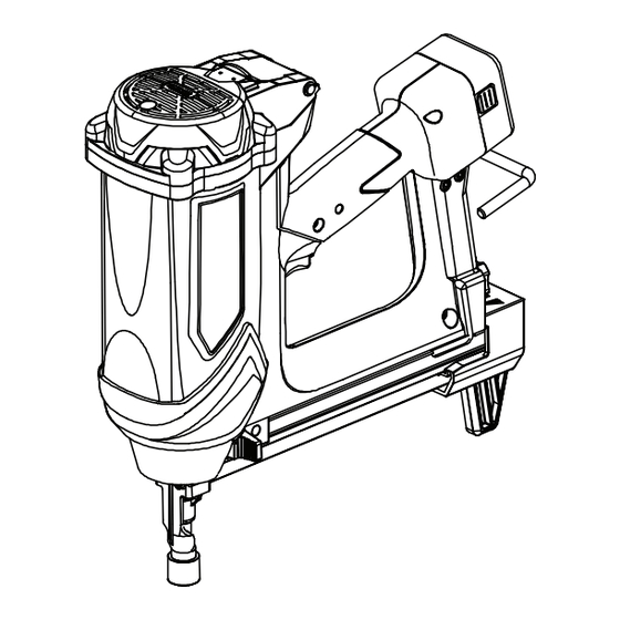
Page 9: Name Of Parts
GENERAL OPERATION MANUAL NOTE: The information contained in this Manual is designed to assist you in the safe operation of the Nailer. Some illustrations in this Manual may show details or attachments that differ from those on your own Nailer. NAME OF PARTS 1. -
Page 10: Standard Accessories
4. Accessories 1. How to install the battery Align the battery with the groove in tool handle and slip it into place. Always insert it all the way until it locks in place with a little click. If not, it may accidentally fall out of the tool, causing injury to you or someone around you. -
Page 11: Service Center
NOTE: The battery charging time becomes longer ■ If the battery charger does not work while the when a temperature is low or the voltage of battery is mounted correctly, it is probable that the power source is too low. the battery or charger is malfunctioning. -
Page 12: Testing The Nailer
■ Do not spray to a naked flame or MAGAZINE ASSEMBLY INSTALL any incandescent material. (1) REMOVE FUEL CELL AND BATTERY FROM ■ Do not smoke when handling NAILER. fuel cell. ■ Keep stem of fuel cell away from (2) Fit on the magazine assembly .Insert magazine face or skin. - Page 13 Flashing GREEN: Enough power remaining Before actually beginning the nailing work, test the (The light turns steady during operation). Nailer by using the checklist below. Conduct the Flashing RED: Insufficient power remaining tests in the following order. (The light turns steady during operation). If abnormal operation occurs, stop using Nailer and contact a authorized service center immediately.
-
Page 14: Loading Nails
Nail Feeding Step (4) Remove the finger from the trigger and press the (1) Insert nails into the back of the magazine push lever against the workpiece with pulling (see chart a) backward the feeder knob, motor fan start. Plastic strip nails Depress push lever against the Do not pull... -
Page 15: Nailer Operation
■ Do not touch around the exhaust Removing the nails: outlet with bare hands. (1) Pull the feeder knob backward to leave the The push lever and nose will nails a little distance, press the knob of the nail become hot and get heated up feeder (see chart e) . -
Page 16: Methods Of Operation
Nail Jam Remove downward nailer 2~3 times, pulling the trigger , In fire process meet the nail jam malfuction,remove the nails will be driven. Or use after put the it according the following steps: nailer and fuel cell indoor 30 minutes. (1) Remove the fuel cell and the battery;... -
Page 17: Maintenance And Inspection
MAINTENANCE Note When the pins are fire into smooth surface, suggest use the pushing arm jacket, such as NOTE: the sheet steel; ■ The information contained in this Manual is designed When nails are fire into the wood, suggest to assist you in the safe maintenance of the Nailer. do not use the pushing arm jacket. -
Page 18: Warning Label
Remove paper chips or wooden chips which 6. Operator troubleshooting may have accumulated in the magazine. See page 18. Lubricate it with GFS designated lubricant oil. ③ CAUTION Repair, modification and inspection of Power Tools must be carried out together with the... -
Page 19: Check Method
Note the color of the light indicator. If red: charge the battery. If green: Contact GFS for replacement. Inspect if the battery temperature within Wait the battery temperature as Unable to charge battery require range 50°F( 10°C) ~ 104°F (40°C). -
Page 20: Exploded Drawing And Parts List
EXPLODED DRAWING AND PARTS LIST GAS CONCRETE NAILER MODEL: GSN40-30 72-2 72-1 81-1 25 26 46 47 44 45 93 92 91 90 89 101 100 99 98 501-1 501-2... - Page 21 PART LIST GSN40-30 Drawings No. Parts Name Drawings No. Parts Name 504.3.01.01.0510.01 61 504.1.03.0001.02.02 Hex Bolt M5×10 Pushing arm 504.1.04.0011.01.02 Hex Bolt 504.2.01.0001.01.01 Top Cover 504.2.04.0001.01.01 Filter 504.2.01.0026.01.00 Pushing arm jacket Filter Cover 504.2.01.0002.01.01 504.3.03.02.0500.01 Locknut Retaining Ring d0=24 504.3.05.01.2400.01 Right Handle 504.2.01.0009.02.0 Gasket...
- Page 22 EXPLODED DRAWING AND PARTS LIST GAS CONCRETE NAILER MODEL: GSN40- 40 72-2 72-1 81-1 25 26 46 47 44 45 93 92 91 90 89 101 100 99 98 501-1 501-2...
- Page 23 PART LIST GSN40- 40 Drawings No. Parts Name Drawings No. Parts Name 504.3.01.01.0510.01 61 504.1.03.0001.02.02 Hex Bolt M5×10 Pushing arm 504.1.04.0011.01.02 Hex Bolt 504.2.01.0001.01.01 Top Cover 504.2.04.0001.01.01 Filter 504.2.01.0026.01.00 Pushing arm jacket Filter Cover 504.2.01.0002.01.01 504.3.03.02.0500.01 Locknut Retaining Ring d0=24 504.3.05.01.2400.01 Right Handle 504.2.01.0009.02.0...
- Page 24 Tengya (Nanjing) Plastic Metal Co.,Ltd; Yitian (Nanjing) hardware Co.,Ltd. Shangfang science technology zone jiangning Nanjing Jiangsu China P.R.211103 Tel:0086-25-52174012,52174008,52174016,52174019 Email:nails@tengya-nj.com;nails@jsmail.com.cn Website:www.tengya.com...
Need help?
Do you have a question about the 1000 and is the answer not in the manual?
Questions and answers