Table of Contents
Advertisement
Quick Links
Advertisement
Table of Contents

Related Manuals for KTI KGS-3120


Summary of Contents for KTI KGS-3120
- Page 1 KGS-3120 Operation Manual DOC.041230 - 1 -...
- Page 2 KTI Networks Inc. KTI Networks Inc. reserves the right to revise this documentation and to make changes in content from time to time without obligation on the part of KTI Networks Inc. to provide notification of such revision or change.
- Page 3 The information contained in this document is subject to change without prior notice. Copyright (C). All Rights Reserved. TRADEMARKS Ethernet is a registered trademark of Xerox Corp. WARNING: This equipment has been tested and found to comply with the limits for a Class A digital device, pursuant to Part 15 of the FCC Rules.
-
Page 4: Table Of Contents
Table of Contents About This Manual ......................8 Intended Readers ............................8 Typographical Conventions .......................... 8 Notes, Notices, and Cautions ........................9 Safety Instructions ............................9 Protecting Against Electrostatic Discharge ....................11 Section 1 Introduction ....................12 Switch Description ............................. 12 Features .............................. - Page 5 STP Switch Settings ........................... 64 STP Port Settings ............................66 Forwarding & Filtering ..........................68 Unicast Forwarding ............................ 68 Multicast Forwarding ..........................69 VLANs ................................. 70 802.1Q Static VLANs ..........................75 802.1Q Port Settings ..........................78 QoS ................................79 802.1p Default Priority ..........................80 802.1p User Priority ............................
- Page 6 SSH Algorithm ............................160 SSH User Authentication .......................... 162 Access Authentication Control ......................... 163 Policy & Parameters ..........................164 Application Authentication Settings ......................165 Authentication Server Group ........................166 Authentication Server Host ........................167 Login Method Lists ........................... 168 Enable Method Lists ..........................170 Local Enable Password ...........................
- Page 7 Save Changes ............................212 Factory Reset ............................213 Restart System ............................214 Logout ............................... 214 Appendix A Technical Specifications ..............215 Appendix B Cables and Connectors ..............216 Appendix C Cable Lengths ..................217 Glossary ........................218 - 7 -...
-
Page 8: About This Manual
Configuration is divided into two chapters, Basic Configura- tion and Advanced Configuration. Intended Readers This Manual contains information useful for setup and management and of the KGS-3120 Switch. This manual is intended for network managers familiar with network management concepts and terminol- ogy. -
Page 9: Notes, Notices, And Cautions
Notes, Notices, and Cautions A NOTE indicates important information that helps you make better use of your device. A NOTICE indicates either potential damage to hardware or loss of data and tells you how to avoid the problem. A CAUTION indicates a potential for property damage, personal injury, or death. Safety Instructions Use the following safety guidelines to ensure your own personal safety and to help protect your system from potential damage. - Page 10 • To help avoid damaging your system, be sure the voltage selection switch (if provided) on the power supply is set to match the power available at your location: * 115 volts (V)/60 hertz (Hz) in most of North and South America and some Far Eastern countries such as South Korea and Taiwan * 100 V/50 Hz in eastern Japan and 100 V/60 Hz in western Japan * 230 V/50 Hz in most of Europe, the Middle East, and the Far East...
-
Page 11: Protecting Against Electrostatic Discharge
rack on its slide assemblies at one time. The weight of more than one extended compo- nent could cause the rack to tip over and may result in serious injury. • Before working on the rack, make sure that the stabilizers are secured to the rack, extended to the floor, and that the full weight of the rack rests on the floor. -
Page 12: Section 1 Introduction
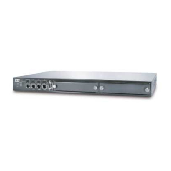
Management Options Switch Description The KGS-3120 is a modular Gigabit Ethernet backbone Switch designed for adaptability and scalability. The Switch can utilize up to twelve Gigabit Ethernet ports to function as a central distribution hub for other Switches or Switch groups, or routers. The four built-in combination Gigabit ports have the option of being used as either 1000BASE-T or SFP Gigabit connections. -
Page 13: Front-Panel Components
• Supports TFTP upgrade • Supports System Log • Fully configurable either in-band or out-of-band control via RS-232 console serial connection. • Telnet remote control console • Traffic Segmentation • Simple Network Time Protocol • MAC address update notification • Web GUI Traffic Monitoring •... -
Page 14: Led Indicators
LED Indicators The LED indicators of the Switch include Power, Console, and Link/Act. The following shows the LED indicators for the Switch along with an explanation of each indicator. LED Indicators Power This indicator on the front panel should be lit during the Power-On Self Test (POST). It will light green approximately two seconds after the Switch is powered on to indicate the ready state of the device. -
Page 15: Plug-In Modules
Plug-in Modules The KGS-3120 Switch is able to accommodate optional plug-in modules in order to increase function- ality and performance. Two modules may be installed and used in combination with any of the three available modules. Plug-in modules must be purchased separately. - Page 16 Web-based Management Interface After you have successfully installed the Switch, you can configure the Switch, monitor the LED panel, and display statistics graphically using a web browser, such as Opera, Netscape Navigator (version 6.2 and higher) or Microsoft Internet Explorer (version 5.0). To access the Switch through a web browser, the computer running the web browser must have IP-based network access to the Switch.
-
Page 17: Section 2 Installation
Connecting Devices to the Switch Package Contents Before you begin installing the Switch, confirm that your package contains the following items: • One KGS-3120 Switch unit • Mounting kit: 2 mounting brackets and screws • Four rubber feet with adhesive backing •... - Page 18 Install rubber feet for installations with or without a rack Installing the Switch in a Rack You can install the Switch in most standard 19-inch (48.3-cm) racks. Refer to the illustrations below. 1. Use the supplied screws to attach a mounting bracket to each side of the Switch. 2.
- Page 19 Mounting the Switch in a Standard 19" Rack Install Switch in equipment rack Unit ID Display The 7-segment LED (as shown below) on the front panel will always display F (15 in hex). KGS-3120 Front Panel -19-...
- Page 20 External Redundant Power System The Switch supports an external redundant power system RSPS-A60W. See the RSPS-A60W documentation for more information. Do not use the Switch with any redundant power system other than the RSPS-A60W. Connecting the Console Port The Switch provides an RS-232 serial port that enables a connection to a computer or terminal for monitoring and configuring the Switch.
- Page 21 Password Protection The KGS-3120 does not have a default user name and password. One of the first tasks when settings up the Switch is to create user accounts. If you log in using a predefined administrator-level user name you have privileged access to the Switch’s management software.
- Page 22 The sample below illustrates a successful creation of a new administrator-level account with the user name [newmanager]: KGS-3120:4#create account admin newmanager Command: create account admin newmanager Enter a case-sensitive new password:******** Enter the new password again for confirmation:******** Success. KGS-3120:4# CLI configuration commands only modify the running configuration file and are not saved when the Switch is rebooted.
-
Page 23: Power On Self Test
SNMP version may also be set for a listed group of SNMP managers. Thus, you may create a group of SNMP managers that are allowed to view read-only information or receive traps using SNMP v.1 while assigning a higher level of security to another group, granting read/write privileges using SNMP v.3. - Page 24 The IP interface named System on the Switch can be assigned an IP address and subnet mask that can then be used to connect a management station to the Switch’s Telnet or Web-based management agent. KGS-3120 Gigabit Ethernet Switch Command Line Interface Firmware Build 2.00-B17 Copyright (C) 2000-2003 All right reserved.
-
Page 25: Section 3 Basic Switch Management
Section 3 Basic Switch Management • Before You Start • General Deployment Strategy • Web-based User Interface • Basic Setup • Switch Information • Switch IP Settings • Security IP Management Stations • User Accounts Management • Saving Changes • Factory Reset •... -
Page 26: Vlan Setup
4. Determine how each subnet will communicate with the WAN or Internet. Again, static routes should be determined and default gateways identified. 5. Develop a security scheme. Some subnets on the network need more security or should be isolated from the other subnets. IP or MAC filtering can be used. Also, one or more VLANs on the Layer 3 Switch can be configured without an IP subnet, in which case, these VLANs will function as a layer 2 VLAN and would require an external router to connect to the rest of the network. - Page 27 Main Web-Manager window Area Function Right top Presents a graphical near real-time image of the front panel of the Switch. This area displays the Switch’s ports and expansion modules. Click on the ports in the front panel to manage the port’s configuration or view data for the port.
-
Page 28: Login To Web Manager
Login to Web Manager To begin managing the Switch simply run the browser you have installed on your computer and point it to the IP address you have defined for the device. The URL in the address bar should read something like: http://123.123.123.123, where the numbers 123 represent the IP address of the Switch. -
Page 29: Basic Setup
Basic Setup The subsections below describe how to change some of the basic settings for the Switch such as changing IP settings and assigning user names and passwords for management access privileges, as well as how to save the changes and restart the Switch. Switch Information The first page displayed upon logging in is the System Information (Basic Settings) window. -
Page 30: Switch Ip Settings
Switch IP Settings Switch IP settings may initially be set using the console interface prior to connecting to it through the Ethernet. If the Switch IP address has not yet been changed, read the Introduction of the CLI Refer- ence or skip ahead to the end of this section for a quick description of how to use the console port and CLI IP settings commands to establish IP settings for the Switch. - Page 31 To use the BOOTP or DHCP protocols to assign the Switch an IP address, subnet mask, and default gateway address: Use the Get IP From pull-down menu to choose from BOOTP or DHCP. This selects how the Switch will be assigned an IP address on the next reboot. The Switch IP Settings options are: BOOTP The Switch will send out a BOOTP broadcast request when it is powered up.
-
Page 32: Security Ip Management Stations Configuration
Setting the Switch’ ’ ’ ’ ’ s IP Address using the Console Interface Each Switch must be assigned its own IP Address, which is used for communication with an SNMP network manager or other TCP/IP application (for example BOOTP, TFTP). The Switch’s default IP address is 10.90.90.90. -
Page 33: User Account Management
User Account Management Use the User Account Management to control user privileges. To view existing User Accounts, open the Management folder and click on the User Accounts link. This will open the User Account Manage- ment window, as shown below. User Account Management window To add a new user, click on the [Add] button. -
Page 34: Save Changes
Admin privileges may not be available to those with User privileges. The following table summarizes the Admin and User privileges: Management Admin User Configuration Read Only Network Monitoring Read Only Community Strings and Trap Stations Read Only Update Firmware and Configuration Files Yes System Utilities PING Only Factory Reset... -
Page 35: Factory Reset
Factory Reset Click the Factory Reset link in the Maintenance folder to bring up the following window. Factory Reset to Default Value window The following options are available to perform a factory reset: Reset Returns all configuration settings to the factory default settings except the Switch’s IP address, subnet mask, and default gateway settings. -
Page 36: Restart System
Restart System The following window is used to restart the Switch. Access this window by clicking on the Restart System link in the Maintenance folder. Click the [Yes] after [Do you want to save the settings?] to instruct the Switch to save the current configuration to non-volatile RAM before restarting the Switch. -
Page 37: Advanced Settings
Advanced Settings Switch Information (Advanced Settings) window The Advanced Settings options are summarized in the table below: Serial Port Auto Logout Select the logout time used for the console interface. This automatically logs the user out after an idle period of time as defined. Choose from the following options: 2 Minutes, 5 Minutes, 10 Minutes, 15 Minutes or Never. - Page 38 configure IGMP Snooping for individual VLANs, use the IGMP Snooping window in the IGMP folder. Multicast router Only If this option is enabled and IGMP Snooping is also enabled, the Switch forwards all multicast traffic to a multicast-enabled router only. Otherwise, the Switch will forward all multicast traffic to any IP router.
-
Page 39: Section 4 Basic Configuration
Section 4 Basic Configuration • Switch Information • IP Address • Advanced Settings • Port Configuration • Port Description • Port Mirroring • Traffic Control • Link Aggregation • LACP Port Settings • Port Access Entity • 802.1X Authenticator Settings •... -
Page 40: Switch Information
The Web interface is divided into six main folders: Configuration, Security, Management, Moni- toring, Maintenance, and Single IP Management. This chapter describes all of the Configuration sub-folders and windows except those found in the Layer 3 IP Networking sub-folder, which are explained in the next chapter, Advanced Configuration. - Page 41 Switch IP Settings window below. Switch IP Settings window The Switch’s factory default IP address is 10.90.90.90 with a subnet mask of 255.0.0.0 and a default gateway of 0.0.0.0. To manually assign the Switch’ s IP address, subnet mask, and default gateway address: 1.
- Page 42 Manual Allows the entry of an IP address, Subnet Mask, and a Default Gateway for the Switch. These fields should be of the form xxx.xxx.xxx.xxx, where each xxx is a number (represented in decimal form) between 0 and 255. This address should be a unique address on the network assigned for use by the network administra- tor.
-
Page 43: Advanced Settings
Advanced Settings Switch Information (Advanced Settings) window The Advanced Settings options are summarized in the table below: Serial Port Auto Logout Select the logout time used for the console interface. This automatically logs the user out after an idle period of time as defined. Choose from the following options: 2 Minutes, 5 Minutes, 10 Minutes, 15 Minutes or Never. - Page 44 configure IGMP Snooping for individual VLANs, use the IGMP Snooping window in the IGMP folder. Multicast router Only If this option is enabled and IGMP Snooping is also enabled, the Switch forwards all multicast traffic to a multicast-enabled router only. Otherwise, the Switch will forward all multicast traffic to any IP router.
-
Page 45: Port Configuration
Port Configuration To configure basic port settings such as port speed, duplex, and learning state, use the Port Configura- tion window. Click the Port Configuration link in the Configuration folder: Port Configuration window To configure Switch ports: Choose the Unit from the pull-down menu. Choose the port or sequential range of ports using the [From... -
Page 46: Port Description
Port Description Setting window The user may set the following parameters: Unit This is the Unit ID of a Switch. The number 15 indicates a KGS-3120 Switch. From/To A consecutive group of ports may be configured starting with the selected port. -
Page 47: Port Mirroring
Port Mirroring The Switch allows you to copy frames transmitted and received on a port and redirect the copies to another port. You can attach a monitoring device to the mirrored port, such as a sniffer or an RMON probe, to view details about the packets passing through the first port. Follow the steps below to set up port mirroring. -
Page 48: Traffic Control
Traffic Control Use the Traffic Control Setting window to enable or disable storm control and adjust the threshold for multicast and broadcast storms, as well as DLF (Destination Look Up Failure). Traffic control settings are applied to individual Switch modules. Traffic Control Setting window Traffic or storm control is used to stop broadcast, multicast or ARP request storms that may result when a loop is created. -
Page 49: Link Aggregation
Link Aggregation The Switch allows the creation of up to six link aggregation groups, each group consisting of up of up to eight links (ports). The aggregated links must be contiguous (they must have sequential port num- bers) except the two (optional) Gigabit ports – which can only belong to a single link aggregation group. A link aggregation group may not cross an 8-port boundary, starting with port 1 (a group may not contain ports 8 and 9, for example) and all of the ports in the group must be members of the same VLAN. - Page 50 To configure port trunk groups, click the [Add] button to add a new trunk group and then use the Port Trunking Configuration window below to set up trunk groups. To change or delete a port trunk group, click the [Modify] or [Delete] option in the Current Trunking Group Entries table pictured above. Port Trunking Configuration window The user-changeable parameters are as follows: Group ID...
-
Page 51: Lacp Port Settings
LACP Port Mode Table window The user may set the following parameters: Unit This is the Unit ID of a Switch. The number 15 indicates a KGS-3120 Switch. From/To A consecutive group of ports may be configured starting with the selected port. -
Page 52: Port Access Entity
Port Access Entity The Switch is an implementation of the server side of IEEE 802.1X-Port Based Network Access Control. Through this mechanism, users have to be authorized before being able to access the network. See the following figure: Typical 802.1X Configuration Prior to User Authentication -52-... - Page 53 Once the user is authenticated, the Switch unblocks the port that is connected to the user as shown in the next figure. Typical 802.1X Configuration with User Authentication -53-...
- Page 54 The user’s information, including account number, password, and configuration details such as IP address and billing information, is stored in a centralized RADIUS server. Typical Configuration with 802.1X Fully Implemented State Machine Name Port Timers state machine Authenticator PAE state machine The Authenticator Key Transmit state machine Reauthentication Timer state machine Backend Authentication state machine...
-
Page 55: 802.1X Authenticator Settings
802.1X Authenticator Settings To display the current 802.1X Authenticator Settings on the Switch, open the Port Access Entity folder and click on the 802.1X Authenticator Settings link: 802.1X Authenticator Settings window To configure the 802.1X Authenticator settings for a given port, click on the blue port number under the Port heading. - Page 56 The following Authenticator Settings parameters can be set: Unit Allows you to specify a Switch . The number 15 indicates a Switch. From/To A consecutive group of ports may be configured starting with the selected port. AdmDir From the pull-down menu, select whether a controlled Port that is unauthorized will exert control over communication in both receiving and transmitting direc- tions, or just the receiving direction.
-
Page 57: Pae System Control
PAE System Control To set the port authenticating settings, open the Port Access Entity folder, and then the PAE System Control folder. Finally click on the 802.1X Capability Settings link. 802.1X Capability Settings 802.1X Capability Settings window To set up the Switch’s 802.1X port-based authentication, select which ports are to be configured in the From and To fields. -
Page 58: Radius Server
RADIUS Server The RADIUS feature of the Switch allows you to facilitate centralized user administration as well as providing protection against a sniffing, active hacker. RADIUS Server Click the Radius Server link in the Radius Server folder under Port Access Entity. Authentic Radius Server Setting window The following parameters can be set: Succession... -
Page 59: Igmp
IGMP In order to use IGMP Snooping it must first be enabled for the entire Switch (see Advanced Settings). You may then fine-tune the settings for each VLAN using the IGMP Snooping Settings window. When enabled for IGMP snooping, the Switch can open or close a port to a specific Multicast group member based on IGMP messages sent from the device to the IGMP host or vice versa. - Page 60 The IGMP Snooping Settings are described below: VLAN ID The VLAN ID number. VLAN Name The VLAN name. Query Interval The Query Interval field is used to set the time (in seconds) between transmitting IGMP queries. Entries between 1 and 9,999 seconds are allowed. The default value is 125. Max Response Time This determines the maximum amount of time in seconds allowed before sending an IGMP response report.
-
Page 61: Static Router Ports
Static Router Ports A static router port is a port that has a multicast router attached to it. Generally, this router would have a connection to a WAN or to the Internet. Establishing a router port will allow multicast packets coming from the router to be propagated through the network, as well as allowing multicast messages (IGMP) coming from the network to be propagated to the router. -
Page 62: Spanning Tree
To configure a static router port(s): 1. Select the Unit containing the static router port. 2. Select the Port or Ports that will become static router ports. 3. Click [Apply] to let the changes take effect. The following parameters are listed in the Static Router Port windows. VLAN ID (VID) This is the VLAN ID that, along with the VLAN name, identifies the VLAN where the multicast router is attached. - Page 63 802.1d STP 802.1w RSTP Forwarding? Learning? Disabled Discarding Blocking Discarding Listening Discarding Learning Learning Forwarding Forwarding Comparing Port States RSTP is capable of more rapid transition to a forwarding state – it no longer relies on timer configura- tions RSTP compliant bridges are sensitive to feedback from other RSTP compliant bridge links. Ports do not need to wait for the topology to stabilize before transitioning to a forwarding state.
-
Page 64: Stp Switch Settings
STP Switch Settings The Spanning Tree Protocol (STP) operates on two levels: on the Switch level, the settings are globally implemented. On the port level, the settings are implemented on a per user-defined group of ports basis. Switch Spanning Tree Settings window -64-... - Page 65 Configure the following system-wide STP parameters and click the [Apply] button to implement them: Spanning Tree Status <Disabled> This field can be toggled between Enabled and Disabled using the pull-down menu. This will enable or disable the Spanning Tree Protocol (STP), globally, for the Switch. Bridge Max Age (6 - 40 sec) <20 >...
-
Page 66: Stp Port Settings
STP Port Settings STP Port Settings window In addition to setting Spanning Tree parameters for use on the Switch level, the Switch allows for the configuration of groups of ports, each port-group of which will have its own spanning tree, and will require some of its own configuration settings. - Page 67 The following fields can be set for STP port configuration: Unit This is the Unit ID of a Switch. Specify the number 15. From/To A consecutive group of ports may be configured starting with the selected port. State This drop-down menu allows you to enable or disable STP for the selected group of ports.
-
Page 68: Forwarding & Filtering
Forwarding & Filtering The Switch allows permanent or static entries into the forwarding database (FDB). These FDB entries are MAC addresses that will not age out. In addition, multicast forwarding may be customized to conform to rules for the different ports by setting up multicast filter modes for each port. Unicast Forwarding Open the Forwarding &... -
Page 69: Multicast Forwarding
Multicast Forwarding The following figure and table describe how to set up Multicast forwarding on the Switch. Open the Forwarding & Filtering folder and click on the Multicast Forwarding link to see the entry window below: Static Multicast Forwarding Settings window The Static Multicast Forwarding Settings window displays all of the entries made into the Switch’s ’s static multicast forwarding table. -
Page 70: Vlans
These VLANs are based on layer 3 information, however this does not constitute a ’routing’ function. The KGS-3120 allows an IP subnet to be configured for each 802.1Q VLAN that exists on the Switch. That is, a VLAN can be associated or attached to an IP subnet. This represents an improvement in performance since it bypasses any routing functions, packets transferred between subnets are reduced to a hardware decision. - Page 71 Assigning IP Network Addresses and Subnet Masks to VLANs The KGS-3120 allows the assignment of IP subnets to individual VLANs. This is the fundamental advantage of VLANs in IP Switching. Developing an IP addressing scheme is a complex subject, but it is sufficient here to mention that the total number of anticipated end nodes - for each IP interface - must be accommodated with a unique IP address.
- Page 72 802.1Q Packet Forwarding 802.1Q VLAN Tags The figure below shows the 802.1Q VLAN tag. There are four additional octets inserted after the source MAC address. Their presence is indicated by a value of 0x8100 in the EtherType field. When a packet’s EtherType field is equal to 0x8100, the packet carries the IEEE 802.1Q/802.1p tag. The tag is contained in the following two octets and consists of three bits or user priority, one bit of Canonical Format Identifier (CFI - used for encapsulating Token Ring packets so they can be carried across Ethernet backbones) and twelve bits of VLAN ID (VID).
- Page 73 IEEE 802.1Q Tag The EtherType and VLAN ID are inserted after the MAC source address, but before the original EtherType/Length or Logical Link Control. Because the packet is now a bit longer than it was origi- nally, the Cyclic Redundancy Check (CRC) must be recalculated. Adding an IEEE 802.1Q Tag -73-...
- Page 74 Port VLAN ID Packets that are tagged (are carrying the 802.1Q VID information) can be transmitted from one 802.1Q compliant network device to another with the VLAN information intact. This allows 802.1Q VLANs to span network devices (and indeed, the entire network if all network devices are 802.1Q compliant).
-
Page 75: 802.1Q Static Vlans
packets received by and forwarded by an untagging port will have no 802.1Q VLAN information. (Remember that the PVID is only used internally within the Switch). Untagging is used to send packets from an 802.1Q-compliant network device to a non-compliant network device. Ingress Filtering A port on a Switch where packets are flowing into the Switch and VLAN decisions must be made is referred to as an ingress port. - Page 76 802.1Q Static VLANs window To configure the newly created VLAN, select the Switch being configured from the Unit drop-down menu and provide a unique VLAN identifier and name. Configure the port settings for VLAN mem- bership by selecting the appropriate options for each port. Click the [Apply] button to configure the VLAN port membership settings.
- Page 77 The illustration below displays the port settings for a new VLAN (engineering) with a VID of 11. Add New Static VLAN Example window Click the Show All Static VLAN Entries link to return to the first 802.1Q Static VLANs window, the new VLAN entry appears listed in the current entries table.
-
Page 78: 802.1Q Port Settings
802.1Q Port Settings Open the 802.1Q Port Settings window and select the Unit and range of ports to configure. For the selected port or group of ports, choose to enable or disable Ingress checking and establish an accept- able packet rule. Ingress Checking is used to limit traffic by filtering incoming packets that have a PVID does not match the PVID of the port. -
Page 79: Qos
PVID A Port VLAN Identifier is a classification mechanism that associates a port with a specific VLAN and is used to make forwarding decisions for untagged packets received by the port. For example, if port 2 is assigned a PVID of 3, then all untagged packets received on port 2 will be assigned to VLAN 3. -
Page 80: 802.1P Default Priority
802.1p Default Priority The Switch allows the assignment of a default 802.1p priority to each port on the Switch. Click on the 802.1p Default Priority link in the QoS sub-folder: Port Default Priority assignment window This page allows you to assign a default 802.1p priority to any given port on the Switch. The priority queues are numbered from 0 - the lowest priority - to 7 - the highest priority. -
Page 81: 802.1P User Priority
802.1p User Priority The KGS-3120 allows the assignment of a User Priority to each of the 802.1p priorities. User Priority Configuration window Once you have assigned a priority to the port groups on the Switch, you can then assign this Class to each of the eight levels of 802.1p priorities. -
Page 82: Qos Output Scheduling Configuration
QoS Output Scheduling Configuration QoS can be customized by changing the output scheduling used for the hardware queues in the Switch. As with any changes to QoS implementation, careful consideration should be given to how network traffic in lower priority queues are affected. Changes in scheduling may result in unacceptable levels of packet loss or significant transmission delay. -
Page 83: Traffic Segmentation
Traffic Segmentation Traffic segmentation is used to limit traffic flow from a single port to a group of ports. This method of segmenting the flow of traffic is similar to using VLANs to limit traffic, but is more restrictive. It provides a method of directing traffic that does not increase the overhead of the Master Switch CPU. -
Page 84: Bandwidth Control
Bandwidth Control The bandwidth control settings are used to place a ceiling on the transmitting and receiving data rates for any selected port. Bandwidth Settings window The following parameters can be set or are displayed: Unit Allows you to specify a Switch. Specify the number 15. From/To A consecutive group of ports may be configured starting with the selected port. -
Page 85: Mac Notification
MAC Notification MAC address notification is used to monitor MAC addresses as they are learned and entered into the Switch’s MAC forwarding database. MAC Notification Global Settings MAC Notification Global Settings window The following parameters can be set: State This drop-down menu is used to enable or disable MAC notification on the selected Switch. -
Page 86: Mac Notification Port Settings
MAC Notification Port Settings Enable or disable MAC notification for ports with the window below. MAC Notification Port Settings window The following parameters can be set: Unit Specify number 15 indicates the Switch. From/To A consecutive group of ports may be configured starting with the selected port. State This pull-down menu allows you to enable or disable MAC notification for the specified Switch and group of ports. -
Page 87: System Log Server
System Log Server Use the System Log to keep a record of warning and other pertinent system information. The Switch can send system log (SysLog) messages to up to four designated servers. System Log Servers window Click the [Add] button to bring up the window pictured below. The parameters configured for adding System Log are described in the table below. - Page 88 Configure these parameters for the system log: Index Syslog server settings index (1-4). Server IP The IP address of the Syslog server. Severity This drop-down menu allows you to select the level of messages that will be sent. The options are Warning, Informational, and ALL. Facility Some of the operating system daemons and processes have been assigned Facility values.
-
Page 89: Port Security
Port Security A given port’s (or a range of port’s) dynamic MAC address learning can be locked such that the current source MAC addresses entered into the MAC address forwarding table can not be changed once the port lock is enabled. The port can be locked by using the Admin State pull-down menu to Enabled, and clicking [Apply]. -
Page 90: Sntp Setting
SNTP Setting The Simple Network Time Protocol (SNTP) (an adaptation of the Network Time Protocol (NPT)) is configured on the Switch using the following windows. Time Setting Current Time: Status window The following parameters can set or are displayed: Current Time Displays the current system time. -
Page 91: Time Zone And Dst Settings
Time Zone and DST Settings Time Zone and DST Settings window The following parameters can set: Daylight Saving Time State Use this pull-down menu to enable or disable the DST Settings. Daylight Saving Time Offset in Minutes Use this pull-down menu to specify the amount of time that will constitute your local DST offset - 30, 60, 90, or 120 minutes. - Page 92 Enter the week of the month that DST will start. From: Which Day of Week Enter the day of the week that DST will start on. From: Which Month Enter the month DST will start on. From: What Time HH:MM Enter the time of day that DST will start on.
-
Page 93: Access Profile Table
Access Profile Table Access profiles allow you to establish criteria to determine whether or not the Switch will forward packets based on the information contained in each packet’s header. These criteria can be specified on a basis of VLAN, MAC address or IP address. Creating an access profile is divided into two basic parts. - Page 94 The following parameters can be set: Profile ID(1-255) Type in a unique identifier number for this profile set or allow an ID to be automatically assigned by checking the Auto Assign option. This value can be set from 1 to 255. Type Select profile based on Ethernet (MAC Address), IP address or packet content mask.
- Page 95 The page shown below is the Access Profile Configuration window for IP: Access Profile Configuration (IP) window The following parameters can be set: Profile ID(1-255) Type in a unique identifier number for this profile set or allow an ID to be automatically assigned by checking the Auto Assign option.
- Page 96 Dscp Selecting this option instructs the Switch to examine the DiffServ Code part of each packet header and use this as the, or part of the criterion for forwarding. Protocol Selecting this option instructs the Switch to examine the protocol type value in each frame’...
- Page 97 The window shown below is the Access Profile Configuration window for Packet Content Mask. Access Profile Configuration (Packet Content Mask) window -97-...
- Page 98 This window will aid the user in configuring the Switch to mask packet headers beginning with the offset value specified. The following fields are used to configure the Packet Content Masks: The following parameters can be set: Profile ID(1-255) Type in a unique identifier number for this profile set or allow an ID to be automatically assigned by checking the Auto Assign option.
- Page 99 To establish the rule for a previously created Access Profile, select the Access Profile entry from the Access Profile Table window and then click the [Modify] button for that individual entry. Access Rule Table window To create a new rule set for the access profile, click the [Add] button. A new window is displayed. To remove a previously created rule, select it and click the [Delete] button.
- Page 100 Configure the Access Rule Configuration settings on the window above. The following parameters can be set: Profile ID This is the identifier number for this profile set. Mode * Select Permit to specify that the packets that match the access profile are forwarded by the Switch, according to any additional rule added (see below).
- Page 101 Access Rule Configuration (IP) window Configure the Access Rule Configuration settings on the window above. -101-...
- Page 102 The following parameters can be set: Profile ID This is the identifier number for this profile set. Mode * Select Permit to specify that the packets that match the access profile are forwarded by the Switch, according to any additional rule added (see below).
- Page 103 Access Rule Configuration (Package Content Mask) window Configure the Access Rule Configuration settings on the window above. -103-...
- Page 104 The following parameters can be set: Profile ID This is the identifier number for this profile set. Mode * Select Permit to specify that the packets that match the access profile are forwarded by the Switch, according to any additional rule added (see below).
-
Page 105: Section 5 Layer 3 Ip Networking
Section 5 Layer 3 IP Networking • L3 Global Advanced Settings • IP Interface Settings • MD5 Key Settings • Route Redistribution Settings • Static/Default Route Settings • Static ARP Settings • • RIP Global Setting • RIP Interface Settings •... -
Page 106: L3 Global Advanced Settings
L3 Global Advanced Settings In order to use DVMRP, PIM-DM, RIP, or OSPF, the Switch must first be globally enabled. To enable or disable these Layer 3 protocols as well as configure ARP Aging Time, access the L3 Global Ad- vanced Settings window. - Page 107 IP Interface Settings window Enter the desired IP interface settings and click the [Apply] button. A message should appear inform- ing you if the settings have been successfully applied. For convenience, you may want to use the same name for the IP interface and the VLAN. To return to the first IP Interface Settings window, click the Show ALL IP Interface Entries link.
- Page 108 Introduction to OSPF The Open Shortest Path First (OSPF) routing protocol that uses a link-state algorithm to determine routes to network destinations. A [link] is an interface on a router and the [state] is a description of that interface and its relationship to neighboring routers. The state contains information such as the IP address, subnet mask, type of network the interface is attached to, other routers attached to the net- work, etc.
- Page 109 Shortest Path Algorithm The Shortest Path to a destination is calculated using the Dijkstra algorithm. Each router is places at the root of a tree and then calculates the shortest path to each destination based on the cumulative cost to reach that destination over multiple possible routes.
- Page 110 Constructing a Shortest Path Tree The diagram above shows the network from the viewpoint of Router A. Router A can reach 192.213.11.0 through Router B with a cost of 10+5=15. Router A can reach 222.211.10.0 through Router C with a cost of 10+10=20.
- Page 111 Note that this shortest path tree is only from the viewpoint of Router A. The cost of the link from Router B to Router A, for instance is not important to constructing Router A’ s shortest path tree, but is very important when Router B is constructing its shortest path tree.
- Page 112 responsibility of distributing routing information from the Autonomous System Border Router in order for routers in the network to get and maintain routes to other Autonomous Systems. Network link-state updates are generated by a router elected as the Designated Router on a multi- access segment (with more than one attached router).
- Page 113 border routers that have a common area, with one border router connected to the backbone. Partitioning the Backbone OSPF also allows virtual links to be configured to connect the parts of the backbone that are discon- tinuous. This is the equivalent to linking different area 0s together using a logical path between each area 0.
- Page 114 • Attempt - On non-broadcast multi-access networks (such as Frame Relay or X.25), this state indicates that no recent information has been received from the neighbor. An effort should be made to contact the neighbor by sending Hello packets at the reduced rate set by the Poll Inter- val.
- Page 115 OSPF Packet Header Field Description Version No. The OSPF version number Type The OSPF packet type. The OSPF packet types are as follows: . Hello . Database Description . Link-State Request . Link-State Update . Link-State Acknowledgment Packet Length The length of the packet in bytes. This length includes the 24-byte header. Router ID The Router ID of the packet’...
- Page 116 The format of the Hello packet is shown below: Hello Packet Field Description Network Mask The network mask associated with this interface. Options The optional capabilities supported by the router. Hello Interval The number of seconds between this router’ s Hello packets. Router Priority This router’...
- Page 117 Database Description Packet Database Description packets are OSPF packet type 2. These packets are exchanged when an adja- cency is being initialized. They describe the contents of the topological database. Multiple packets may be used to describe the database. For this purpose a poll-response procedure is used. One of the routers is designated to be master, the other a slave.
- Page 118 Link-State Request Packet Link-State Request packets are OSPF packet type 3. After exchanging Database Description packets with a neighboring router, a router may find that parts of its topological database are out of date. The Link-State Request packet is used to request the pieces of the neighbor’ s database that are more up to date.
- Page 119 Link-State Update Packet Link-State Update packets are OSPF packet type 4. These packets implement the flooding of link- state advertisements. Each Link-State Update packet carries a collection of link-state advertisements one hop further from its origin. Several link-state advertisements may be included in a single packet. Link-State Update packets are multicast on those physical networks that support multicast/broadcast.
- Page 120 Link-State Acknowledgment Packet Link-State Acknowledgment packets are OSPF packet type 5. To make the folding of link-state adver- tisements reliable, flooded advertisements are explicitly acknowledged. This acknowledgment is ac- complished through the sending and receiving of Link-State Acknowledgment packets. Multiple link- state advertisements can be acknowledged in a single Link-State Acknowledgment packet.
- Page 121 Link-State Advertisement Formats There are five distinct types of link-state advertisements. Each link-state advertisement begins with a standard 20-byte link-state advertisement header. Succeeding sections then diagram the separate link- state advertisement types. Each link-state advertisement describes a piece of the OSPF routing domain. Every router originates a router links advertisement.
- Page 122 Field Description Link State Age The time is seconds since the link state advertisement was origi- nated. Options The optional capabilities supported by the described portion of the routing domain. Link State Type The type of the link state advertisement. Each link state type has a separate advertisement format.
- Page 123 Router Links Advertisements Router links advertisements are type 1 link state advertisements. Each router in an area originates a routers links advertisement. The advertisement describes the state and cost of the router’ s links to the area. All of the router’ s links to the area must be described in a single router links advertisement. The format of the Router Links Advertisement is shown below: Routers Links Advertisement In router links advertisements, the Link State ID field is set to the router’...
- Page 124 Field Description V - bit When set, the router is an endpoint of an active virtual link that is using the described area as a Transit area (V is for Virtual link endpoint). E - bit When set, the router is an Autonomous System (AS) boundary router (E is for External).
- Page 125 For each link, separate metrics may be specified for each Type of Service (TOS). The metric for TOS 0 must always be included, and was discussed above. Metrics for non-zero TOS are described below. Note that the cost for non-zero TOS values that are not specified defaults to the TOS 0 cost. Metrics must be listed in order of increasing TOS encoding.
- Page 126 Summary Link Advertisements Summary link advertisements are Type 3 and 4 link state advertisements. These advertisements are originated by Area Border routers. A separate summary link advertisement is made for each destina- tion known to the router, that belongs to the Autonomous System (AS), yet is outside the area. Type 3 link state advertisements are used when the destination is an IP network.
- Page 127 Autonomous Systems External Link Advertisements Autonomous Systems (AS) link advertisements are Type 5 link state advertisements. These advertise- ments are originated by AS boundary routers. A separate advertisement is made for each destination known to the router, that is external to the AS. AS external link advertisements usually describe a particular external destination.
-
Page 128: Md5 Key Settings
MD5 Key Settings MD5 authentication is used to identify trusted routers sending OSPF packets. By default no authenti- cation is used for OSPF so it is not necessary to configure any MD5 keys to use OSPF. MD5 authen- tication can be set up at any time, before or after you have configured OSPF settings. The MD5 Key Setting window allows the entry of a 16-character Message Digest - version 5 (MD5) key that can be used to authenticate every packet exchanged between OSPF routers. -
Page 129: Route Redistribution Settings
This information is then exchanged among the various routers according to the individual routers current routing protocol. The KGS-3120 can redistribute routing information between the OSPF and RIP routing protocols to all routers on the network that are running OSPF or RIP. -
Page 130: Static/Default Route Settings
Static/Default Route Settings Static routes that have been previously configured appear in the Static/Default Route Settings table. To add a new route, click on the [Add] button, a new window appears. To remove an existing route, click the [X] button in the Delete column for the route you want to eliminate. Static/Default Route Settings window Use the Static/Default Route Settings - Add window to configure IP settings and Metric cost for the new route. -
Page 131: Static Arp Settings
Static ARP Settings Use the Static ARP Settings window to create permanent entries in the ARP table for different IP interfaces. Static ARP entries that have been configured appear in the Static ARP Settings table in this window. To add a new static ARP entry, click on the [Add] button, a new window appears (see below). -
Page 132: Rip
The Switch supports the Routing Information Protocol (RIP). RIP Global Setting To setup Routing Information Protocol (RIP) for the IP interfaces configured in the Switch, open the RIP folder and click on the RIP Global Setting link. Use the RIP Global Setting window to first enable RIP and then configure RIP settings for the individual IP interfaces. - Page 133 Refer to the table below for a description of the available parameters for RIP interface settings. To return to the RIP Interface Settings table, click the Show All RIP Interface Settings link. The following RIP settings can be applied to each IP interface: Interface Name The name of the IP interface on which RIP is to be setup.
-
Page 134: Ospf
OSPF All the links for OSPF configuration windows are contained within the OSPF sub-folder of the Layer 3 IP Networking folder (located under Configuration). OSPF General Setting The OSPF General Setting window allows OSPF to be enabled or disabled on the Switch - without changing the Switch’s OSPF configuration. -
Page 135: Ospf Area Id Settings
OSPF Area ID Settings This window allows the configuration of OSPF Area IDs and to designate these areas as either Nor- mal or Stub. Normal OSPF areas allow Link-State Database (LSDB) advertisements of routes to networks that are external to the area, while stub areas do not allow the LSDB advertisement of external routes. -
Page 136: Ospf Interface Settings
OSPF Interface Settings To set up OSPF interfaces, click the OSPF Interface Settings link to view OSPF settings for existing IP interfaces. If there are no IP interfaces configured (besides the default System interface), only the System interface settings will appear listed. To change settings for in IP interface, click on the hyperlinked name of the interface to see the configuration menu for that interface. - Page 137 OSPF interface settings are described below. Some OSPF interface settings require previously configured OSPF settings. Read the descriptions below for details. Interface NameDisplays the of an IP interface previously configured on the Switch. Area ID Allows the entry of an OSPF Area ID configured above. Router Priority Allows the entry of a number between 0 and 255 representing the OSPF priority of the selected area.
-
Page 138: Ospf Virtual Interface Settings
OSPF Virtual Interface Settings Click the OSPF Virtual Interface Settings link to view the current OSPF virtual interface settings. There are not virtual interface settings configured by default, so the first time this table is viewed there will be not interfaces listed. To add a new OSPF virtual interface configuration set to the table, click the [Add] button. -
Page 139: Ospf Area Aggregation Settings
neighbor router before the selected area declares that router down. Again, all routers on the network should use the same setting. Auth Type If using authorization for OSPF routers, select the type being used. MD5 key authorization must be set up in the MD5 Key Settings window. Password/Auth. -
Page 140: Ospf Host Route Settings
Specify the OSPF Aggregation settings and click the [Apply] button to add or change the settings. The new settings will appear listed in the OSPF Area Aggregation Settings window. To view the table, click the Show All OSPF Aggregation Entries link to return to the previous window. Configure the following settings for OSPF Area Aggregation: Area ID Allows the entry the OSPF Area ID for which the routing information will be... -
Page 141: Dhcp/Bootp Relay
the Show All OSPF Host Route Entries link to return to the previous window. The following fields are configured for OSPF host route: Host Address The IP address of the OSPF host. Metric A value between 1 and 65,535 that will be advertised for the route. Area ID A 32-bit number in the form of an IP ad dress (xxx.xxx.xxx.xxx) that uniquely identifies the OSPF area in the OSPF domain. -
Page 142: Dns Relay
To create a new relay configuration, enter the IP interface name you want to configure for DHCP relay and the IP address of the server. Click on the [Add] button to enter the relay settings. Up to four servers can be entered for each IP interface. The information listed in the window is described as follows: Interface The name of the IP interface in which BOOTP relay is to be enabled. -
Page 143: Vrrp
To configure permanent entries for the DNS Relay Static Table, use the following window. DNS Relay Static Settings DNS Relay Static Settings window To create a new DNS Relay Static entry, enter the Domain Name and the associated IP address. Click on the [Add] button to enter the settings into the static table. -
Page 144: Vrrp Configuration
VRRP Configuration To enable VRRP globally on the Switch, click Configuration > Layer 3 IP Networking > VRRP > VRRP Configuration: VRRP Configuration window The following fields can be set: Global VRRP Use the pull-down menu to enable or disable VRRP globally on the Switch. -
Page 145: Vrrp Interface Settings
VRID Displays the virtual router ID set by the user. This will uniquely identify the VRRP Interface on the network. Display Click the [View] button to display the settings for this particular VRRP entry. Delete Click the [X] to delete this VRRP entry. Click the [Add] button to display the following window to configure a VRRP interface. - Page 146 router overrides a lower priority VRRP router. A higher priority will increase the probability that this router will become the Master router of the group. A lower priority will increase the probability that this router will become the backup router. VRRP routers that are assigned the same priority value will elect the highest physical IP address as the Master router.
-
Page 147: Vrrp Interface Entry Display
VRRP Interface Entry Display To view the settings for a particular VRRP setting, click the corresponding in the VRRP Interface Table window of the entry, which will display the following: VRRP Interface Entry Display window This window displays the following information: Interface Name An IP interface name that has been enabled for VRRP. -
Page 148: Ip Multicast
Priority Displays the priority of the virtual router. A higher priority will increase the probability that this router will become the Master router of the group. A lower priority will increase the probability that this router will become the backup router. The lower the number, the higher the priority. Master IP Address Displays the IP address of the Master router for the VRRP function. -
Page 149: Igmp Interface Configuration
IGMP Interface Configuration IGMP Interface Configuration window Configure IGMP settings for each IP interface and click on the [Apply] button to apply the new or changed settings. The new values will appear in the IGMP Interface Table. To view the table click Show All IGMP Interface Entries. -
Page 150: Dvmrp
DVMRP For a description of how Distance Vector Multicast Routing Protocol (DVMRP) works, please read Appendix C. The DVMRP settings links are located in the DVMRP subfolder located in the Layer 3 IP Networking configuration folder. DVMRP Global Setting To use DVMRP on the Switch it must be enabled globally. Use the DVMRP Global Setting window to enable or disable DVMRP globally. - Page 151 Configure DVMRP settings for each IP interface and click on the [Apply] button to apply the new or changed settings. The new values will appear in the DVMRP Interface Settings table in the previous window. To view the table click Show All DVMRP Interface Entries. The table below describes the parameters necessary for DVMRP configuration.
-
Page 152: Pim
For a description of how Protocol Independent Multicast-Dense Mode (PIM-DM) functions, please read Appendix C. The PIM-DM settings links are located in the PIM subfolder located in the Layer 3 IP Networking folder. PIM-DM Global Setting To use PIM-DM on the Switch it must be enabled globally. Use the PIM-DM Global Setting window to enable or disable PIM-DM globally. - Page 153 Configure PIM-DM settings for each IP interface and click on the [Apply] button to apply the new or changed settings. The new values will appear in the 1 PIM-DM Interface Settings window. To view the table click Show All PIM-DM Interface Entries. The table below describes the parameters necessary for PIM-DM configuration.
-
Page 154: Section 6 Security
Section 6 Security • Trusted Host • Secure Socket Layer (SSL) • Download Certificate • Configuration • Secure Shell (SSH) • SSH Configuration • SSH Algorithm • SSH User Authentication • Access Authentication Control • Policy and Parameters • Application Authentication Settings •... -
Page 155: Secure Socket Layer (Ssl)
Secure Socket Layer (SSL) Secure Sockets Layer or SSL is a security feature that will provide a secure communication path between a host and client through the use of authentication, digital signatures and encryption. These security functions are implemented through the use of a ciphersuite, which is a security string that determines the exact cryptographic parameters, specific encryption algorithms and key sizes to be used for an authentication session and consists of three levels: Key Exchange: The first part of the cyphersuite string specifies the public key algorithm to be... -
Page 156: Download Certificate
Download Certificate This window is used to download a certificate file for the SSL function on the switch from a TFTP server. The certificate file is a data record used for authenticating devices on the network. It contains information on the owner, keys for authentication and digital signatures. Both the server and the client must have consistent certificate files for optimal use of the SSL function. - Page 157 Switch and need to be configured using the command line interface. For more information on SSL and its functions, see the KGS-3120 Command Line Reference Manual, located on the documentation CD of this product.
-
Page 158: Secure Shell (Ssh)
Secure Shell (SSH) SSH is the abbreviation of Secure Shell, which is a program allowing secure remote login and secure network services over an insecure network. It allows you to securely login to remote host computers, to execute commands safely in a remote computer and so forth, and to provide secure encrypted and authenticated communications between two non-trusted hosts. -
Page 159: Ssh Configuration
SSH Configuration The following window is used to configure and view settings on the SSH server and can be opened by clicking Security > Secure Shell (SSH) > SSH Configuration: Current SSH Configuration Settings window To set up the SSH server on the switch, configure the following parameters and click [Apply]. SSH Server Status Use the pull-down menu to enable or disable SSH on the switch. -
Page 160: Ssh Algorithm
SSH Algorithm The Encryption Algorithm window allows the configuration of the desired types of SSH algorithm used for authentication encryption. There are four categories of algorithms listed and specific algorithms in each may be enabled or disabled by using their corresponding pull-own menu. All algorithms are en- abled by default. - Page 161 AES192-CBC Use the pull-down menu to enable or disable the Advanced Encryption Standard AES192 encryption algorithm with Cipher Block Chaining. The default is En- abled. AES256-CBC Use the pull-down menu to enable or disable the Advanced Encryption Standard AES256 encryption algorithm with Cipher Block Chaining. The default is En- abled.
-
Page 162: Ssh User Authentication
SSH User Authentication The following windows are user to configure parameters for users attempting to access the Switch through SSH. To access the following window, click Security > Secure Shell (SSH) > SSH User Authentication. Current Accounts window In the example window above, no user account has been previously set using the User Accounts window in the Management folder. -
Page 163: Access Authentication Control
To set the SSH User Authentication parameters on the Switch, a user account must be previously configured. For more information on configuring local user accounts on the Switch, see the Security IP section of this document. Access Authentication Control The TACACS/XTACACS/TACACS+/RADIUS commands let you secure access to the switch using the TACACS/XTACACS/TACACS+/RADIUS protocols. -
Page 164: Policy & Parameters
thentication Server Groups can only have TACACS Authentication Server Hosts. The administrator for the switch may set up six different authentication techniques per user-defined method list (TACACS/XTACACS/TACACS+/RADIUS/local/none) for authentication. These tech- niques will be listed in an order preferable, and defined by the user for normal user authentication on the switch, and may contain up to eight authentication techniques. -
Page 165: Application Authentication Settings
Click [Apply] to implement changes made. Application Authentication Settings This window is used to configure switch configuration applications (console, Telnet, SSH, and web) for login at the user level and at the administration level (Enable Admin) utilizing a previously configured method list. -
Page 166: Authentication Server Group
Authentication Server Group This window will allow users to set up Authentication Server Groups on the Switch. A server group is a technique used to group RADIUS, TACACS, TACACS+, and XTACACS server hosts into user- defined categories for authentication using method lists. The user may define the type of server group by protocol or by previously defined server group. -
Page 167: Authentication Server Host
The four built in server groups can only have server hosts running the same TACACS/ RADIUS daemon. RADIUS, TACACS, TACACS+, and XTACACS protocols are separate entities and are not compatible with each other. Authentication Server Host This window will set user-defined Authentication Server Hosts for the RADIUS, TACACS, TACACS+, and XTACACS security protocols on the switch. -
Page 168: Login Method Lists
protocol. TACACS+ - Enter this parameter if the server host utilizes the TACACS+ protocol. RADIUS - Enter this parameter if the server host utilizes the RADIUS protocol. Port(1-65535) Enter a number between 1 and 65535 to define the virtual port number of the authentication protocol on a server host. - Page 169 To view the following window, click Security > Access Authentication Control > Login Method Lists: Login Method Lists Settings window The Switch contains one Method List that is set and cannot be removed, yet can be modified. To delete a Login Method List defined by the user, click the under the Delete heading corresponding to the entry desired to be deleted.
-
Page 170: Enable Method Lists
Enable Method Lists This window is used to set up Method Lists to promote users with normal level privileges to Adminis- trator level privileges using authentication methods on the Switch. Once a user acquires normal user level privileges on the Switch, he or she must be authenticated by a method on the Switch to gain administrator privileges on the Switch, which is defined by the Administrator. - Page 171 Enable Method List - Edit window To define an Enable Login Method List, set the following parameters and click [Apply]: Method List Name Enter a method list name defined by the user of up to 15 characters. Method 1, 2, 3, 4 The user may add one, or a combination of up to four of the following authentication methods to this method list: local_enable - Adding this parameter will require the user to be authenti-...
-
Page 172: Local Enable Password
Local Enable Password This window will configure the locally enabled password for Enable Admin. When a user chooses the Local_Enable method to promote user level privileges to administrator privileges, he or she will be prompted to enter the password configured here that is locally set on the Switch. To view the following window, click Security >... - Page 173 To view the following window, click Security > Access Authentication Control > Enable Admin: Enable Admin window When this window appears, click the [Enable Admin] button revealing a dialog box for the user to enter authentication (password, username), as seen below. A successful entry will promote the user to Administrator level privileges on the switch.
-
Page 174: Section 7 Management
Section 7 Management • User Accounts • SNMPV3 • SNMP User Table • SNMP View Table • SNMP Group Table • SNMP Community Table • SNMP Host Table • SNMP Engine ID • User Accounts Use the User Account Management to control user privileges. To view existing User Accounts, open the Management folder and click on the User Accounts link. - Page 175 Add a new user by typing in a User Name, and New Password and retype the same password in the Confirm New Password. Choose the level of privilege (Admin or User) from the Access Right drop- down menu. Modify or delete an existing user account in the User Account Modify Table window. To delete the user account, click on the [Delete] button.
-
Page 176: Snmpv3
Use the SNMP V3 windows to select the SNMP version used for specific tasks. The KGS-3120 supports the Simple Network Management Protocol (SNMP) versions 1, 2c, and 3. The SNMP version used to monitor and control the Switch can be specified by the administrator. The three versions of SNMP vary in the level of security provided between the management station and the network device. - Page 177 User Name An alphanumeric string of up to 32 characters. This is used to identify the SNMP users. Group Name This name is used to specify the SNMP group created can request SNMP messages. SNMP Version V1 - Indicates that SNMP version 1 will be used. V2 - Indicates that SNMP version 2 will be used.
-
Page 178: Snmp View Table
used. Priv-Protocol None - Specifies that no authorization protocol is in use. DES - Specifies that DES 56-bit encryption is in use based on the CBC- DES (DES-56) standard. SNMP View Table The SNMP View Table is used to assign views to community strings that define which MIB objects can be accessed by a remote SNMP manager. -
Page 179: Snmp Group Table
The following parameters can set: View Name Type an alphanumeric string of up to 32 characters. This is used to identify the new SNMP view being created. Subtree OID Type the Object Identifier (OID) Subtree for the view. The OID identifies an object tree (MIB tree) that will be included or excluded from access by an SNMP manager. - Page 180 SNMP Group Table Display To display the current settings for an existing SNMP Group Table entry, click the blue hyperlink for the entry under the Group Name heading. SNMP Group Table Display window To add a new entry to the Switch’s SNMP Group Table, click the [Add] button in the upper left-hand corner of the SNMP Group Table window.
- Page 181 The following parameters can be set: Group Name Type an alphanumeric string of up to 32 characters. This is used to identify the new SNMP group of SNMP users. Read View Name This name is used to specify the SNMP group created can request SNMP messages.
-
Page 182: Snmp Community Table
SNMP Community Table Use this table to create an SNMP community string to define the relationship between the SNMP manager and an agent. The community string acts like a password to permit access to the agent on the Switch. One or more of the following characteristics can be associated with the community string: An Access List of IP addresses of SNMP managers that are permitted to use the community string to gain access to the Switch’s SNMP agent. -
Page 183: Snmp Host Table
SNMP Host Table Use the SNMP Host Table to set up SNMP trap recipients. Open the Management folder, and then the SNMPV3 folder. Finally, click on the SNMP Host Table link. This will open the SNMP Host Table window, as shown below. To delete an existing SNMP Host Table entry, click the corresponding [X] icon under the Delete heading. -
Page 184: Snmp Engine Id
SNMP Engine ID The Engine ID is a unique identifier used for SNMP V3 implementations. This is an alphanumeric string used to identify the SNMP engine on the Switch. To display the Switch’s SNMP Engine ID, open the Management folder, and then the SNMPV3 folder. -
Page 185: Section 8 Monitoring
• Browse PIM Neighbor Table The KGS-3120 provides extensive network monitoring capabilities that can be viewed from the Moni- toring folder. Links to monitoring windows associated with Layer 3 Switch operations are located in a sub-folder within the Monitoring folder. -
Page 186: Port Utilization
Port Utilization The Port Utilization window displays the percentage of the total available bandwidth being used on the port. To view the port utilization, click on the Monitoring folder and then the Port Utilization link: Utilization window The following field can be set: Unit Specify number 15 indicates the Switch. -
Page 187: Cpu Utilization
CPU Utilization This CPU Utilization window displays the moving average of the CPU. To view the CPU utilization, click on the Monitoring folder and then the CPU Utilization link: CPU Utilization window The following field can be set: Time Interval <1s> Select the desired setting between 1s and 60s, where [s] stands for seconds. - Page 188 Rx Packets Analysis (line graph for Bytes & Packets) window Rx Packets Analysis (table for Bytes & Packets) window -188-...
-
Page 189: Received Unicast/Multicast/Broadcast Packets
Select the desired Switch using the Unit drop-down menu and the desired port using the Port drop- down menu. The Time Interval field sets the interval at which the error statistics are updated. The following field can be set: Unit Specify number 15 indicates the Switch. - Page 190 Rx Packets Analysis (table for Unicast, Multicast, & Broadcast) window Select the desired Switch using the Unit drop-down menu and the desired port using the Port drop- down menu. The Time Interval field sets the interval at which the error statistics are updated. The following fields can be set: Unit Specify number 15 indicates the Switch.
-
Page 191: Transmitted Packets
Transmitted Packets Tx Packets Analysis (line graph for Bytes & Packets) window Tx Packets Analysis (table for Bytes & Packets) window -191-... -
Page 192: Errors
Select the desired Switch using the Unit drop-down menu and the desired port using the Port drop- down menu. The Time Interval field sets the interval at which the error statistics are updated. The following fields can be set or are displayed: Unit Specify number 15 indicates the Switch. -
Page 193: Received Errors
Received Errors Rx Error Analysis (line graph) window Rx Error Analysis (table) window Select the desired Switch using the Unit drop-down menu and the desired port using the Port drop- down menu. The Time Interval field sets the interval at which the error statistics are updated. -193-... - Page 194 The following fields can be set or are displayed: Unit Specify number 15 indicates the Switch. Port Allows you to specify a port to monitor - from the Switch selected above. Clear Clicking this button clears all statistics counters on this window. View Table Clicking this button instructs the Switch to display a table rather than a line graph.
-
Page 195: Transmitted Errors
Transmitted Errors Tx Error Analysis (line graph) window Tx Error Analysis (table) window -195-... - Page 196 Select the desired Switch using the Unit drop-down menu and the desired port using the Port drop- down menu. The Time Interval field sets the interval at which the error statistics are updated. The following fields can be set: Unit Specify number 15 indicates the Switch.
-
Page 197: Size
Size Various statistics can be viewed as either a line graph or a table: • Packet Size Packet Size Packet Size Analysis (line graph) window Packet Size Analysis (table) window -197-... - Page 198 Select the desired Switch using the Unit drop-down menu and the desired port using the Port drop- down menu. The Time Interval field sets the interval at which the error statistics are updated. The following field can be set: Unit Specify number 15 indicates the Switch.
-
Page 199: Mac Address
MAC Address This allows the Switch’s dynamic MAC address forwarding table to be viewed. When the Switch learns an association between a MAC address and a port number, it makes an entry into its forwarding table. These entries are then used to forward packets through the Switch. MAC Address Table window The following fields can be set: VLAN ID... -
Page 200: Switch History
Switch History The Switch History window displays the Switch’s history log, as compiled by the Switch’s manage- ment agent. Switch History window The Switch can record event information in its own logs, to designated SNMP trap receiving stations, and to the PC connected to the console manager. Clicking [Next] at the bottom of the window will allow you to display all the switch Trap Logs. -
Page 201: Igmp Snooping Table
IGMP Snooping Table This allows the Switch’s IGMP Snooping table to be viewed. IGMP Snooping allows the Switch to read the Multicast Group IP address and the corresponding MAC address from IGMP packets that pass through the Switch. The number of IGMP reports that were snooped is also displayed in the Reports field. -
Page 202: Vlan Status
VLAN Status This window displays the status of VLANs managed by the Switch. VLAN Status window Session Table This window displays the management sessions since the Switch was last rebooted. Current Session Table window -202-... -
Page 203: Layer 3 Feature
Layer 3 Feature The Switch’s Layer 3 monitoring windows are described below. Browse IP Address The IP Address Table window may be found in the Monitoring folder in the Layer 3 Feature sub-folder. This window allows the user to view IP addresses discovered by the Switch. To search a specific IP address, enter it into the field labeled IP Address at the top of the screen and click [Find] to begin your search. -
Page 204: Browse Routing Table
Browse Routing Table The Routing Table window may be found in the Monitoring folder in the Layer 3 Feature sub-folder. This window shows the current IP routing table of the Switch. To find a specific IP route, enter an IP address into the Destination Address field along with a proper subnet mask into the Mask field. -
Page 205: Browse Ip Multicast Forwarding Table
Browse IP Multicast Forwarding Table The Browse IP Multicast Forwarding Table window may be found in the Monitoring folder in the Layer 3 Feature sub-folder. This window will show current IP multicasting information on the Switch. To search a specific entry, enter an multicast group IP address into the Multicast Group field or a Source IP address and click [Find]. -
Page 206: Ospf Monitor
OSPF Monitor This section offers windows regarding OSPF (Open Shortest Path First) information on the Switch, including the OSPF LSDB Table, OSPF Neighbor Table and the OSPF Virtual Neighbor Table. To view these tables, open the Monitoring folder, go to the Layer 3 Feature sub-folder, and then click OSPF Monitor. -
Page 207: Browse Ospf Neighbor Table
Advertise Router ID field and select the type of link state (RTRLink, NETLink, Summary, ASSummary, and ASExtLink) in the LSDB Type field, and then click [Find]. The following fields are displayed: Area ID Allows the entry of an OSPF Area ID. This Area ID will then be used to search the table, and display an entry - if there is one. -
Page 208: Browse Ospf Virtual Neighbor Table
Browse OSPF Virtual Neighbor Table This table can be found in the OSPF Monitor folder by clicking on the Browse OSPF Virtual Neighbor Table link. This table displays a list of Virtual OSPF neighbors of the switch. The user may choose specifically search a virtual neighbor by using one of the two search options at the top of the window: OSPF Virtual Neighbor Table window Transit Area ID... -
Page 209: Browse Dvmrp Routing Next Hop Table
an Interface Name and Neighbor Address in the fields at the top of the window and clicking [Find]. DVMRP Neighbor Table window Browse DVMRP Routing Next Hop Table This table contains information regarding the next-hop for forwarding multicast packets on outgoing interfaces. -
Page 210: Section 9 Maintenance
Section 9 Maintenance • TFTP Services • Download Firmware • Download Configuration File • Save Settings • Save History Log • PING Test • Save Changes • Factory Reset • Restart System • Logout TFTP Services Trivial File Transfer Protocol (TFTP) services allow the Switch firmware to be upgraded by transfer- ring a new firmware file from a TFTP server to the Switch. -
Page 211: Download Configuration File
Download Configuration File To download a configuration file from a TFTP server, click on the Maintenance folder and then the TFTP Service folder and then the Download Configuration File link: Use Configuration File on Server window Enter the IP address of the TFTP server and specify the location of the Switch configuration file on the TFTP server. -
Page 212: Ping Test
IP address until the program is stopped. Save Changes The KGS-3120 has two levels of memory; normal RAM and non-volatile or NV-RAM. Configuration changes are made effective clicking the [Apply] button. When this is done, the settings will be imme- diately applied to the Switching software in RAM, and will immediately take effect. -
Page 213: Factory Reset
Once the Switch configuration settings have been saved to NV-RAM, they become the default set- tings for the Switch. These settings will be used every time the Switch is rebooted. Factory Reset The Factory Reset function has several options when resetting the Switch. Some of the current con- figuration parameters can be retained while resetting all other configuration parameters to their factory defaults. -
Page 214: Restart System
Restart System The following window is used to restart the Switch. Clicking the [Yes] click-box will instruct the Switch to save the current configuration to non-volatile RAM before restarting the Switch. Clicking the [No] click-box instructs the Switch not to save the current configuration before restarting the Switch. -
Page 215: Appendix A Technical Specifications
Appendix A Technical Specifications General Standard IEEE 802.3 10BASE-T Ethernet IEEE 802.3u 100BASE-TX Fast Ethernet IEEE 802.3ab 1000BASE-T Gigabit Ethernet IEEE 802.1 P/Q VLAN IEEE 802.3x Full-duplex Flow Control IEEE 802.3 Nway auto-negotiation Protocols CSMA/CD Data Transfer Rates: Half-duplex Full-duplex Ethernet 10 Mbps 20Mbps... -
Page 216: Appendix B Cables And Connectors
Appendix B Cables and Connectors When connecting the Switch to another switch, a bridge or hub, a normal cable is necessary. Please review these products for matching cable pin assignment. The following diagrams and tables show the standard RJ-45 receptacle/connector and their pin assign- ments. -
Page 217: Appendix C Cable Lengths
Appendix C Cable Lengths Use the following table to as a guide for the maximum cable lengths. Standard Media Type Maximum Distance Mini-GBIC 1000BASE-LX, Single-mode fiber module 10km 1000BASE-SX, Multi-mode fiber module 550m 1000BASE-LHX, Single-mode fiber module 40km 1000BASE-ZX, Single-mode fiber module 80km 1000BASE-T Category 5e UTP Cable... -
Page 218: Glossary
Glossary 1000BASE-LX: A short laser wavelength on multimode fiber optic cable for a maximum length of 550 meters 1000BASE-SX: A long wavelength for a long haul fiber optic cable for a maximum length of 10 kilometers 100BASE-FX: 100Mbps Ethernet implementation over fiber. 100BASE-TX: 100Mbps Ethernet implementation over Category 5 and Type 1 Twisted Pair cabling. - Page 219 console port: The port on the Switch accepting a terminal or modem connector. It changes the parallel arrangement of data within computers to the serial form used on data transmission links. This port is most often used for dedicated local management. CSMA/CD: Channel access method used by Ethernet and IEEE 802.3 standards in which devices transmit only after finding the data channel clear for some period of time.
- Page 220 MIB - Management Information Base: Stores a device’s management characteristics and parame- ters. MIBs are used by the Simple Network Management Protocol (SNMP) to contain attributes of their managed systems. The Switch contains its own internal MIB. multicast: Single packets copied to a specific subset of network addresses. These addresses are specified in the destination-address field of the packet.
- Page 221 TFTP - Trivial File Transfer Protocol: Allows you to transfer files (such as software upgrades) from a remote device using your switch’s local management capabilities. UDP - User Datagram Protocol: An Internet standard protocol that allows an application program on one device to send a datagram to an application program on another device. VLAN - Virtual LAN: A group of location- and topology-independent devices that communicate as if they are on a common physical LAN.
Need help?
Do you have a question about the KGS-3120 and is the answer not in the manual?
Questions and answers