Table of Contents
Advertisement
Quick Links
Advertisement
Table of Contents

Related Manuals for KTI KS-1080


Summary of Contents for KTI KS-1080
-
Page 1: Installation Guide
KS-1080 Installation Guide DOC.041215... - Page 2 KTI Networks Inc. KTI Networks Inc. reserves the right to revise this documentation and to make changes in content from time to time without obligation on the part of KTI Networks Inc. to provide notification of such revision or change.
- Page 3 The information contained in this document is subject to change without prior notice. Copyright (C). All Rights Reserved. TRADEMARKS Ethernet is a registered trademark of Xerox Corp. WARNING: This equipment has been tested and found to comply with the limits for a Class A digital device, pursuant to Part 15 of the FCC Rules.
-
Page 4: Table Of Contents
Table of Contents 1. Introduction ....................... 6 1.1 Features ..............................7 1.2 Front and Rear Panels ........................... 7 1.3 Specifications ............................8 2. Installation ....................... 11 2.1 Unpacking ............................11 2.2 Safety Cautions ............................ 11 2.3 Mounting the Switch ..........................11 2.4 AC Power Supply .......................... - Page 5 4.2 IP Menu ..............................25 4.3 SNMP Menu ............................26 4.4 Port Config ............................27 4.5 Administrator ............................28 4.5.1 Administrator -> VLAN Settings ......................28 4.5.2 Administrator -> QoS Settings ......................32 4.5.3 Administrator -> PoE Settings ......................35 4.6 Restore Default Values ........................
-
Page 6: Introduction
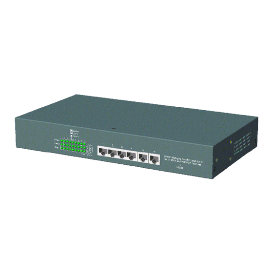
1. Introduction The switch provides six 10/100Mbps Fast Ethernet switched copper ports and two 100Mbps fiber port slots. The copper ports support auto-negotiation and auto MDI/MDI-X for easy making connections to Fast Ethernet devices. The switch also provides the following advantages: Fiber Connections The 100Mbps fiber port slots can accommodate a variety of optional fiber modules for multimode and single mode fiber connections. -
Page 7: Features
1.1 Features • Fast Ethernet switch with 6 10/100TX TP ports and 2 100FX slots • Auto MDI/MDI-X detection on all TP ports • Auto-negotiation capable on all TP ports • Port configuration control function • IEEE 802.3af PoE PSE function on 4 TP ports •... -
Page 8: Specifications
1.3 Specifications Network Ports TP Copper Ports 6 fixed 10/100TX Twisted Pair Ports (P1 - P6) PoE Function Ports 4 of the 6 10/100TX ports with configurable PoE PSE function (P1 - P4) FX Ports 2 100FX fiber slots 10/100TX Twisted Pair Port (TP Port P1 ~ P6) Compliance IEEE 802.3 10BASE-T, IEEE 802.3u 100BASE-TX Connectors... - Page 9 Control Enable/Disable via software control Monitor Power status, power voltage, power current, watts Switch Functions Forwarding & filtering Non-blocking, full wire speed Switching technology Store and forward Maximum packet length 1536 bytes Broadcast storm 64 consecutive broadcast packets in 800ms Protection by dropping broadcast storm packets VLAN function Port-based VLAN &...
- Page 10 Null VID replacement mode (Egress) QoS Function Priority level 2, High priority and Low priority Priority classifications Port-based priority mode (per port setting) 802.1p classification (per port setting) Default IP DSCP classification (per port setting) 2 user defined DSCP match classification (global) 2 user defined IP network address match classification (global) 802.1p priority tag Threshold tag value setting for high priority (0 ~ 7)
-
Page 11: Installation
2. Installation 2.1 Unpacking The product package contains: • The switch unit • One power cord • One 19-inch rack mounting kit • One product CD-ROM 2.2 Safety Cautions To reduce the risk of bodily injury, electrical shock, fire, and damage to the equipment, observe the following precautions. -
Page 12: Ac Power Supply
The steps to mount the switch onto a 19-inch rack are: 1. Turn the power to the switch off. 2. Install two brackets with supplied screws onto the switch as shown in above figure. 2. Mount the switch onto 19-inch rack with rack screws securely. 3. -
Page 13: Making Fiber Connections
3. The network cable used should meet the definition below: Straight Cat.5 PoE PSE RJ-45 end PoE PD RJ-45 MDI-X Pin 1 ------------------ Pin 1 Pin 2 ------------------ Pin 2 Pin 3 ------------------ Pin 3 Pin 4 ------------------ Pin 4 Pin 5 ------------------ Pin 5... -
Page 14: Configuring Ip Address And Access Settings For The Switch
2.8 Configuring IP Address and Access Settings for the Switch The switch is shipped with the following factory default settings: • IP address of the switch : 192.168.0.2 / 255.255.255.0 • User name : admin • Password : 123 For security reason, it is recommended to change the default settings for the switch before deploying it to your network. -
Page 15: Advanced Functions
3. Advanced Functions To help a better understanding about the software management interfaces, this chapter describes some advanced functions provided by the switch. 3.1 QoS Function The switch provides a powerful Quality of Service (QoS) function to guide the packet forwarding in two priority levels. -
Page 16: Port-Based Priority Setting (Per Port Setting)
3.1.3.1 Port-based Priority Setting (per port setting) As one port is configured to be enabled for port-based priority, all received packets on the port will be classified as high priority. The options are: Enable - All packets received on the port are classified as high priority Disable - Port-based classification is not applied. -
Page 17: Ip Network Address Classification
3.1.3.4 IP Network Address Classification User can configured two IP network address settings, IP(A) and IP(B). If a received IP packet’s source address or destination address belongs to the user defined IP network addresses. The packet is classified as high priority. User Defined IP(A) Classification (Global) Enable - Enable IP(A) checking... -
Page 18: Vlan Function
3.2 VLAN Function The switch supports port-based VLAN, 802.1Q Tag Aware VLAN and eight VLAN groups. Some VLAN related terminologies are described as follows: VLAN Group VLAN group specifies a VLAN information that can be referred by the switch in performing VLAN mapping and packet forwarding for ingress port and the received packets. -
Page 19: Ingress Rules
The following sections describe the VLAN processes and related settings provided by the switch. A global setting means the setting is applied to all ports of the switch. A per port setting means each port can be configured for the setting respectively. 3.2.2 Ingress Rules When a packet is received on an ingress port, the ingress rules are applied for packet filtering and mapping a VLAN group. -
Page 20: Vlan Group Mapping
3.2.3 VLAN Group Mapping The VLAN group mapping is the switch’s decision process to find a right VLAN group for the re- ceived packet when it is not filtered by ingress rules. The group mapping depends on the VLAN mode and the packet type. -
Page 21: Null Vid Replacement (Per Port Setting)
3.2.5.2 Null VID Replacement (per port setting) The null VID of a Null VID packet will be replaced with the associated ingress port’s PVID. This setting still works even Egress Tag rule : [PVID insertion for untagged packets only] is selected. 3.2.6 Summary of VLAN Function Number of VLAN groups : 8 groups at the same time VLAN ID supported : 1 ~ 4095 (12-bit VID) -
Page 22: Power Over Ethernet Function
3.3 Power over Ethernet Function Power over Ethernet (PoE) is a technology that DC power can be delivered over a twisted pair network cable to a remote connected device which has no other power supply input. The power is delivered together with bidirectional Ethernet network signals over the network cable. The advantage of the PoE technology is delivering power to a network device located in a place where power line is unable to reach. -
Page 23: Poe Management Functions
3.3.3.3 PoE Management functions The switch provides the following management function via software interfaces: 1. Enable or disable the switch’s PoE function. 2. Enable or disable port PoE function in per port basis. 3. Monitor the power up / down status on the PoE ports 4. -
Page 24: Software Management
4. Software Management The switch provides the following in-band management interfaces for configuring the switch to meet requirements for different applications: • Telnet over TCP/IP • Http web-based over TCP/IP • SNMP over TCP/IP 4.1 Telnet Management Interface Use Telnet software to perform the management operation. The most convenient solution is using the built-in Telnet function in your Windows PC. -
Page 25: Ip Menu
4.2 IP Menu Select [1] IP Menu to configure the switchs IP related settings. IP Menu: [0] Print this menu [1] Set IP Address [2] View IP status [Q] Back Menu Please Select(0-3)..INET>1 Enter Esc to abort.. Please Input IP Address(xxx.xxx.xxx.xxx):192.168.0.232 replacing net[0] IP address192.168.0.232 with 192.168.0.232 Please Input Subnet Mask(xxx.xxx.xxx.xxx):255.255.255.0 replacing subnet mask[0]255.255.255.0 with 255.255.255.0... -
Page 26: Snmp Menu
4.3 SNMP Menu This menu is used for configuring SNMP related settings. Snmp Menu: [0] Print this menu [1] View Snmp Setting [2] Set Snmp Name [3] Set Snmp Location [4] Set Snmp Contact [5] Set Snmp Community [6] Set Snmp Trap Manager [7] Set Port Link Trap Function [8] Set Login Failure Trap Function [Q] Back Menu... -
Page 27: Port Config
4.4 Port Config Select [3] Port Config to configure port configuration. Port Config Menu: [0] Print this menu [1] Port Status [2] Port Config [Q] Back Menu Please Select(0-3) Select [1] Port Status to view current port status for all ports as example below: INET>... -
Page 28: Administrator
100M - 100Mbps 10M - 10Mbps Duplex Control Duplex configuration when auto-negotiation is disabled Full - full duplex Half - half duplex Select [2] Port Config to view current port status for all ports as example below: Port Setting Description Ports Select port range to be configured. - Page 29 Select [1] VLAN Group Information to view all groups. VLAN Select: Disable VLAN Member Ports (O : member, - : not member): +---+---+---+---+---+---+---+---+---+ +---+---+---+---+---+---+---+---+---+ VLAN ID: Group +-------+----+----+----+----+----+----+----+----+ VLAN ID +-------+----+----+----+----+----+----+----+----+ INET> VLAN Information Description VLAN Select VLAN function of the switch is enabled or disabled. Member ports Table list for member ports : X axis - port number...
- Page 30 VLAN Global Settings Description 802.1Q Tag Aware Mode Enable - Under this mode, the switch will check the content of every received packets. For 802.1Q tagged packets, the tagged VID on the packet is used to look up the VLAN group table and find the group whose VID matches the packet tagged VID.
- Page 31 Select [6] VLAN Per Port Settings to configure VLAN ID for VLAN groups. VLAN Per Port Settings: Port Default Unmatched Egress Null Group tag rule +-----+--------+-----------+---------+---------+ Disabled Disabled Disabled Disabled Disabled Disabled Disabled Disabled Disabled Disabled Disabled Disabled Disabled Disabled Disabled Disabled +-----+--------+-----------+---------+---------+...
-
Page 32: Administrator -> Qos Settings
Null VID The null VID of a Null VID packet will be replaced with the associated ingress port’s PVID. This setting still works even Egress Tag rule : [PVID insertion for untagged packets only] is selected. Enable - Null VID is replaced with Port’s PVID for Null VID packets Disable - Null VID replacement rule is not applied. - Page 33 AF - <001010> <010010> <011010> <100010> and Network Control - <111000> <110000> Disable - Default DSCP classification is not applied. Select [2] QoS Other Settings to configure QoS global settings: QoS Other Settings: [0] Print this menu [1] Show QoS Other Status [2] 802.1p priority tag [3] Egress service policy [4] Specific DS Settings...
- Page 34 Specific IP(A) Setting If a received IP packet’s source address or destination address belongs to the user defined IP network addresses. The packet is classified as high priority. Enable - Enable user defined IP(A) network address checking Disable - IP(A) classification is not applied. Specific IP(A) Value Set user defined IP(A) address for classification.
-
Page 35: Administrator -> Poe Settings
4.5.3 Administrator -> PoE Settings Select [4] Administrator -> [3] PoE Settings to configure PoE function related settings: PoE Settings: [0] Print this menu [1] PoE Status [2] PoE Master Enable [3] PoE Port Enable [Q] Back Administrator Please Select(0-4)..INET>... -
Page 36: Restore Default Values
4.6 Restore Default Values Select [6] Restore Default Values to restore all settings of the switch back to factory default values. Do you want to restore system default settings?(Y/N): Refer to Appendix for factory default values. 4.7 Security Manager Select [7] Security Manager to change user name and password. The user name and password are used for login into the switch in telnet management and web management. -
Page 37: Reboot System
Setting Description TFTP IP Address IP address of the TFTP server from where a new firmware is down- loaded. 4.9 Reboot System Select [7] Reboot System to reboot the switch. Do you want to reboot system ?(Y/N):y Start rebooting..Press [Y] to confirm to reboot the switch with current configuration settings. Note that the current telnet connection will be disconnected after confirmation. -
Page 38: Web Management
5. Web Management The switch features an http server which can serve the management requests coming from any web browser software over internet or intranet network. Web Browser Compatible web browser software with JAVA support Microsoft Internet Explorer 4.0 or later Netscape Communicator 4.x or later Set IP Address for the System Unit Before the switch can be managed from a web browser software, make sure a unique IP address is... - Page 39 The following screen shows welcome screen when a successful login is performed. In addition to the device image, the screen supports the following menus on the right side: 1. Home : home page and device image 2. Port Status : view all switched port status 3.
-
Page 40: Port Status Menu
5.3 Port Status Menu Click >Port Status Menu to display the port status for all switched ports. The pop-up port status list is as follows: Port Status Description Port Number 1 - 6 : 10/100TX ports - P1 ~ P2 7 - 8 : 100FX ports - F1 F2 Link Status Port link status... -
Page 41: Administrator
5.4 Administrator Click >Administrator to perform more advanced management functions as follows: Menu Function Basic Configure IP and SNMP settings for the switch Port Control Change port configuration including auto-negotiation, speed, duplex VLAN Controls Configure VLAN related settings QoS Controls Configure QoS related settings PoE Controls Configure Power over Ethernet (PoE) settings... - Page 42 IP Address IP Address Setting Description IP Address IP address for the switch Submask Subnet mask of the IP address Gateway IP address of the default gateway SNMP Entries SNMP settings include system settings, community settings and Snmp trap settings as follows: System Settings Description Name Set a system name for the switch...
- Page 43 Community Settings Description Community String Community strings which are allowed to access the switch unit via SNMP protocol Access Right The access right assigned to the community string, options are: RO - read only RW - read / write <<Add>> Add one new community string specified in String box.
-
Page 44: Port Controls
changes Enable Login Failure Trap Button to enable the switch to send a trap when any login failure is detected 5.4.2 Port Controls Port Settings Description Port Specify the ports for the new settings. More than one port can be configured at the same time. Use <Shift> key and <Ctrl>... -
Page 45: Vlan Controls
5.4.3 VLAN Controls VLAN settings are divided into three categories: 1. Global - Settings which are applied for the switch and not for specific ports 2. Group - Settings for VLAN groups 3. Per Port - Settings applied to each port Global Settings Description VLAN... - Page 46 VLAN Group Configuration Group Settings Description Groups Specify the VLAN group for member port configuration Port Specify the port to be added into or deleted from the specified group. Null - unchanged Add - add the port into member port list of the group Del - delete the port from member list of the group Apply Button to confirm the settings...
- Page 47 Per Port Settings Per Port Settings Description Port Select port list for configuration. Ingress Rules Default Group Index to the default VLAN group of the selected ports, group 1 ~ 8 Unmatched VID Null - unchanged Enable - Drop the tagged packet if the packet VID does not match the ingress port PVID Disable - No Unmatched VID filtering is applied to the port Egress Rules...
-
Page 48: Qos Controls
Tagged packet : the packet is not modified 4 No tag insertion and tag removal - The packet is not modified at all. No tag insertion or tag removal are performed for all packets. Null VID The null VID of a Null VID packet will be replaced with the associated ingress port’s PVID. - Page 49 below, the packet is classified as high priority. EF - <101110>, AF - <001010> <010010> <011010> <100010> and Network Control - <111000> <110000> Disable - Default DSCP classification is not applied. Apply Button to confirm settings. QoS Global Settings Description 802.1p high priority threshold 802.1p High Priority Tag Setting for 802.1p classification Valid values : 0 - 7...
- Page 50 IP network address for IP packet classification. Specific IP & Mask (B) If a received IP packet’s source address or destination address belongs to the user defined IP network addresses. The packet is classified as high priority. Enable - Enable user defined IP(B) network address checking Disable - IP(B) classification is not applied.
-
Page 51: Poe Controls
5.4.5 PoE Controls PoE Controls menu is sued to configure the settings for PoE function as follows: PoE Settings Description Master Enable Activate PoE function of the switch Enable - enable PoE function for the switch Disable - disable PoE function for the switch Port Select port list for Port PoE Enable setting Port PoE Enable... -
Page 52: Security Manager
5.4.6 Security Manager This menu is used to change the user name and password. User name and password are used for access login in telnet and web management interfaces of the switch. Settings Description User Name New user name Assign/Change password New password Reconfirm password Retype the new password... -
Page 53: Update Firmware
5.4.8 Update Firmware This menu is used to perform firmware (switch software) upgrade via TFTP protocol. Before doing TFTP operation, one TFTP server must be available in the network to where this switch is connected and the new firmware file is placed in the server. -
Page 54: Snmp Management
6. SNMP Management The switch supports SNMP v1 protocol for SNMP management. One device MIB file is provided in the product CD. The MIB file is used for SNMP management software to set or get the management information objects provided in the switch. 6.1 MIB Objects The device private management objects provided by the SNMP agent in the switch are: Objects... -
Page 55: Appendix. Factory Default Settings
Appendix. Factory Default Settings IP Settings IP Address 192.168.0.2 IP Subnet mask 255.255.255.0 Gateway IP 192.168.0.1 Security Manager Settings User name admin Password SNMP Settings System name Null System location Null System contact Null Community string 1 Public, Access right - read only Community string 2-4 Null Trap manager 1-3 IP... - Page 56 VLAN group 6 member : P6, VID : 6 VLAN group 7 member : P7, VID : 7 VLAN group 8 member : P8, VID : 8 Default VLAN group index 1 (group 1) for Port 1 - Port 8 Unmatched VID Disabled for Port 1 - Port 8 Egress tag rule...
Need help?
Do you have a question about the KS-1080 and is the answer not in the manual?
Questions and answers