Table of Contents
Advertisement
Quick Links
tu rb ochef t ec hnologie s, inc.
ngo rev e service Manual changes
May 2010
Upper jetplate part number now i1-3204
Added i1-9179 support rails to appendix
Added NGC-1194 switch offset shim (x2)
i1-9029 (SOTA) / i1-9023 (NGO)
SOTA letters: i1-9052 = S, i1-9053 = O,
i1-9054 = T, i1-9055 = A, i1-9056 = Caret
Left ctl: i1-9057 (SOTA) / i1-9453 (SBK)
Right ctl: i1-9058 (SOTA) / i1-9452 (SBK)
Door cover: i1-9109 (SOTA) / i1-9444 (SBK)
Shell: i1-9240 (SOTA) / i1-9445 (SBK)
Medallion: i1-9491 (SOTA) / i1-9489 (SBK)
LED light ring: i1-9198
Front panel: i1-9246 (SOTA) / i1-9458 (SBK)
Keypad: i1-9451-1 (SOTA) / i1-9451-2 (SBK)
i1-3201 = NGO SBK Door Kit
Added LED light ring to "controls" section
Specified "gray" smart card
Various appendix drawing updates
Add to safety instrutions: DO NOT cook with
metal lids or aluminum foil
Add to safety instrutions: DO NOT cook
without food in the cook cavity
Specified i1-3202 waveguide kit
Specified i1-3207 switch paddle kit
Removed blower component (hub, wheel, heat
slinger) part numbers, changed to REF
Appendix housekeeping
Updated door detail and part numbers
Removed blower assembly detail
Specified stirrer blade kit i1-3208
Changed coupling part number from 104134
to 104306
© 2009-2010 turbochef technologies, inc.
Updated stirrer motor detail
Changed motor controller part number from
100446 to CON-7039
Added international component part numbers
Added i1-3210 shunt plate kit
Added note about how to apply a new keypad
Added note to not apply push nut to trim
prong, to prevent interference with display
Added section: Troubleshooting: Menu settings
are not present
Moved "Write fail" troubleshooting to page 42
Updated schematic
Specified NGC-3033 for primary switch
replacement and modified drawing
Added notes for replacing primary switch
Specified stirrer shaft kit i1-3209
Added verbiage to cleaning instructions about
not forcing the rack out by pulling upward
Advertisement
Table of Contents
Troubleshooting

Related Manuals for TurboChef NGO/SOTA


Summary of Contents for TurboChef NGO/SOTA
- Page 1 REF Appendix housekeeping Updated door detail and part numbers Removed blower assembly detail Specified stirrer blade kit i1-3208 Changed coupling part number from 104134 to 104306 © 2009-2010 turbochef technologies, inc.
- Page 2 Service Manual F O R T H E T U R B O C H E F N G O S O TA R A P I D C O O K O V E N ©2009-2010 TurboChef Technologies, Inc.
- Page 4 For further information, call 800.90TURBO +1 214.379.6000...
- Page 5 The information contained in this manual is important for the proper installation, use, maintenance, and repair of this oven. Follow these procedures and instructions to help ensure satisfactory baking results and years of trouble-free service. Errors – descriptive, typographic, or pictorial – are subject to correction. Specifications are subject to change without notice.
-
Page 6: Table Of Contents
Table of Contents Safety Instructions General Safety Information Reducing Fire Risk Grounding Instructions Power Cord Replacement Precautions to be Observed Before and During Servicing to Avoid Possible Exposure to Excessive Microwave Energy RF Interference Considerations Specifications and Installation Theory of Operation Dimensions Certifications Oven Construction... - Page 7 Info, Test, and Edit Mode Overview of the Info Mode Viewing Cook Counter/Time Logs Viewing the Fault Log Viewing the Service Numbers Setting the Language Resetting the Oven Set Options Screen Network Setup Auto On and Off: Setting the Time Test Mode - Testing Oven Parts Status Indicators Turning Diagnostic Mode On/Off...
- Page 8 Microwave System Capacitors Testing a Capacitor Filament Transformers Wiring the Filament Transformers High-Voltage Transformers Wiring the High-Voltage Transformers Testing a Filament or High-Voltage Transformer High-Voltage Diodes Testing a High-Voltage Diode Magnetrons Testing a Magnetron for an Open/Shorted Filament Stirrer Motor and Assembly Waveguides Troubleshooting Control System...
- Page 9 Troubleshooting Overview of Troubleshooting Fault Code Descriptions Fault Code Troubleshooting - F1 Blower Running Status Bad Fault Code Troubleshooting - F2 Cook Temperature Low Fault Code Troubleshooting - F3 Magnetron Current Low Fault Code Troubleshooting - F4 Door Monitor Defective Fault Code Troubleshooting - F5 Magnetron Over Temperature Fault Code Troubleshooting - F6 Electrical Compartment Temperature High Fault Code Troubleshooting - F7 RTD Open...
-
Page 10: Important Safety Instructions
IMPORTANT SAFETY INSTRUCTIONS WARNING: When operating this oven, strictly adhere to the following safety precautions to reduce the risk of burns, electric shock, fire, injury, damage to oven or property near oven, or possible exposure to excessive microwave energy. General Safety Information Read all instructions before using this appliance. -
Page 11: Safety Instructions
SAFETY INSTRUCTIONS Grounding Instructions This appliance must be grounded. In the event of an electrical short circuit, grounding reduces the risk of electric shock by providing an escape wire for the electric current. This oven is equipped with a cord that has a grounding wire with a grounding plug, which must be plugged into an outlet that is properly installed and grounded. -
Page 12: Specifications And Installation
Specifications and Installation... -
Page 14: Theory Of Operation
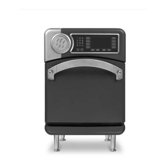
4.2” (107 mm) Figure 1: NGO Oven Dimensions Theory of Operation Dimensions Utilizing TurboChef ’s patented technology to Oven Dimensions rapidly cook food without compromising quality, Height: 25.0” (635 mm) the NGO oven provides superior cooking Width: 16.0” (406 mm) performance while requiring minimal space and Depth (footprint): 18.5”... -
Page 15: Certifications
Brazil (BK): 220 VAC, 60 Hz, 28 A TurboChef will not recognize a fallen oven as Latin America (LA): 220 VAC, 60 Hz, 28 A a warrantable claim and is not liable for any... -
Page 16: Lifting And Placing The Oven
Installation Near Open Heat Source 1. Prepare a surface at least 26” (660 mm) deep When placing a TurboChef oven near an open heat and capable of supporting 175 lb. (79 kg). source (Figure 2), strictly adhere to the following:... -
Page 17: Oven Connect Suite
Part Number: CON-7006 240 VAC ChefComm Pro® empowers any user of a TurboChef oven to easily create menu settings on a computer and transfer them to an oven via smart Figure 3: Selecting Voltage card. For more information, call TurboChef Customer Support at 800.90TURBO or... -
Page 18: Daily Maintenance
Daily Maintenance... - Page 20 • Detach the wire rack from the jetplate and wash, rinse, sanitize, and dry each part. Step 4: Clean the Air Filter CAUTION: TurboChef does not recognize blocked air vents as a warrantable claim. The filter must be cleaned regularly or replaced if damaged. During oven Step 4 operation, the filter must remain in place at all times.
- Page 21 DAILY MAINTENANCE Step 6: Clean the Oven Interior • Spray TurboChef ® Oven Cleaner onto the top, bottom, and sides of oven interior. CAUTION: DO NOT spray Oven Cleaner into the holes on the back oven wall. Doing so can damage critical oven components, resulting in a non- warranty service call.
-
Page 22: Oven Controls And Cooking
Oven Controls and Cooking... -
Page 24: Oven Controls
Figure 4: Oven Controls When the oven is ready to cook (i.e., warmed up Oven Controls and waiting for a cook command), or in the Info Mode (page 11), press the Back/Stop key to return 1. On/Off Key to the previous screen. Press to turn the oven on (begin warmup) or off (cool down), or to exit Info Mode (page 11). -
Page 25: Cooking
(Step 10). Step 1: Turn the Oven On When the oven is off (Figure 5), the oven temperature has receded below 150°F (66°C), but the display and keypad TURBOCHEF NGO OVEN OFF remain on. RE ADY TO CLEA N Press the On/Off key to turn the oven on. -
Page 26: Step 4: Soaking
Step 4: Soaking Once the oven temperature reaches the set point, the oven will continue to warm for eight minutes to ensure the cook cavity surfaces absorb enough heat so as to not affect cooking results. This process is called “soaking.” NOTE: While the oven is soaking, the operator will be able to navigate through the menu, but will not be allowed to cook until the timer reaches 0:00. -
Page 27: Step 8: Check/Remove Food From Oven
OVEN CONTROLS AND COOKING Step 8: Check/Remove Food from Oven WARNING: Dish and inside of oven/oven door are hot! WA RM ING DONE P L EA SE CH ECK F OOD Open the oven door and check/remove food. Figure 10: Cooking Done Step 9: Additional Cooking Options The Additional Cooking Options screen (Figure 11) is A DDI TI O NA L COOK ING OP T IO NS... -
Page 28: Info, Test, And Edit Mode
Info, Test, and Edit Mode... -
Page 30: Overview Of The Info Mode
Overview of the Info Mode Viewing Cook Counter/Time Logs From Screen 1 of the Info Mode (Figure 12), press To access the Info Mode, press the Info key when the the R1 soft key (Counts Scroll): oven is either off or cooling down. To toggle between - Once to display the cook counter. -
Page 31: Set Options Screen
Daylight Savings Time. - Auto On/Off NOTE: The clock is 24-hour (8:30 p.m. = 20:30). - Demo Mode (TurboChef use only) NOTE: The oven will not retain the date and time if Network Setup it is left unplugged for two or more weeks. -
Page 32: Test Mode - Testing Oven Parts
3. To navigate between digits, use the L3 and R3 Stirrer soft keys for auto-on time and the L4 and R4 Press the R1 soft key (Figure 16) to turn the stirrer soft keys for auto-off time. on/off. 4. Use the number keys to enter the desired hour and minute for the oven to automatically turn Status Indicators on or off. -
Page 33: Manufacturing Mode
PASS or FAIL. ensure all cavity walls reach thermal equilibrium before testing is conducted. Burn in should not be initiated in the field unless instructed by TurboChef. MA NUFAC TU RIN G MOD E MA NUFAC TU RIN G MOD E... -
Page 34: Volt On
Volt On This setting should not be changed in the field unless instructed by TurboChef. Press the R2 soft key (Figure 17, page 14) to enable/disable the voltage from displaying in Info Mode. Typically, this setting is disabled for ovens installed outside the United States. -
Page 35: Updating The Oven Menu
If the update fails multiple times, may need to verify that access to the Load Menu contact TurboChef as a card may be damaged. screen is turned on. See the Set Options Screen section on page 12 for more details. -
Page 36: Overview Of The Edit Mode
2. Press the On/Off key to return the oven to the your menu developer, authorized distributor, or “Cooling Down” or “Off ” screen. TurboChef Customer Support. 3. Press the On/Off key again to enter Edit Mode. To change a set temperature, The Edit Mode serves three main purposes: 1. -
Page 37: Changing Group/Item/Quantity Name
INFO, TEST, AND EDIT MODE Editing Recipe Settings Changing Group/Item/Quantity Name Changing Cook Settings To change a food group, item, or quantity name: To change cook settings, 1. Place the oven in Edit Mode (see page 17). 1. Follow the steps in Changing Group/Item/ 2. -
Page 38: Oven Systems
Oven Systems... -
Page 40: Convection System
Heater Elements Convection System The main convection heaters are sheathed-style The convection system is designed to rapidly heat, and rated at 3000 watts at 208 VAC, with a clean, and recirculate air into the cook cavity. resistance of 14.4 Ohms. The convection heaters This section contains information about the are controlled by the K4/K5 solid state relay, and following components:... -
Page 41: Oven Door
OVEN SYSTEMS 7. From Test Mode, check the status indicators Oven Door “P” “S” and “M” to verify the switches engage This section contains information about the (door closed) and disengage (door open) following components: properly. If they do not, adjust the switches - Oven door per the instructions on page 21. -
Page 42: Interlock Switches
NOTE: Do not push one end at a time, which 1. Ensure the oven has been at operating temperature could cause the opposite end to lift away from for at least fifteen minutes. the flange. 2. If adjusting the primary switch, confirm the primary switch’s latch toggle is in the correct 3. -
Page 43: Measuring Rf Leakage For Microwave Safety
OVEN SYSTEMS 7. As microwave leakage is observed while moving Measuring RF Leakage for Microwave Safety the sensor, note any meter spike areas that come WARNING: This procedure requires work with close to 5mW/cm for later re-measurement. hot surfaces and water loads. To avoid burns, be 8. -
Page 44: Microwave System
1. Disconnect the oven from the power source. Microwave System 2. Fully discharge the capacitor. The NGO oven employs left and right microwave 3. Isolate the capacitor from the circuit. systems. In the case of an over-current situation, 4. Check for an open or shorted capacitor by the F3 fuse will blow, shutting off both systems placing ohmmeter leads between the capacitor immediately. -
Page 45: High-Voltage Transformers
OVEN SYSTEMS High-Voltage Transformers Testing a Filament or High-Voltage Transformer High-voltage transformers are ferro-resonant, which DANGER: Never attempt to measure the limits faulty currents and minimizes magnetron power secondary voltage values of the HV changes due to input voltage changes. The high- transformers. -
Page 46: Testing A High-Voltage Diode
High Voltage Transformers Primary Voltage, Frequency, Taps, Secondary Taps and Resistance and Resistance NGC-3062-1 208 VAC, 60 Hz, 1 & 2, 4, Ground, 53.60–65.52 0.819–1.001 240 VAC, 60 Hz, 1 & 3, 0.972–1.188 NGC-3062-2 230 VAC, 50 Hz, 1 & 2, 3, Ground, 57.52–70.30 0.972–1.188 Filament Transformers... -
Page 47: Magnetrons
OVEN SYSTEMS 3. An ohmmeter connected between the filament Magnetrons terminals (F, FA) should indicate a reading of less Figure 33. Magnetrons supply the RF energy at 2.45 than 1 ohm. Figure 33. GHz and begin to oscillate when they are supplied 4. -
Page 48: Control System
If the control board is damaged to the point of not Control System allowing access to the Network Setup screen, have This section contains information about the the store contact its Oven Connect administrator following components: to obtain the proper network settings. - Control board - Cooling fans Cooling Fans... -
Page 49: Ethernet Extension Cable
OVEN SYSTEMS Ethernet Extension Cable Magnetron Thermostats The ethernet extension cable exits the oven at the The magnetron thermostats are “open-on rise.” They are designed to open at 270 º F (132 º C), back panel and allows the oven to be connected to a local network, in case the customer desires remote which triggers an F5 fault. -
Page 50: Relay - K7 Monitor
Relay - K7 Monitor Solid State Relay - K4/K5 Heater The K7 relay is a 240 VAC, 30 amp, double-pole, The solid state relay is a 240 VAC, dual 40-amp double-throw, 24 VDC relay coil. It shorts L1 and relay. K4 switches power to heater one, and K5 L2 if the monitor switch opens before the primary switches power to heater two. -
Page 51: Filtering System
- Undesirable flavor transfer. - Undesirable odor emissions. CAUTION: Clean the catalytic converter with TurboChef Oven Cleaner and rinse thoroughly with distilled water. Let the catalytic converter air dry before reinstalling. If TurboChef Oven Cleaner is not available, use only distilled water. -
Page 52: Troubleshooting
Troubleshooting... -
Page 54: Overview Of Troubleshooting
Overview of Troubleshooting F3: Magnetron Current Low This fault is displayed when the current trans- This section contains information on the former (CT) on the I/O control board detects less following: than 10 amps. The fault is monitored when the - Fault code descriptions microwave is on during a cook cycle or in Test - Fault code troubleshooting... - Page 55 TROUBLESHOOTING F7: RTD Open F9: Cook Cavity Temperature High This fault is displayed when the control detects This fault will signal that the catalyst has “flashed” that the RTD is “open.” The display will show a due to excessive grease. The fault occurs when the reading of “999 º...
-
Page 56: Fault Code Troubleshooting
Fault Code Troubleshooting From Test Mode, you can run oven diagnostics and check fault counts. To access Test Mode or turn on Diagnostic mode, see page 13. To locate oven components for testing, adjustment, or replacement, see the Appendix. Troubleshooting: F1: BLOWER (Blower Running Status Bad) Do resistance measurements Remove obstruc-... - Page 57 TROUBLESHOOTING Troubleshooting: F2: LOW TMP (Cook Temperature Low) Is either of the heater ele- Reset (Figure 34, page 28) Is the high-limit ments defective? (heaters and determine why it thermostat tripped? should have a resistance of tripped – excess grease 14.4 Ohms) buildup, etc.
- Page 58 Troubleshooting: F3: MAG CURR (Magnetron Current Low) Is the K6 mechanical Energize the mag- relay in good working U.S. Intl. netron circuit from Is the oven International or U.S.? order? Test Mode (page 13). Are there 10+ amps present on the current Confirm the F3 fuse is a Replace the F3 fuse and Replace K6...
- Page 59 TROUBLESHOOTING Troubleshooting: F4: MONITOR (Door Monitor Defective) Is the F3 fuse blown? Replace the F3 fuse. Are the switches opening in the correct sequence (P, S, M) while the oven is hot? (Ensure the Adjust the monitor safety switch. oven has been at operating See page 21 for instructions.
- Page 60 Troubleshooting: F6: EC TEMP (Electrical Compartment Temperature High) Is the oven in an area of moderate temperature (120ºF [49ºC] or cooler)? Does the oven have Relocate oven to room to ventilate? cooler area. Move oven to open area or remove Required clearances: items that are in close proximity.
- Page 61 TROUBLESHOOTING Troubleshooting: F8: HEAT LOW Are both blower motors moving air? Check in Test Mode - see page 13. Is the high-limit Are either of the heaters defective? See page 33 thermostat tripped? Check in Test Mode - see page 13. to troubleshoot F1: BLOWER (Blower Running...
- Page 62 Non-Fault Code Troubleshooting This section provides troubleshooting tips for issues that may occur independently of an oven fault. Troubleshooting: No Keypad Input Is the keypad cable properly connected to the control board? Correct wiring. Replace the keypad. If the problem persists, replace the control board.
- Page 63 TROUBLESHOOTING Troubleshooting: No Display – Screen is Blank Does the keypad beep when a key is pressed? Is the power supply Replace the F1 and/or receiving power? the F2 fuse. Is wiring from the Correct wiring. If control board to the ribbon cable is display OK? damaged, replace the...
- Page 64 Is the menu part number and Ensure the food item revision correct? Verify with is being properly customer or contact stored/prepared TurboChef Customer Service. before cooking. Is the correct amount of food (portion) Contact Customer being cooked? Service to obtain the correct menu and load it to the oven.
- Page 65 Does a backup copy of No backup copy smart card reader to the menu work? control board OK? If the menu card was created by TurboChef, Ensure the cable obtain a new menu card Replace the card connecting the reader to by contacting customer...
- Page 66 Troubleshooting: Menu Settings are Not Present Try loading a menu from a new smart card, ensuring the smart card is the correct type (gray for SBK ovens and white for SOTA ovens). Was the load successful? Perform a firmware update, following the instructions on page 16, then load the menu card again.
-
Page 67: Plugged In Or Restarted
TROUBLESHOOTING Troubleshooting: “Defective Media” Message When Oven is Plugged in or Restarted Does the message prevent the oven from reaching the “Oven Off/ Cooling Down” screen? Unplug the oven and Operate the oven as then plug it back in. you would normally. Did this fix the problem? Perform a microwave leak-... -
Page 68: Oven Schematic
Oven Schematic... - Page 70 REAR COOLING FANS TURBOCHEF TECHNICAL SUPPORT QC-11 RELEASE FOR PRODUCTION ECN # 0909016 9/09/09 D CASTILLO 800.908.8726 (USA) K3 (STIRRER) DELTA CONFIG. ADDITION, GENERAL P/N UPDATES ECN # 1001003 D CASTILLO +214.379.6000 (INTERNATIONAL) 1/7/10 MAGNETRON OVERTEMP 100516 280 F ( 132 C)
- Page 71 OVEN SCHEMATIC This page intentionally left blank.
-
Page 72: Appendix - Replacing Oven Components
Appendix - Replacing Oven Components... -
Page 74: Replacing Oven Components
- Removing Outer Shell Required (pages A-4 through A-10) - Removing Outer Shell and Back Cover Required (page A-11) If you have any questions that are not addressed in this manual or appendix, please contact TurboChef Customer Service at 800.90TURBO or +1 214.379.6000. -
Page 75: Replacing Items - No Cover Removal Required
APPENDIX - REPLACING OVEN COMPONENTS Replacing Items - No Cover Removal Required (Figures A-1 through A-2) CAUTION: Before removing/installing any component, make sure it is disconnected from the wire harness (where applicable). NOTE: Hardware listed is required for installing component to oven. 19 x4 See Figure A-2 for details... - Page 76 Figure Item Description Item Part Number Hardware Description Hardware Part Number(s) Reference # Actuator, Door Latch NGC-1076-2 Screw, Torx w/ Post, Sht Mtl, .50 Lg, Blk Ox 102756 (qty 2) i1-9240 (SOTA) Screw, #8 x 1/2, Serr Ph Truss Hd, Bk Oxide 101691 (qty 6) Cover, Outer Shell i1-9445 (SBK)
-
Page 77: Replacing Items - Removing Outer Shell Required
APPENDIX - REPLACING OVEN COMPONENTS Replacing Items - Removing Outer Shell Required (Figures A-3 through A-12) DANGER: Before replacing any oven component, ensure the oven is removed from any power source. Replacing a component while the oven is plugged in can result in serious injury or death CAUTION: Be careful to not tear the insulation when servicing components. - Page 78 Figure Hardware Part Item Description Item Part Number Hardware Description Reference # Number(s) Blower Motor, Bottom i3-9042 Nut, 1/4 - 20, Serr Hex Flange, Plated 100906 (qty 4) Blower Motor, Top i3-9040 Nut, 1/4 - 20, Serr Hex Flange, Plated 100906 (qty 4) Cable, Ethernet, Ext, 3’...
- Page 79 APPENDIX - REPLACING OVEN COMPONENTS See Figure A-8 for Waveguide Detail See Figs A-5 and A-6 Figure A-7: Outer Shell Removed (Top View) and Stirrer Motor Detail...
- Page 80 Figure Item Description Item Part Number Hardware Description Hardware Part Number(s) Reference # Bracket, Mounting, Mag Fan (x2) i1-9478 Screw, #8 x 1/2, Serr Ph Truss Hd, Sheet Mtl 101688 (qty 2 each) 100543 (1 Ph) EMI Filter Screw, #8 x 1/2, Serr Ph Truss Hd, Sheet Mtl 101688 (qty 4) 100547 (3 Ph) Fuses, F1 and F2, 12-amp 100592...
- Page 81 APPENDIX - REPLACING OVEN COMPONENTS Figure Item Description Item Part Number Hardware Description Hardware Part Number(s) Reference # Kit, Door Switch, Primary* NGC-3033* Included Included Hinge, LHS 102825 Screw, #8-32 x 5/8, PFH, 100 Deg, SS 102811 (qty 3) Hinge, RHS 102826 Screw, #8-32 x 5/8, PFH, 100 Deg, SS 102811 (qty 3)
- Page 82 Figure A-10: Left Hinge / Secondary Switch Detail Figure A-11: Right Hinge / Monitor Switch Detail...
- Page 83 A-10 APPENDIX - REPLACING OVEN COMPONENTS 72 73 To prevent interference with display, do not apply push nut to this prong. Figure A-12: Outer Shell Removed - Control Panel Figure Item Description Item Part Number Hardware Description Hardware Part Number(s) Reference # Cable, Display, Power, 3-Pin, 3-Wire i1-9475 None...
-
Page 84: Replacing Items - Removing Outer Shell And Back Cover Required
A-11 Replacing Items - Removing Outer Shell and Back Cover Required (Figure A-13) DANGER: Before replacing any oven component, ensure the oven is removed from any power source. Replacing a component while the oven is plugged in can result in serious injury or death. CAUTION: Be careful to not tear the insulation when servicing components. - Page 85 For service or information: W I T H I N N O RT H A M E R I C A C A L L Customer Support at 800.90 TURBO O U T S I D E N O RT H A M E R I C A C A L L +1 214.379.6000 or Your Authorized Distributor Global Operations Customer Support:...
Need help?
Do you have a question about the NGO/SOTA and is the answer not in the manual?
Questions and answers