Table of Contents
Advertisement
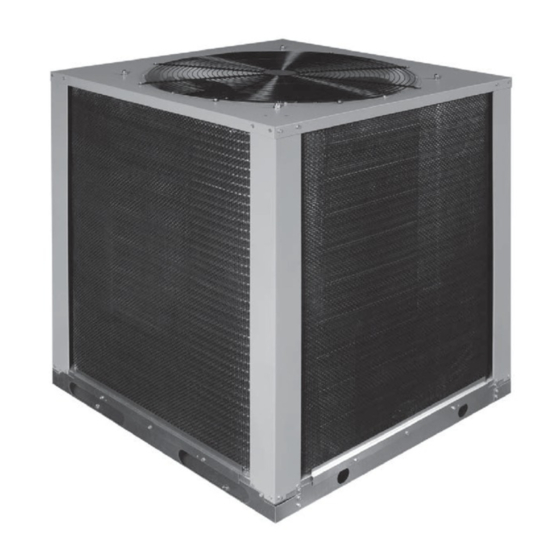
SPLIT SYSTEM HEAT PUMP WITH MICROCHANNEL COILS
INSTALLATION INSTRUCTIONS
T4BE - 018, 024, 030, 036, 042, 048, & 060 (1.5, 2, 2.5, 3, 3.5, 4, & 5 TON) SERIES
SINGLE PHASE MODELS
IMPORTANT SAFETY INFORMATION ............................ 2
HEAT PUMP INSTALLATION ........................................... 3
General Information ......................................................... 3
Before You Install the Heat Pump ................................... 3
Locating the Heat Pump .................................................. 3
Packaging Removal ......................................................... 3
Ground Level ................................................................... 3
Rooftop ............................................................................ 3
Outdoor Unit .................................................................... 4
Outdoor Orifice Removal & Installation ........................... 4
ELECTRICAL WIRING ...................................................... 5
Pre-Electrical Checklist ................................................... 5
Line Voltage ..................................................................... 5
Grounding ........................................................................ 6
Thermostat / Low Voltage Connections .......................... 6
Diagnostics Module ................................... 6
Compressor Protection .................................................. 7
Resetting Alert Codes ................................................... 7
START UP & ADJUSTMENTS ......................................... 7
Pre-Start Check List ........................................................ 7
Start-Up Procedures ........................................................ 7
Air Circulation - Indoor Blower ......................................... 7
Short Cycle Protection ..................................................... 8
System Cooling ............................................................... 8
System Heating ............................................................... 8
Defrost Control Board Test Pins ...................................... 8
HEAT PUMP MAINTENANCE .......................................... 8
It is your responsibility to know this product better than your customer. This includes being able to install the product
according to strict safety guidelines and instructing the customer on how to operate and maintain the equipment for
the life of the product. Safety should always be the deciding factor when installing this product and using common
sense plays an important role as well. Pay attention to all safety warnings and any other special notes highlighted
in the manual. Improper installation of the furnace or failure to follow safety warnings could result in serious injury,
death, or property damage.
These instructions are primarily intended to assist qualified individuals experienced in the proper installation of this
appliance. Some local codes require licensed installation/service personnel for this type of equipment. Please read all
instructions carefully before starting the installation. Return these instructions to the customer's package for future
reference.
DO NOT DESTROY. PLEASE READ CAREFULLY & KEEP IN A SAFE PLACE FOR FUTURE REFERENCE.
REFRIGERANT CHARGING ............................................ 9
Charging the Unit in AC Mode ......................................... 9
(Cooling Mode Only) ....................................................... 10
Figure 6. Charging Chart for 1.5 Ton Models ................. 10
Figure 7. Charging Chart for 2 Ton Models .................... 11
Figure 8. Charging Chart for 2.5 Ton Models ................. 11
Figure 9. Charging Chart for 3 Ton Models .................... 12
Figure 10. Charging Chart for 3.5 Ton Models ............... 12
Figure 11. Charging Chart for 4 Ton Models .................. 13
Figure 12. Charging Chart for 5 Ton Models .................. 13
Refrigerant Charging Tables (Cooling Mode Only) ......... 14
Table 5. Charging Table for 1.5 Ton Models ................... 14
Table 6. Charging Table for 2 Ton Models ...................... 14
Table 7. Charging Table for 2.5 Ton Models ................... 15
Table 8. Charging Table for 3 Ton Models ...................... 15
Table 9. Charging Table for 3.5 Ton Models ................... 16
Table 10. Charging Table for 4 Ton Models .................... 16
Table 11. Charging Table for 5 Ton Models .................... 17
(Heat Mode Only) ............................................................ 18
Table 12. Verification Table for 1.5 Ton Models .............. 19
Table 13. Verification Table for 2 Ton Models ................. 19
Table 14. Verification Table for 2.5 Ton Models .............. 19
Table 15. Verification Table for 3 Ton Models ................. 19
Table 16. Verification Table for 3.5 Ton Models .............. 20
Table 17. Verification Table for 4 Ton Models ................. 20
Table 18. Verification Table for 5 Ton Models ................. 20
WIRING DIAGRAMS ......................................................... 21
Figure 13. W.D. for 1.5 - 5 Ton Models Equipped With
Figure 14. W.D. for 1.5 - 5 Ton Models NOT Equipped
Figure 15. W.D. for 1.5 - 5 Ton Models Equipped with
INSTALLATION / PERFORMANCE CHECK LIST ........... 24
REPLACEMENT PARTS ................................................... 24
IMPORTANT
ATTENTION INSTALLERS:
CoreSense
Diagnostic Module ................... 21
TM
With CoreSense
Diagnostic Module .......... 22
Low Pressure Switch .................................... 23
14 SEER
Advertisement
Table of Contents

Subscribe to Our Youtube Channel
Related Manuals for Nordyne T4BE-018 Series


Summary of Contents for Nordyne T4BE-018 Series
-
Page 1: Table Of Contents
SPLIT SYSTEM HEAT PUMP WITH MICROCHANNEL COILS 14 SEER INSTALLATION INSTRUCTIONS T4BE - 018, 024, 030, 036, 042, 048, & 060 (1.5, 2, 2.5, 3, 3.5, 4, & 5 TON) SERIES SINGLE PHASE MODELS IMPORTANT SAFETY INFORMATION ......2 REFRIGERANT CHARGING ..........9 Charging the Unit in AC Mode ......... -
Page 2: Important Safety Information
IMPORTANT SAFETY INFORMATION WARNING: INSTALLER: Please read all instructions before servicing this equipment. Pay attention to all safety warnings and Unless noted otherwise in these instructions, any other special notes highlighted in the manual. Safety only factory authorized parts or accessory markings are used frequently throughout this manual to kits may be used with this product. -
Page 3: Heat Pump Installation
HEAT PUMP INSTALLATION Packaging Removal To prevent damage to the tubing onnections, carefully General Information remove the carton and user’s manual from the equipment. Split system heat pumps are designed only for outdoor Discard the shipping carton. rooftop or ground level installations. This unit has been tested for capacity and efficiency in accordance with Ground Level AHRI Standards and will provide many years of safe... -
Page 4: Connecting Refrigerant Tubing Between The Indoor & Outdoor Unit
Connecting Refrigerant Tubing Between connection of the liquid valve and not inside the outdoor unit’s distributor. Perform steps 1 - 5 if the outdoor restrictor the Indoor & Outdoor Unit needs to be changed. CAUTION: CAUTION: When servicing, cover or seal openings to When servicing, cover or seal openings to minimize the exposure of the refrigerant system minimize the exposure of the refrigerant system... -
Page 5: Electrical Wiring
Line Voltage 2. Insert a light-gauge wire hook between the valve body and the restrictor orifice while being careful not to scratch • A wiring diagram is located on the inside cover of the either part. Carefully remove the restrictor orifice from electrical box of the outdoor unit. -
Page 6: Grounding
• Optional equipment requiring connection to the power Thermostat or control circuits must be wired in strict accordance of the NEC (ANSI/NFPA 70), applicable local codes, and the instructions provided with the equipment. Grounding Green WARNING: W2 IN The unit cabinet must have an uninterrupted or unbroken electrical ground to minimize personal White injury if an electrical fault should occur. -
Page 7: Compressor Protection
START UP & ADJUSTMENTS Compressor Protection The CoreSense Diagnostics module utilizes proprietary Pre-Start Check List algorithms to protect the compressor and system from √ Verify the unit is level and has sufficient clearances for repeated trips of system pressure controls and the unobstructed airflow. -
Page 8: Short Cycle Protection
Short Cycle Protection STATUS STATUS DIAGNOSTIC 1. Set the thermostat system mode to COOL. Observe the INDICATOR TYPE DESCRIPTION temperature setting of the thermostat and gradually raise Operating Status Cooling, 1st Stage the set-point temperature until the unit de-energizes. Operating Status Heating, 1st Stage 2. -
Page 9: Refrigerant Charging
REFRIGERANT CHARGING • Heat Mode Verification Tables are provided for quick reference when the unit is in heating mode and for the inspection of the liquid line pressures and temperatures. WARNING: Table 12 (page 19), Table 13 (page 19), Table 14 (page 19), Table 15 (page... -
Page 10: Application Notes & Charging Charts (Cooling Mode Only)
Application Notes & Charging Charts (Cooling Mode Only) • This equipment’s cooling system contains refrigerant under high pressure. Always use safe and environmentally sound methods when handling refrigerant handling or servicing the unit. Review the factory literature and safety warnings prior to servicing. •... -
Page 11: Figure 7. Charging Chart For 2 Ton Models
2 Ton Charging Chart - Cooling Remove refrigerant when above the curve Add refrigerant when below the curve Liquid Temperature ( Figure 7. Charging Chart for 2 Ton Models (TXV Matches) 2 1/2 Ton Charging Chart - Cooling Remove refrigerant when above the curve Add refrigerant when below the curve Liquid Temperature ( Figure 8. -
Page 12: Figure 9. Charging Chart For 3 Ton Models
3 Ton Charging Chart - Cooling Remove refrigerant when above the curve Add refrigerant when below the curve Liquid Temperature ( Figure 9. Charging Chart for 3 Ton Models (TXV Matches) 3.5 Ton Charging Chart - Cooling Remove refrigerant when above the curve Add refrigerant when below the curve Liquid Temperature ( Figure 10. -
Page 13: Figure 11. Charging Chart For 4 Ton Models
4 Ton Charging Chart - Cooling Remove refrigerant when above the curve Add refrigerant when below the curve Liquid Temperature ( Figure 11. Charging Chart for 4 Ton Models (TXV Matches) 5 Ton Charging Chart - Cooling Remove refrigerant when above the curve Add refrigerant when below the curve Liquid Temperature ( Figure 12. -
Page 14: Refrigerant Charging Tables (Cooling Mode Only)
Refrigerant Charging Tables (Cooling Mode Only) Shaded boxes indicate flooded conditions. Rated design values. The suction pressure will vary from design value if indoor air flow, entering dry bulb, or entering wet bulb temperatures are lower than design. 1. All pressures are listed in psig and all temperatures in ° F 2. -
Page 15: Table 7. Charging Table For 2.5 Ton Models
Shaded boxes indicate flooded conditions. Rated design values. The suction pressure will vary from design value if indoor air flow, entering dry bulb, or entering wet bulb temperatures are lower than design. 1. All pressures are listed in psig and all temperatures in ° F 2. -
Page 16: Table 9. Charging Table For 3.5 Ton Models
Shaded boxes indicate flooded conditions. Rated design values. The suction pressure will vary from design value if indoor air flow, entering dry bulb, or entering wet bulb temperatures are lower than design. 1. All pressures are listed in psig and all temperatures in ° F 2. -
Page 17: Table 11. Charging Table For 5 Ton Models
Shaded boxes indicate flooded conditions. Rated design values. The suction pressure will vary from design value if indoor air flow, entering dry bulb, or entering wet bulb temperatures are lower than design. 1. All pressures are listed in psig and all temperatures in ° F 2. -
Page 18: Application Notes & Heat Mode Verification Tables (Heat Mode Only)
Application Notes & Heat Mode Verification Tables (Heat Mode Only) Shaded boxes indicate flooded conditions. Rated design values. The suction pressure will vary from design value if outdoor air flow, entering dry bulb, or entering wet bulb temperatures vary. 1. All pressures are listed in psig and all temperatures in ° F 2. -
Page 19: Table 12. Verification Table For 1.5 Ton Models
OUTDOOR TEMPERATURE (DEG. F) 32 201 202 112 48 226 227 119 63 252 252 126 79 277 278 133 97 289 289 141 116 310 310 150 135 331 332 158 33 208 209 110 49 232 233 117 64 256 257 124 80 281 281 131 98 296 296 138 117 317 317 145 136 338 339 152 34 215 216 108 50 238 239 115 65 261 262 122 81 284 285 129 99 303 303 136 118 324 324 141 137 345 346 146 35 222 223 106 51 244 245 113 66 266 267 120 82 288 289 127 100 310 310 133 119 331 331 136 138 352 353 139 36 229 230 104 52 250 251 111 67 271 271 118 83 292 292 125 101 317 317 130 120 338 338 132 139 359 360 133... -
Page 20: Table 16. Verification Table For 3.5 Ton Models
OUTDOOR TEMPERATURE (DEG. F) 34 224 234 124 48 244 254 127 63 264 273 130 77 283 293 133 93 298 307 143 109 330 340 159 126 362 372 175 35 231 241 122 49 250 259 125 64 268 278 128 78 287 297 131 94 305 314 140 110 337 347 154 127 369 379 169 36 238 248 120 50 256 265 123 65 273 283 126 79 291 300 129 95 312 321 137 111 344 354 150 128 376 386 163 37 245 255 118 51 262 271 121 66 278 288 124 80 294 304 127 96 319 328 134 112 351 361 145 129 383 393 157 38 252 262 116 52 268 277 119 67 283 292 122 81 298 308 125 97 326 335 131 113 358 368 141 130 390 400 150... -
Page 21: Wiring Diagrams
WIRING DIAGRAMS YELLOW YELLOW BLACK Figure 13. W.D. for 1.5 - 5 Ton Models Equipped With CoreSense Diagnostic Module... -
Page 22: Tm Diagnostic Module
YELLOW YELLOW BLACK Figure 14. W.D. for 1.5 - 5 Ton Models NOT Equipped With CoreSense Diagnostic Module... -
Page 23: Figure 15. W.d. For 1.5 - 5 Ton Models Equipped With Low Pressure Switch
YELLOW YELLOW BLACK Figure 15. W.D. for 1.5 - 5 Ton Models Equipped with Low Pressure Switch... -
Page 24: Installation / Performance Check List
INSTALLATION / PERFORMANCE CHECK LIST INSTALLATION ADDRESS: ELECTRICAL SYSTEM Electrical connections tight? CITY: STATE: Line voltage polarity correct? UNIT MODEL # Rated Voltage: ..............VOLTS UNIT SERIAL # Has the thermostat been calibrated? Is the thermostat level? Unit Installed Minimum clearances per Figure 1 (page Is the heat anticipator setting correct? (If Applicable)
Need help?
Do you have a question about the T4BE-018 Series and is the answer not in the manual?
Questions and answers