Table of Contents
Advertisement
Quick Links
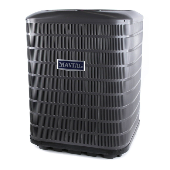
Outdoor Heat Pump
User's Information/Installation Instructions
14 SEER R-410A High Effi ciency Split System
These units have been designed and tested for capacity and effi ciency in accordance with A.R.I.
Standards. Split System Heat Pump units are designed for use with a wide variety of fossil fuel
furnaces, electric furnaces, air handlers, and evaporator coil combinations.
These instructions are primarily intended to assist qualifi ed individuals experienced in the proper
installation of heating and/or air conditioning appliances. Some local codes require licensed instal-
lation/service personnel for this type of equipment. Read all instructions carefully before starting
the installation.
USER'S INFORMATION
Read this owner information to become familiar with the capabilities and use of your appliance.
Keep this with literature on other appliances where you have easy access to it in the future. If a
problem occurs, check the instructions and follow recommendations given. If these suggestions
don't eliminate your problem, call your servicing contractor.
Heat Pump Principle of Operation
WINTER HEATING
1. Outdoor air enters heat pump.
2. Cold, heat-transfer section (outdoor coil)
extracts heat from outdoor air as refrigerant
evaporates from a liquid to a gas.
3. Refrigerant, compressed to a hot gas by
heat pump, carries the heat to the hot heat-
transfer section (indoor coil).
4. Hot, heat-transfer section (indoor coil)
releases the heat to indoor air as refrigerant
condenses from a gas to a liquid.
5. Air handler circulates the heat throughout
the home.
6. Refrigerant returns to outdoor coil and
evaporates once again to absorb more
heat.
IMPORTANT
SUMMER COOLING
1. Indoor air enters the air handler section.
2. Cold, heat-transfer section (indoor coil)
extracts heat from indoor air as refrigerant
evaporates from a liquid to a cold gas.
3. Refrigerant, drawn to heat pump and
compressed to a hot gas by heat pump,
carries the heat outdoors.
4. Hot, heat-transfer section (outdoor coil)
releases the heat as refrigerant condenses
from a gas to a liquid.
5. Heat pump (outdoor fan) discharges the
heat to outside air.
6. Refrigerant returns to indoor coil and
evaporates once again to absorb more
heat.
Advertisement
Table of Contents

Related Manuals for Nordyne CSH4BE


Summary of Contents for Nordyne CSH4BE
- Page 1 Outdoor Heat Pump User’s Information/Installation Instructions 14 SEER R-410A High Effi ciency Split System These units have been designed and tested for capacity and effi ciency in accordance with A.R.I. Standards. Split System Heat Pump units are designed for use with a wide variety of fossil fuel furnaces, electric furnaces, air handlers, and evaporator coil combinations.
- Page 3 OPERATING INSTRUCTIONS and indoor blower will both cycle on and off to maintain the indoor temperature at TO OPERATE YOUR HEAT PUMP the desired heating level. FOR COOLING — NOTE: If the thermostat temperature level is re-adjusted, or the thermostat system 1.
-
Page 4: General Information
TO OPERATE YOUR HEAT PUMP Regularly: FOR AUTOMATIC COOLING AND a. Clean or replace the indoor air fi lter at the start of each heating and cooling season, HEATING — and when an accumulation of dust and dirt is visible on the air fi lter. Inspect the fi lter 1. -
Page 5: Safety Considerations
safety glasses, work gloves, fi re extinguisher, refrigerant for an additional 15 ft. of refrigerant etc.) must be used when performing brazing lines the same size as the valve fi ttings. operations. NOTE: DO NOT USE ANY PORTION OF THE CHARGE FOR PURGING OR LEAK WARNING: TESTING. -
Page 6: Installing The Indoor Unit
liquid line, the fi lter dryer must be replaced with nor transmit noise to the interior of the structure. the one supplied with the unit. The fi lter dryer Refrigerant and electrical line should be routed must be installed in strict accordance with the through suitably waterproofed openings to manufacturer’s installation instructions. -
Page 7: Startup And Checkout
Prior to applying electrical power to the outdoor Minimum Circuit Ampacity — Electrical wiring unit, ensure that the unit has been properly and to the equipment must be compatible and in securely grounded, and that power supply compliance with the minimum circuit ampacity connections have been made at both the facility listed on the outdoor unit data label. -
Page 8: Air Handler
Thermostat G R W 2 C E O Y NOTE: Jumper between W2 and E is required when no OD T-Stat is used. Green Brown Orange For 2-Stage Heater Kits Black Air Handler Heat Pump OD Section Typical Heat Pump with Standard Air Handler... - Page 9 A typical installation with a heat pump thermostat, air handler, and heat pump with an outdoor thermostat. Thermostat G R W 2 C E O Y Green White Black Air Handler Heat Pump OD Section Typical Heat Pump with Outdoor Thermostat and Air Handler...
- Page 10 the thermostat inputs to the unit. Thus, when the ALERT LED (Yellow): communicates an switch opens and then closes, there will be a 5 abnormal system condition through a unique minute short cycling delay before the outdoor fl ash code. The ALERT LED will fl ash a number unit will energize.
- Page 11 Example 2. Moist climate of Seattle, Heating — Lower the thermostat setpoint temperature to the lowest obtainable setting and Washington. A 30 minute setting is set the thermostat function switch to HEATING. recommended. The indoor blower and outdoor unit should stop running.
- Page 12 Status LED Status LED Description Status LED Troubleshooting Information Green “POWER” Module has power Supply voltage is present at module terminals 1. Compressor protector is open Red “TRIP” Thermostat demand signal 2. Outdoor unit power disconnect is open Y is present, but the 3.
- Page 13 Miswired Module Indication Recommended Troubleshooting Action Green LED is not on, Determine if both R and C module terminals are module does not power up connected. Verify voltage is present at module’s R and C terminals. Review 24VAC Power W iring (page 4) for R and C wiring.
-
Page 14: Adjustment Of Refrigerant Charge
Defrost Test Procedure for 624656 Adjustment of Refrigerant Charge: 1. Jumper “T2” to “DFT” at the test terminals. 2. With unit running in heat mode, short the CAUTION: “TEST” terminal to the common terminal near it. This will speed up the board and cause Split system heat pump equipment it to enter defrost mode in 5/10/15 seconds contains liquid and gaseous refrigerant... - Page 15 Refrigerant Charging Charts for Cooling Mode of Operation 14 SEER Split System Cooling Charts 1.5 T on Heat P ump T XV C ooling C harging C hart Remove refrigerant when above curve Add refrigerant when below curve Liquid T emperature (F ) 2 T on Heat P ump T XV C ooling C harging C hart Remove refrigerant when above curve Add refrigerant when below curve...
- Page 16 Refrigerant Charging Charts for Cooling Mode of Operation 14 SEER Split System Cooling Charts 2.5 T on Heat P ump T XV C ooling C harging C hart Remove refrigerant when above curve Add refrigerant when below curve Liquid T emperature (F ) 3 T on Heat P ump T XV C ooling C harging C hart Remove refrigerant when above curve Add refrigerant when below curve...
- Page 17 Refrigerant Charging Charts for Cooling Mode of Operation 14 SEER Split System Cooling Charts 3.5 T on Heat P ump T XV C ooling C harging C hart Remove refrigerant when above curve Add refrigerant when below curve Liquid T emperature (F ) 4 T on Heat P ump T XV C ooling C harging C hart Remove refrigerant when above curve Add refrigerant when below curve...
- Page 18 Refrigerant Charging Charts for Cooling Mode of Operation 14 SEER Split System Cooling Charts 5 T on Heat P ump T XV C ooling C harging C hart Remove refrigerant when above curve Add refrigerant when below curve Liquid T emperature (F )
- Page 24 INSTALLER: PLEASE LEAVE THESE INSTALLATION INSTRUCTIONS WITH THE HOMEOWNER. ¢708695W¤ 708695A 708695A (Replaces 7086950) Specifi cations and illustrations subject to change without notice and without incurring obligations. Printed in U.S.A. (08/08)
Need help?
Do you have a question about the CSH4BE and is the answer not in the manual?
Questions and answers